
Lesson 12. Rigging and Publishing Widgets
Lesson Files
Motion5_Book_Files > Lessons > Lesson_12
Media
Motion5_Book_Files > Media > Audi_FCP_X, Audi_Motion
Time
This lesson takes approximately 90 minutes to complete.
Goals
Rig and publish a checkbox widget for a Final Cut Pro title
Analyze the structure of a Final Cut Transition project
Connect parameters with the Link behavior
Rig and publish a pop-up widget
Create a Final Cut effect project
Rig and publish a slider widget
In the previous lesson, you published both a project and specific project parameters from Motion to make them available for use in Final Cut Pro.
Parameter rigs take the publishing concept to a whole new level. A rig allows you to connect many parameters into a single control, called a widget. Instead of publishing several individual parameters, you publish a single widget that controls the parameters in ways that you specify, making it faster and easier to adjust an effect in Final Cut Pro.
Motion provides three types of widgets, and in this lesson, you’ll work with all of them—checkboxes, pop-up menus, and sliders—to publish simple, powerful controls for Final Cut Pro X. You’ll do this for three types of projects: a title, a transition, and an effect.

Rigging a Checkbox Widget
You finished the previous lesson by publishing an animated title and several parameters. Now, you’ll give Final Cut Pro editors even more flexibility by publishing a rig to control the direction of that title animation.
1. Navigate to Motion5_Book_Files > Lessons > Lesson_12 > Audi Lower Third Start, and open the Audi Lower Third.moti project.
This file is a completed version of the project you made in the previous lesson. Before you work with it, however, you need to publish it to Final Cut Pro X.
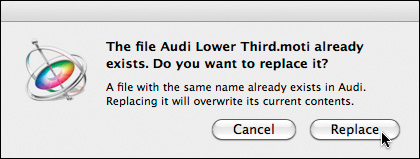
2. Choose File > Save As. Name the template Audi Lower Third, and save it to the Audi category. (Create the category, if necessary.) Do not include unused media, click Publish, and if necessary, click Replace.
This project will replace the one you created in the previous lesson unless you give it a different name.
3. Play the project to reacquaint yourself with the animation.
The arrows fly onto the screen from the left to the right, revealing the asphalt texture. The text then animates on in the same direction. But what if you wanted to reverse this animation?
In this exercise you’ll enable your Final Cut Pro editor to change the direction of the animation so the arrows and the text move from right to left.
While you could publish all the individual parameters required to make these changes, a rig enables you to connect these parameters to a single control, called a widget, that you can publish to Final Cut Pro. But before you can add a widget to your project, you need to create a rig to contain it.
4. Stop playback. Choose Object > New Rig.
A new layer named Rig appears in the Layers list. A rig is a container for widgets much like a group is a container for layers.
5. Press F4 to open the Rig Inspector.
The Rig Inspector contains three buttons representing the three types of widgets that you can add to a rig: Slider, Pop-up, and Checkbox.

6. Click the Checkbox button.

The checkbox widget appears under the Rig layer in the Layers list. Let’s change its name to something that describes its function: reversing the animation’s direction when the checkbox is selected.
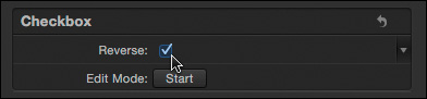
7. In the Layers list, double-click the Checkbox layer name to select the text, type Reverse, and press Return.
With the widget selected in the Layers list, the fourth pane of the Inspector becomes the Widget Inspector. In addition to containing your renamed Reverse checkbox, it also contains an Edit Mode option that has a Start button.

8. Click the Reverse checkbox to select it.
A checkbox is the simplest type of widget, because it has only two states: selected or deselected. Each of these states is called a snapshot, and each snapshot contains parameter values you select. When you change the snapshot by selecting and deselecting the checkbox, those parameter values change. That may seem confusing now, but it will be more understandable after you “rig” the widget.
In order for the checkbox widget to affect a parameter value, the parameter must be added to the widget. This process is called rigging the parameter to the widget. You can rig parameters to a widget manually or automatically. Let’s rig parameters automatically using a special mode called Rig Edit Mode.
9. With the Reverse checkbox selected, in the Widget Inspector, click the Edit Mode Start button.

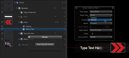
A window appears to remind you that you are in Rig Edit Mode. Any parameter changes you make will now be stored as part of the checkbox widget’s “checked” state. So you’ll now make all the changes necessary to reverse the animation.
10. In the Layers list, open the group named Group, the Elements group, and the Arrow layer. Select the Motion Path behavior, and in the HUD or the Behaviors Inspector, change the Direction parameter from Forward to Reverse. Play the project.
The arrow now moves to the left, but it’s still pointing to the right.
11. Press F1 to go to the Properties Inspector, and change the Rotation parameter from 180 degrees to 0.
That’s better, but the mask revealing the asphalt graphic also needs to point and animate in the opposite direction.
12. In the Layers list, open the Mask layer. Select the Motion Path copy behavior, and in the HUD or the Behaviors Inspector, set its Direction parameter to Reverse.

The mask now animates in the correct direction, but it isn’t properly revealing the graphic.
13. Stop playback and click the Mask layer’s activation checkbox so that you can see the layer in the Canvas. In the Properties Inspector, change its Rotation Z value to 180 degrees, and then in the Canvas, with the playhead at or near frame 23, drag the mask to the right to line it up with the first red chevron shape. Deselect the activation checkbox to hide the Mask layer and scrub through the project.
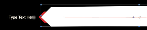
The mask reveals the asphalt texture as the arrows pass over. Now let’s tackle the text.
14. Open the Type Text Here layer, select the Blur In behavior, and in the HUD or the Behaviors Inspector, change the Direction parameter to Backwards.
15. Move the playhead to a frame where the red chevrons have passed over the last letter of the text, at about frame 23. Select the Type Text Here layer, and press Shift-[ (left bracket) to move the In point of the layer and behavior to the playhead. Play the project.
Now the text animates from right to left, matching the arrow animation; and it doesn’t start to appear until after the chevrons have moved past it.

You’ve changed everything needed to reverse the entire animation.
16. In the floating window, click the Stop Rig Edit Mode button, and save your work.
Modifying, Testing, and Publishing a Widget
After you stop Rig Edit Mode, it’s time to inspect the widget, test it, and publish it to Final Cut Pro.
1. In the Layers list, close Group, select the Reverse widget, and go to the Widget Inspector.
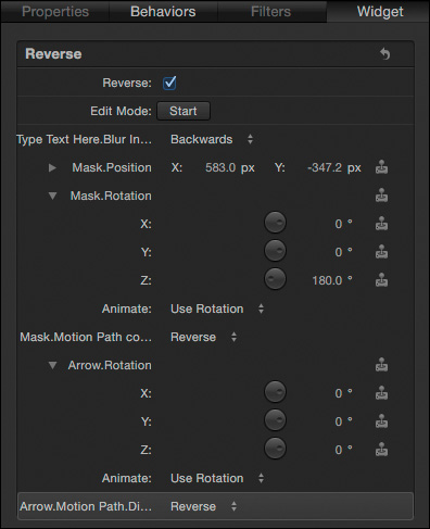
Every parameter you adjusted while in Rig Edit Mode now appears under the Reverse checkbox widget. Next to the Animation menu of each parameter, a joystick icon indicates that the parameter is rigged. What this joystick means is that the parameter’s value is tied to a specific snapshot of the widget. Because the checkbox was selected while in Rig Edit Mode, the values you set are tied to the “checked” snapshot for the widget. You can see the values change when you change the snapshot.
2. Deselect the Reverse checkbox.
Notice that the values of most of the parameters change back to the original values that existed before you changed them in Rig Edit Mode.
The reason all the values don’t necessarily change is that when parameters are added to a snapshot in Rig Edit Mode, all the channels of the parameter are added. For example, even if you just change the Z-rotation of a layer, Motion adds the X, Y, and Z rotation values to the widget.
3. Start playback and click the checkbox a few times.
When the checkbox is deselected, the animation plays left to right as it did when you first opened it. When it is selected, the animation plays right to left. This one simple checkbox widget controls the values of all the parameters rigged to it.
Now that you’ve rigged and tested the widget, the next step is to publish it.
When in Rig Edit Mode, you also moved the start of the Type Text Here layer to a new frame. But when you toggle the checkbox, the text layer does not return to its original position. This is because some project changes don’t have an associated parameter you can rig to a widget. These changes include trimming and moving layers, and selecting or deselecting layer activation checkboxes. In this case, the animation still looks good in both directions with the text starting a little later, so you can leave it as it is.
4. Make sure the checkbox is deselected. This snapshot will be the default. Click the Animation menu for the Reverse widget, and choose Publish.
The widget now appears as a published parameter.

5. In the Layers list, select the Project layer.
6. Press F4 to open the Project Inspector, and if necessary, click the Publishing pane.
The Reverse checkbox appears below the other parameters you published in the last lesson. Let’s see how this widget works in Final Cut Pro.
You can also test any published parameters here in the Project Inspector by changing their values. When you are satisfied, leave each parameter with the default value you want to publish to Final Cut Pro.

7. Save your work, close the project, and switch to Final Cut Pro, or open it, if necessary.
If you did not complete Lesson 11, you’ll need to return to that lesson and complete the seven steps in the “Setting Up the Final Cut Pro Project” section. You’ll then need to click in the middle of the Paul_006 clip to select it, and press the Up Arrow to move the playhead to the first visible frame of the clip, which appears in the Viewer. You can then proceed to step 9.
8. Select the title in the Timeline.
9. In the Titles Browser, select the Audi category, and double-click the Audi Lower Third thumbnail to replace the Timeline version.
10. Select the title in the Timeline once more, and go to the Title Inspector. (If necessary, press Command-4 to open the Inspector, and then click the Title button.) Select the Reverse checkbox and play the title.
The animation plays in the opposite direction with the checkbox selected.

Congratulations, you’ve built and published your very first parameter rig! Next, you’ll explore the pop-up widget using a completed transition project.
Deconstructing a Transition Project
The checkbox widget toggles between two snapshots, but sometimes you need more than just two options. The pop-up widget lets you set up as many snapshots as you like and display them in a list. In this exercise, you’ll use a pop-up widget to rig three shape options for a transition that you will then apply to the Audi project in Final Cut Pro. You’ll start with a completed Final Cut transition so that you can focus on the rigging process. Let’s see how the transition is constructed.
1. Navigate to Motion5_Book_Files > Lessons > Lesson_12 > Audi Chevron Wipe Start, and double-click the Audi Chevron Wipe.motr project to open it in Motion.
2. Choose File > Save As, and in the window that appears, name the template Audi Chevron Wipe. Create the Audi category, deselect “Include unused media,” select Save Preview Movie, and click Publish.

Motion saves the project, and after a few seconds, generates a preview movie. Because the design of this project is complete, you can immediately publish it to Final Cut Pro along with a preview movie. Now, while you rig the project, you can save as you go by pressing Command-S without the need to specify the publish settings.
3. In the Layers list, open the Transition Placeholder group. Press Shift-Z to fit the Canvas to the window, and play the project.
A Final Cut title project contains one placeholder layer, whereas a Final Cut transition contains two placeholder layers: one for each side of the edit point. The green layer, Transition A, represents the outgoing video clip; the red layer, Transition B, represents the incoming video clip.

4. Stop playback. In the transport controls at the bottom of the Canvas, click the Go To Start and Go To End buttons to move the playhead to the first and last frames of the project.
A clean view of Transition A fills the first frame, and a clean view of Transition B fills the last frame. Transitions always start and end with an unaltered view of the outgoing and incoming video. Between these points, graphics fly across in both directions as Transition B wipes onto the screen.
In the Layers list, the small arrow on the icon on each of the transition placeholders indicates that you can replace the default graphic with video or graphics, much like a drop zone, to see how the transition will look in Final Cut Pro.
5. In the File Browser, navigate to Movies > Final Cut Events > Audi Promo > Original Media. With the playhead at the start of the project, drag the first clip, ALXA_004.mov, over the Canvas, wait for the yellow outline around the Transition A placeholder to appear, and release the mouse button. The video clip replaces the green graphic.
6. Move the playhead to the end of the project, and from the File Browser, drag the ALXA_074.mov clip to the Canvas to replace the Transition B placeholder. Play the project. Now you can see what the transition might look like in the context of the Audi Promo project.

Your goal with this project is to rig it so that an editor working with Final Cut Pro can choose different graphics to wipe across the screen. But before you can build the rig, you need to understand how the project is constructed.
7. Stop playback. Switch the Timing Display to frames, if necessary, and move the playhead to about frame 28 so you can see both clips. Close the Transition Placeholder group, and open the Chevrons group.

The Chevrons group contains four groups of its own. The top Master Chevron group’s activation checkbox is deselected, so that group isn’t visible in the Canvas. Even though its content is not visible, the Master Chevron group is being used to control the content in all the other groups. Let’s see how.
8. Open each of the four groups inside the Chevrons group.
To see all the layers, you may need to resize their heights by dragging up between any two layers.

The Master Chevron group contains three graphics layers. You can tell from the preview icon that only the top layer, Double Arrows, is visible. The other layers are activated, but their Opacity parameters are set to 0.
You may wonder why you can see the Double Arrows layer in the Canvas, when the group that contains it, Master Chevron, is deactivated. It’s because you are actually seeing a clone of that group.
The three groups below the Master Chevron group contain clone layers of the Master Chevron group. The silhouette badge on each layer icon indicates that the layers are clones.
9. In the Chevrons huge wipe group, select the bottom layer, Chevron huge 1, and if necessary, press F4 to open the Layer Inspector.

This layer is a clone of the Master Chevron group, and therefore displays the content of that group (even though the source group is deactivated). If you change which layer is visible in the source group, the content in the Canvas updates.
10. In the Master Chevron group, select the Double Arrows layer. In the HUD, change its Opacity to 0 percent. Then select the Single Arrow layer below it, and in the HUD, increase its Opacity to 100 percent.

In the Canvas, all the double arrows are replaced with single arrows. Because all the animated graphics in this project are cloned from a single group, you can change all the graphics in the project simply by “turning on” the appropriate layer in the clone source, the Master Chevron group. Thanks to this efficient project design, it will be easy to build a parameter rig to control all the graphics that animate across the screen during the transition.
Similarly, all shape layers in the project (indicated in the Layers list by orange shape icons) are clones of the Arrow Background shape in the Master Chevron group. These shape layers create the blurred red background behind the graphics, and they don’t need to change when the graphics change.
11. Close all the groups inside the Chevrons group except for the Master Chevrons group. By doing so, you can focus your attention on the group that controls the look of the project.
Rigging a Pop-Up Widget
This project contains three different graphics options, so for this widget you need a way to choose three different “states,” or snapshots. The pop-up widget contains a menu to which you can add as many snapshots as you like. You create the snapshots, name them, rig parameters to them, and set the appropriate parameter values for each snapshot. First, however, you must create a rig to contain the widget.
1. Choose Object > New Rig, or press Command-Control-R.
2. From the Rig Inspector (press F4, if necessary), click the Pop-up widget button.

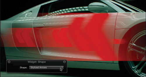
3. In the Layers list, rename the Pop-up widget layer to Shape to make it clear that this widget will let you choose the shape of the graphics for the project.
4. In the Widget Inspector, click what is now the Shape pop-up menu.

By default, this menu has three choices: Snapshot 1, 2, and 3. You can change the name and number of snapshots in the menu.
5. With Snapshot 1 selected, click the Rename button, and type Double Arrows. Press Return. The rigging process will be easier if you name the snapshots in the same order as the layers in the Layers list.
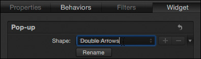
6. Select and rename Snapshot 2 to Single Arrow, and rename Snapshot 3 to Stylized Arrows. Refer to the Layers list to match the order and naming of the snapshots to the layers.

You need only three snapshots here, but let’s see how you would add another.
7. Next to the Shape pop-up menu, click the + (plus sign) button.
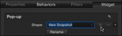
A new snapshot appears, named appropriately enough, New Snapshot.
8. Press Return to accept the snapshot name, and then click the – (minus sign) button to delete the snapshot. The three snapshots are all you need in this exercise.
Now that you’ve created your snapshots, you can turn your attention to rigging parameters to the widget. In the previous exercise, you used Rig Edit Mode to automatically add parameters to the widget for multiple layers and effects as you changed their values. In this exercise, you want to rig only a few parameters (the Opacity parameters for the graphics layers in the Master Chevron group). Because you’re rigging only three layers, you can easily rig the parameters and set their states manually.
9. In the Layers list, select the Double Arrows layer. Press F1 to open the Properties Inspector. Locate the Opacity parameter, and from its Animation menu, choose Add To Rig > Rig > Add To Shape.
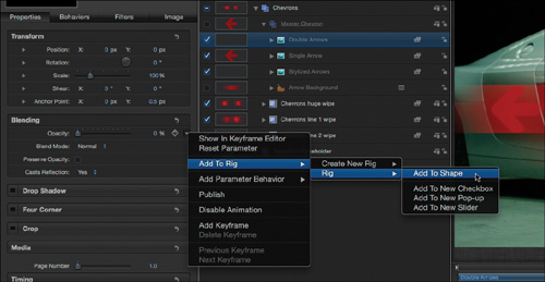
The submenu lists available rigs and widgets. Since you didn’t rename the rig, it appears as Rig; but your widget appears in the menu with its new name, Shape.
You can use the Add To Rig command even if you haven’t yet created any widgets—or even if you don’t yet have a rig in your project! Choose Add To Rig > Create New Rig > Add To New Checkbox, Pop-up, or Slider. This is an efficient way to create a rig, add a widget, and rig a parameter to the widget in one step.
A small joystick icon next to the Animation menu for the Opacity parameter indicates that the parameter is now rigged.

10. Repeat the same process to rig the Opacity parameter for the Single Arrow and Stylized Arrows layers. Then, select the Shape widget in the Layers list.

In the Widget Inspector, the Opacity parameters for each of the three layers now appear, along with their current values. Notice, however, that the stacking order is reversed compared to the order in the Layers list. This is because each time you rig a parameter, it is added to the top of the list.
When rigging more than a few parameters, it can be helpful to first add the lowest one in the Layers list and work your way up to match the order of the Layers list.
You cannot drag rigged parameters in a widget to change their order the way you can drag published parameters to reorder them in the Project Inspector. Instead, you need to use the Animation menu to remove parameters from the widget, and then add them again in the order you desire.
With all the necessary parameters rigged, you now can set the values of these parameters for each snapshot.
11. From the Shape pop-up menu, choose Double Arrows.
12. Set the Double Arrows Opacity value to 100, and the value of the other two parameters to 0.

13. Choose Stylized Arrows from the pop-up menu. Set the Stylized Arrows Opacity value to 100 and the others to 0.
You can skip the middle snapshot, Single Arrow, because the opacity values are already set correctly for that snapshot.
14. In the HUD, select each of the snapshot states and watch as the graphics update in the Canvas.
The final step is to publish the widget to make it available in Final Cut Pro.
15. From the Animation menu for the Shape pop-up menu widget, choose Publish. In the Layers list, select the Project, and in the Publishing pane of the Project Inspector confirm that the widget is published.

You can now choose the shape of the graphic for this transition in Final Cut Pro. Before testing it, however, let’s also give the Final Cut Pro editor the ability to change the color of the graphics.
Using the Link Parameter Behavior
The color of the graphics in this project comes from filters applied to the three layers in the Master Chevron group. While you could directly publish the color swatch for each of the three filters, every time the Final Cut Pro editor changed the Shape snapshot, she would also need to change the corresponding color for that graphic.
You can be more efficient by connecting the color of all the shape graphics to a single “master” layer using the powerful Link parameter behavior. With this method, the Final Cut Editor can quickly customize the colors of the transition elements using a single color swatch in order to apply that new color to all three Shape options.
1. In the Layers list, in the Master Chevron group, open each of the three arrow layers to reveal the Tint filters.

You’ll link the tint color of the lower two layers to the top layer. To make it clear that the top Tint filter will control the other two filters, you can rename it.
In this simple project, you could apply a single Tint filter to the Master Chevron group to tint all the shape options. However, in many projects it is necessary to use filters on multiple layers, and the Link behavior is a great way have them work in unison.
2. In the Double Arrows layer, double-click the Tint filter, and rename it to Tint Master.
3. In the Single Arrow layer, select the Tint filter, and press F3 to open the Filters Inspector.
4. Click the Animation menu for the Color parameter (or right-click the word Color), and from the pop-up menu, choose Add Parameter Behavior > Link.

The Link behavior appears underneath the layer in the Layers list. It is disabled because it has no source. In the Behaviors Inspector (which appeared automatically after you selected the Link behavior), you’ll find a well for adding a source object. You can’t add filters directly to the well, so you’ll add the layer to which the filter is applied.
5. Drag the Double Arrows layer from the Layers list to the Source Object well in the Behaviors Inspector.
Next, you’ll choose the source object parameter to which you want to link the color of the Tint filter.

6. In the Behaviors Inspector, from the Compatible Parameters pop-up menu, choose Filters > Tint Master > Color > All.

The color of the Single Arrow layer is now linked to the color of the Double Arrows layer. Let’s link the Stylized Arrows layer color in the same manner, this time using both the Filters Inspector and the HUD.
7. Under the Stylized Arrows layer, select the Tint filter. Press F3 to open the Filters Inspector. Control-click the Color parameter, and choose Add Parameter Behavior > Link.
8. Drag the Double Arrows layer from the Layers list to the well in the HUD. Then from the Compatible Parameters menu, choose Filters > Tint Master > Color > All.

Finally, you must link the color of the blurred Arrow Background shape layer.
9. In the Layers list, select the Arrow Background layer. In the Shape Inspector, add the Link Parameter behavior to the Fill Color parameter.

10. Drag the Double Arrows layer to the well in the Behaviors Inspector or the HUD, and from the Compatible Parameters pop-up menu, set the Source Parameter to the Tint Master filter color.
Let’s test all the linked layers.
11. In the Layers list, select the Tint Master filter. In the HUD, change the color of the color swatch. The colors of all the graphics in the Canvas change because they are cloned from the Master Chevron group.
12. In the Layers list, select the Shape widget, and in the HUD, choose each of the snapshots. Every snapshot is the same new color because they are all linked to the Double Arrows snapshot.

13. Press Command-Z a few times to undo the color change. Let’s keep red as the default color. To finish, you just need to publish the Tint Master color swatch.
14. Select the Tint Master filter, and in the Filters Inspector, from the Animation menu for the Color parameter, choose Publish.
15. In the Layers list, select the Project, and in the Publishing pane of the Project Inspector, confirm that the color swatch is published. Test the published parameters, and then undo any changes to restore the default values.

You need to do one more thing to make this transition play correctly in Final Cut Pro.
16. With the project still selected in the Layers list, open the Properties Inspector.
This project’s duration is two seconds. Final Cut Pro’s default transition duration is one second, which is too fast for this project.
17. Select the Override FCP Duration checkbox. Now the transition will play for the full Motion project duration, two seconds, when it is applied in Final Cut Pro.

18. Close all the groups in the Layers list, and press Command-S to save the project. Deselect the Include Unused Media checkbox, and click Don’t Copy.

Because you replaced the placeholder images with video clips after the previous save, you are now presented with some options. If you choose Copy, the video clips and the project file are copied to Home > Movies > Motion Templates > Transitions > Audi. The content you added will also appear in the static thumbnail in Final Cut Pro. For templates designed to be used in many types of projects, it’s often a good idea to clear the placeholder content before closing the project by selecting each placeholder and clicking the Clear button in the Image Inspector. You don’t need to clear the placeholder content for this exercise.
19. Switch to Final Cut Pro, select the Transitions Browser, select the Audi category, and skim the Audi Chevron Wipe thumbnail.
If you do not see the Audi category in the Transitions Browser, quit and relaunch Final Cut Pro X.

The thumbnail displays the video clips, but as you skim, the clips are replaced with the default lake and trees images. This is because you did not copy the placeholder media.
20. Drag the transition onto an edit point between any two clips in the Timeline, select the transition, and adjust the published parameters in the Inspector.

Excellent work! You explored a Final Cut transition project, rigged it with the pop-up widget to publish multiple shape options, and applied the Link Parameter behavior to enable changing the color of all the shape options in Final Cut Pro with a single control. For the final exercise in this lesson, you’ll create a Final Cut effect project and rig it with the third and final kind of widget.
Creating a Final Cut Effect
To work with the third type of widget, the slider, you’ll build a simple Final Cut effect project using clones and filters, and then rig the effect so a single slider can control its overall intensity in Final Cut Pro X. Finally, you’ll publish a few additional parameters to provide even more design flexibility.
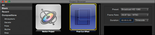
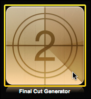
1. Switch back to Motion, close any open projects, and press Command-N to open a new project. Click the Final Cut Effect icon, set the Preset to Broadcast HD 1080, the Frame Rate to 29.97, and the Duration to 5;00. Click Open.
2. Press Shift-Z to fit the Canvas to the window.
Much like a Final Cut title or transition, a Final Cut effect project contains a placeholder. In this case, it’s called the Effect Source, and it represents the video clip to which you will apply the effect in Final Cut Pro. When designing an effect, it’s very helpful to replace the placeholder default graphic with an image or video clip.
Your goal is to make a stylized look for the slow-motion car clips, so you’ll add one of those clips to the placeholder.
3. In the File Browser, navigate to Movies > Final Cut Events > Audi Promo > Original Media. Drag the PHNTM_001.mov clip to the Canvas, wait for the yellow outline to appear around the Effect Source placeholder, and release the mouse button. The video clip replaces the graphic.

The video looks very dull and flat compared to the same clip in the Final Cut Pro X Timeline. That’s because the clip in Final Cut Pro has been color corrected, and here we are looking at the original, unaltered clip. Let’s create an effect that can be used as an alternative to that color correction.
One way to punch up a flat image with little contrast is to copy it on top of itself and combine the two layers with a blend mode. Although an Effect Source placeholder cannot be duplicated like ordinary layers, it can be cloned.
4. With the Effect Source layer selected, choose Object > Make Clone Layer, or press K. Then, move the Clone Layer below the Effect Source layer.
5. Reselect the Effect Source layer, and in the HUD, change its Blend Mode to Overlay.
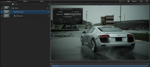
The image immediately looks better because the blend mode gives it darker blacks and brighter highlights. You’ll take this look further by color correcting the image using a few filters.
You may wonder why we moved the clone layer below the original effect source. When a filter is applied to a source layer that has been cloned, the filter will also be applied, or “pass through,” to the clone. However, filters (and other effects) applied to clones directly do not affect the source. With the clone layer placed beneath the original, you can change its look independently of the original layer. Let’s try that now.
6. Select the Clone Layer, and in the toolbar, click the Filters pop-up menu and choose Color Correction > Gradient Colorize.
The Gradient Colorize filter maps an editable gradient to the tones of the image. The default gradient creates more contrast, but also makes the image a little too dark.
7. Click the Filters button again, and choose Color Correction > Gamma. In the HUD, set the Gamma parameter to about 1.52.

The gamma filter lets you adjust the midpoint of the brightness values without affecting the darkest and lightest areas.
Because the Effect Source layer isn’t affected by the filters, you can compare your results so far to the original clip by simply turning off the clone.
8. In the Layers list, toggle the activation checkbox for Clone Layer to switch between the original clip and the current design.
You can see how a blend mode and a few filters have given the clip a much punchier look. Let’s take the technique a step further by adding one more filter to the group containing the layers so that the filter affects them both.
9. In the Layers list, select Group. In the toolbar, click the Filters pop-up menu, and choose Stylize > Bad Film. Play the project.
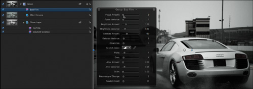
The Bad Film filter adds dirt, hair, and scratches to the clip; makes it shake and flicker; and even shifts the focus. You can adjust several parameters to change the look of the filter. Feel free to play with their settings.
With the basic design of the effect completed, you can now decide how to make the effect adjustable in Final Cut Pro. First, however, save your work.
10. Press Command-S to save the project.
11. Name the template Gradient Contrast-Bad Film, and create a new Audi category. Deselect Include Unused Media, leave Save Preview Movie deselected, and click Publish.

Because the placeholder contains a video clip, it is included when you create a preview movie. You can choose to create the preview movie later, after clearing the placeholder, to get a generic preview.
Also because the placeholder does contain a video clip, a copy of the clip is saved with the effect, which can waste disk space. You can remove the clip by navigating to Movies > Motion Templates > Effects > Audi > Gradient Contrast-Bad Film > Media and moving it to the Trash.
Rigging the Slider Widget
At this point, your new effect can be applied in Final Cut Pro, but it can’t be adjusted without returning to Motion. The great thing about rigging and publishing is that you can choose what elements of a Motion project to “expose” to a Final Cut Pro editor so he can change the look of the effect directly in Final Cut. There are a lot of options! Often you’ll want to find the balance between giving the editor enough control to modify an effect to his liking, while not overwhelming him with dozens of published parameters. The slider widget is a great tool for controlling multiple parameters at once, over a range of values you specify.
For this project you’ve just created, you’ll add and publish a slider to control the overall impact of combined effects—from no impact at all, to the fully stylized look you have now. You’ll also give the Final Cut Pro editor the ability to change the gradient used by the Gradient Colorize filter by publishing the Gradient editor. Finally, because the Bad Film filter is such a dramatic effect, you’ll publish a separate control so the Final Cut Pro editor can add it independently of the color and contrast adjustments.
1. In the Layers list, turn off the Bad Film filter by deselecting its activation checkbox.
Now you can focus on the impact of the other filters and the blend mode. Let’s add the slider widget.
2. Choose Object > New Rig, or press Command-Control-R.
3. Press F4 to view the Rig Inspector, and click the Slider button.
The slider widget appears below Rig in the Layers list. You want it to control the overall intensity of the project, so let’s rename it right away.
4. In the Layers list, rename the slider widget to Intensity.
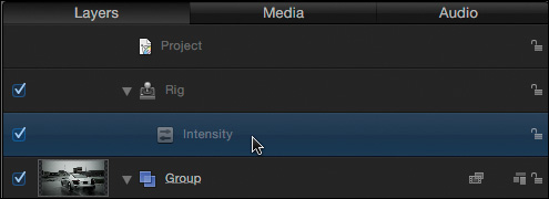
In the Widget Inspector, the slider appears with the new name, Intensity. Underneath each end of the slider you’ll see dots that represent snapshots. The left dot is blue because it is the active snapshot. Before working with the slider and the snapshots, you’ll rig the parameters to the widget.

Your goal is to choose parameters to add to the rig that change the intensity of the effect. Often, multiple parameters will have a similar impact. By using Rig Edit Mode, any parameter changes you make are automatically added to the widget. Let’s start with the Gamma filter.
5. In the Widget Inspector, click the Start button to enter Rig Edit mode.
6. Select the Gamma filter, and press F3 to reveal the Filters Inspector.
In addition to filter-specific parameters, most filters have a Mix parameter that modulates the impact of the filter.
7. Drag the Mix slider all the way to the left.
8. Drag the Gamma slider left and right, and then leave it at a different setting from the starting value.
The Gamma parameter makes the image brighter or darker. When you change each parameter in Rig Edit Mode, you add both parameters to the widget.
If you change a parameter and then restore its original value, the parameter is not added to the widget.
Below the Gamma filter controls in the Filters Inspector, you’ll find the controls for the Gradient Colorize filter. This filter has several parameters, but only the Mix parameter will eliminate its impact.
9. In the Filters Inspector, set the Mix slider for the Gradient Colorize filter to 0.
10. Select the Effect Source layer, and in the HUD, drag the Opacity slider to 0.
The clip now looks as it did originally.
11. In the floating window, click the Stop Rig Edit Mode button.
12. In the Layers list, select the Intensity widget, and return to the Widget Inspector.
The four parameters you adjusted in Rig Edit Mode appear below the slider.

Since the active snapshot is the blue dot at the left of the scale, you need to set the values for all the parameters to make the clip look like the unaffected original.
13. Set the values for all the parameters that you added to the widget to 0 except the Clone Layer.Gamma.Gamma parameter. Set that parameter to a value of 1 so that it has no impact.
With the Intensity slider positioned all the way left, the clip isn’t affected at all. Now, you’ll set values for all these parameters when the slider widget is at its maximum value.
14. Click the dot below the right side of the slider widget to select that snapshot.
The parameter values automatically return to their values before you started Rig Edit Mode.
15. If necessary, set all the parameter values to 100% except the Clone Layer.Gamma.Gamma parameter. Set its value back to 1.52. The filters and blend mode now all affect the image.

16. Drag the Intensity slider between the two snapshots. As you drag, all the rigged parameters values change simultaneously to reduce the overall effect.
17. Leave the Intensity slider at about the middle position and save your work.
The single Intensity slider now controls four separate parameters from two filters and an image layer. Nice work. The final step is to publish the widget and test it—but let’s publish a few other parameters as well to give the Final Cut Editor more flexibility.
You can add intermediate snapshots to the slider widget by clicking anywhere underneath the slider. You can move the snapshots left or right, and set new parameters values for each snapshot. In this way, you can control how quickly parameter values change as you drag the slider from one end to the other.
Publishing Widgets and Parameters
Let’s publish our new Intensity widget, the Gradient editor for the Gradient Colorize filter, and the Bad Film filter; then you’ll modify the published parameters and test them in Final Cut Pro.
1. In the Widget Inspector, from the Animation menu for the Intensity widget, choose Publish.
2. In the Layers list, select the Gradient Colorize filter, and if necessary, press F3 to open the Filters Inspector.
The default gradient is white on the left and changes to black on the right. But the gradient colors can be edited to create a completely different look. Let’s publish the entire gradient to Final Cut Pro. Although the Gradient parameter doesn’t have an Animation menu, you can still publish it.
3. Control-click the word Gradient, and from the shortcut menu, choose Publish.

Finally, let’s return to the Bad Film filter. Rather than publish individual parameters, you can publish the filter’s activation checkbox.
4. Select the Bad Film filter, and in the Filters Inspector, Control-click the words Bad Film, and from the shortcut menu, choose Publish.

Now, let’s look at what we have.
5. In the Layers list, select the Project, and go to the Publishing pane of the Project Inspector.

The Intensity slider widget, the Gradient editor, and the Bad Film activation checkbox are all here.
6. Test each of the published parameters by changing their values, and then return them to their default values.
Although the Gradient editor includes a pop-up menu of gradient presets in the list of Published Parameters, that menu will not appear in Final Cut Pro. Instead, you’ll edit the gradient directly.
In terms of workflow in Final Cut Pro, it may make the most sense to first edit the gradient, and then adjust the overall intensity of the effect. Then, you can add the Bad Film effect if you desire. Therefore, let’s change the order of the published parameters.
7. Drag the Gradient editor above the Intensity slider.

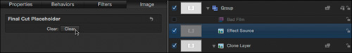
As a final step, let’s clear the Effect Source.
8. Select the Effect Source layer, and in the Image Inspector, click the Clear button. The Effect Source and Clone Layer return to the default graphic.
Time to check out the results in Final Cut Pro.
9. Save the project and switch to Final Cut Pro.
10. Open the Effects Browser, select the Audi category, and drag the Gradient Contrast-Bad Film effect onto one of the PHNTM clips in the Timeline.
If necessary, quit and relaunch Final Cut Pro for the new effect to appear in the Effects Browser.

11. Select the clip with the applied effect, and in the Inspector, deselect the Correction 1 color correction.

By turning off the color correction, only your new effect affects the video clip.
12. Open the Gradient Editor, change the color of the color tags, add new tags, and adjust their locations. Drag the Intensity slider to create a customized look.

13. Select the Bad Film checkbox to activate it, and play the clip.
Because Final Cut Pro effects are applied directly to clips, they always expand or contract to fit the clip duration. Because the Bad Film effect is animated, it speeds up or slows down based on the clip length. You can set the animation speed to a fixed rate using a Loop End marker in Motion. See “Working with Markers in Templates” under the Motion 5 Help menu for more information.
14. Try turning on the Correction 1 color correction, and then adjusting your effect parameters for a still different look.

Congratulations! In this lesson, you covered a lot of ground working with titles, transitions, and effects. You learned how to rig, modify, and publish checkbox, pop-up, and slider widgets manually and in Rig Edit Mode. And along the way you learned a few tricks for building motion graphics projects in Motion.

Lesson Review
1. What is the relationship between a rig and a widget?
2. Describe two ways to add a parameter to a widget.
3. What is the simplest type of widget and why?
4. How do you know if a parameter has been rigged?
5. What does the green placeholder layer in a Final Cut transition project represent?
6. When you finish rigging a widget, what do you have to do to make it available in Final Cut Pro X?
7. In Motion, how can you display a list of all published parameters?
8. You want to rig a transition so that you can choose from five color themes in Final Cut Pro. What type of widget should you choose?
9. You want to rig a generator so that the Final Cut Pro editor can rotate all the graphics at once to point in any direction. What type of widget should you use?
Answers
1. A rig is a container for widgets, much like a group is a container for layers. Before you can add a widget to a Motion project, you must first add a rig to contain the widget.
2. You can add a parameter to a widget manually by choosing Add to Rig > (Rig name) > Add to (Widget name), or automatically by clicking Start to enter Rig Edit Mode and changing the value of the parameter.
3. A checkbox is the simplest type of widget because it has only two states: selected or deselected. Each state is called a snapshot and contains parameter values that you select.
4. Next to the Animation menu of a parameter, a joystick icon indicates that the parameter is rigged.
5. A Final Cut transition contains a placeholder layer for each side of the edit point. The green layer, Transition A, represents the outgoing video clip; the red layer, Transition B, represents the incoming video clip.
6. You need to publish the widget to use it in Final Cut Pro X.
7. In the Layers list, select the project, and then in the Project Inspector, select the Publishing pane.
8. The pop-up widget allows you to set as many discrete snapshots as you’d like to place in a menu.
9. The slider widget lets you set up snapshots for maximum and minimum values and then choose any value between them by dragging the slider.