3. Working with Objects
Introduction
Adobe Illustrator is an application that gives you great control over vector graphics, which include vector shapes and vector objects. Vector graphics are created using mathematical shapes, not pixels, and that’s why vector shapes are considered resolution-independent. When you draw a vector object, you create one or more lines called a path. A path is made up of one or more curved or straight line segments. The start and end points for a line segment is known as an anchor point, which you can drag to change and move.
Illustrator provides drawing tools on the Tools panel that you can use to create a variety of shapes, including rectangles, rounded rectangles, ellipses, polygons, stars, flares, lines, arcs, spirals, rectangle grids, and polar (circular) grids. After you draw an object, you can use Illustrator selection tools to modify it. The two main selection tools are the Selection tool and the Direct Selection tool. The Selection tool allows you to select entire objects, while the Direct Selection tool allows you to select paths and segments. In addition to these tools, you can also use the Select menu. The Select menu provides a variety of powerful selection commands for you to use in a document or artboard. For example, you can select objects whose attributes (including Appearance, Blending Modes, Fill & Stroke, Opacity, and Stroke Color) are similar to the current or last selection.
After you select one or more objects, you can move, align, group, and transform them. The transformation tools allow you to rotate, scale (resize), reflect (mirror image), or shear (slant) an object.
Understanding Vector and Raster Graphics
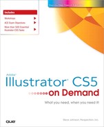
Illustrator is an application that gives you great control over vector graphics, which include vector shapes and vector objects. Vector graphics are created using mathematical shapes, not pixels, and that’s why vector shapes are considered resolution-independent. For example, if you enlarge a vector image to 100 times its original size, Illustrator merely changes the mathematical formulas to reflect the new size, and since vector shapes are constructed of mathematical data instead of pixels, file sizes are extremely small.
Raster graphics, such as bitmaps and photographs, are images creating using individual pixels that identify one piece of color information. The reason raster images are considered resolution-dependent is that once the image is created or scanned, any enlargement of the image forces Illustrator to enlarge and average the existing color information in the document. This process, called interpolation, is what causes enlarged raster images to become blurred, or pixelated.

Understanding Paths
When you draw an object, you create one or more lines called a path. A path is made up of one or more curved or straight lines, known as segments. The start and end points for a segment is called an anchor point. An anchor point is a bending point to modify the line segment. A path can be open or closed. An open path has open-ended endpoints, such as a line, while a closed path has connected endpoints, such as a circle. Paths can have two types of anchor points: smooth points or corner points. A smooth point connects two curved segments to create a smooth line, while a corner point connects two straight or curved segments to create a path direction change. You can draw a path using both smooth and corner points. The outline of a path is called a stroke, which you can format with different characteristics. You can specify stroke weight (thickness), color, or a dashed pattern. The interior of an open or closed path is called a fill, which you can also format with a color or gradient.
You can change the shape of a path by dragging its anchor point. A selected anchor point or endpoint appears as a solid square, while an unselected one appears as a white square. When you select an anchor point with a curved segment, a direction line appears with direction points on each end, which you can drag to change the shape of the path. When you change the shape of a smooth point with curved segments on each side, both segments get changed. When you change a shape of a corner point, the corner is maintained, but adjusted based on the change.
Working with Anchor Points
In Illustrator, you can show or hide anchor points, direction lines, and direction points by choosing the View menu, and then choosing Show Edges or Hide Edges. If you want to show or hide direction lines for selected anchor points, select the Direct Selection tool, select the anchor point that you want, and then click Show Handles For Multiple Selected Anchor Points or Hide Handles For Multiple Selected Anchor Points button in the Control panel.
You can specify options in the Selection & Anchor Display preferences to always show handles when multiple anchor points are selected (this option is turned off by default).

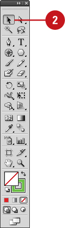
Selecting a Drawing Mode
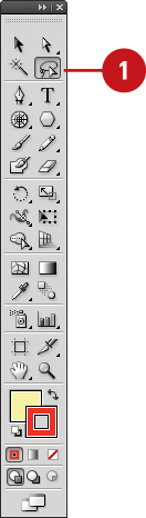
In Illustrator, you can specify how and where you want to draw an object. You can draw on top of an object, behind an object, or inside an object using one of the following drawing modes (New!): Draw Normal, Draw Behind, or Draw Inside. Draw Normal mode is the default drawing mode and the one used in previous versions of Illustrator. The Draw Behind mode allows you to draw behind all objects on a selected layer (no other objects selected). If an object is selected, the new object is drawn directly behind it. The Draw Inside mode allows you to draw inside a single selected object, which automatically creates a clipping mask from the select object. You can select a drawing mode at the bottom of the Tools panel or use the Shift+D keyboard shortcut to cycle through each one.
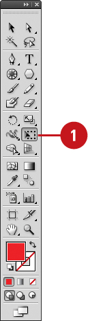
Select a Drawing Mode
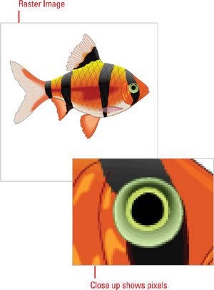
![]() Select the Drawing Mode tool on the Tools panel:
Select the Drawing Mode tool on the Tools panel:
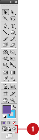
• Draw Normal. Draws an object on top of any other object; the default mode.
• Draw Behind. Draws an object behind all objects (no selection) or directly behind a selected object.
• Draw Inside. Draws an object inside a single selected object.

Timesaver
Press Shift+D to cycle through the Drawing Mode tools.
Did You Know?
You can create a clipping mask using the Draw Inside mode. Select the path you want to draw, and then click the Draw Inside mode button on the Tools panel. Subsequent paths are clipped by the selected path until you switch to the Draw Normal mode. The clipping masks created using the Draw Inside mode retain the appearance on the clipping path unlike the Make command on the Clipping Mask submenu on the Object menu.
Creating Pixel Aligned Objects
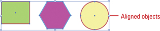
Pixel aligned vector objects (New!) allow you to create precisely drawn images that look crisp and sharp for use on different outputs, such as the Web and mobile devices. The Align to Pixel Grid option enables the vertical and horizontal segments of the paths of an object to be nudged and aligned to the pixel grid. The stroke width become full integer values to create crisp paths. To view the pixel grid, zoom to 600% or higher in Pixel Preview mode. The Align to Pixel Grid option remains enabled with the object until it’s disabled. You can set the option in the Advanced section of the New Document dialog box or the Options menu on the Transform panel. The option in the New Document dialog box, applies it any new objects in the document. You cannot pixel-align objects without paths, such as rasters, raster effects, and text objects.
Work with Pixel Aligned Objects
• Align All Objects in a New Document. Click the File menu, click New, specify new document settings, select the Align New Objects To Pixel Grid check box in the Advanced section, and then click OK.
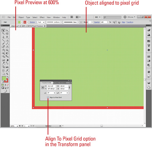
• Align Existing Objects. Select the object, open the Transform panel, and then select the Align To Pixel Grid check box.
• Not Align Objects. Select the objects you want to change, click the Select menu, point to Object, and then click Not Aligned To Pixel Grid.
• View The Pixel Grid. Click the View menu, click Pixel Preview, and then zoom to 600% or higher (New!).
• To set preferences for viewing pixel grid, click the Illustrator (Mac) or Edit (Win) menu, point to Preferences, click Guides & Grid, select the Show Pixel Grid (Above 600% Zoom) check box, and then click OK (New!).
Creating Rectangles and Ellipses
The Illustrator Tools panel includes several tools for quickly creating simple geometric vector shapes. They are easy to use; you just click and drag on the Stage to create the shapes. The Rectangle tool creates rectangles with square or rounded corners. The Ellipse tool creates circular shapes such as ovals and circles. These shapes can be comprised either of Strokes, which are lines that surround and define the shape, or Fills, which can be a color or texture inside the shape, or both.
Draw an Ellipse or Circle
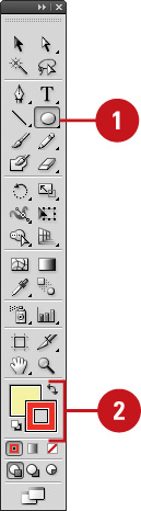
![]() Select the Ellipse tool on the Tools panel.
Select the Ellipse tool on the Tools panel.
Timesaver
Press L to select the Ellipse tool.
![]() Select a Stroke and Fill Color from the Colors area of the Tools panel.
Select a Stroke and Fill Color from the Colors area of the Tools panel.
![]() Click and drag on the artboard, and then release the mouse.
Click and drag on the artboard, and then release the mouse.
Timesaver
Press and hold Shift while you drag to create a circle.
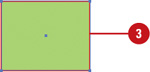
![]() To create an oval or circle with a specific width and height, click on the artboard where you want the top left corner, enter width and height values, and then click OK.
To create an oval or circle with a specific width and height, click on the artboard where you want the top left corner, enter width and height values, and then click OK.

Did You Know?
You can enter values ranging from 0 to 100 points in the Rounded Rectangle Settings dialog box. A value of zero gives you a straight-sided-square. Higher numbers produce squares with more rounded sides.
You can draw shapes without a stroke or a fill. Set either of these properties to No Fill in the Colors section of the Tools panel or in the Color panel.
Draw a Rectangle or Rounded Rectangle
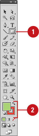
![]() Click the Rectangle or Rounded Rectangle tool on the Tools panel.
Click the Rectangle or Rounded Rectangle tool on the Tools panel.
Timesaver
Press M to select the Rectangle tool.
![]() Select a Stroke and Fill color from the Colors area of the Tools panel.
Select a Stroke and Fill color from the Colors area of the Tools panel.
![]() Click and drag on the artboard, and then release the mouse.
Click and drag on the artboard, and then release the mouse.
Timesaver
Press and hold Shift while you drag to create a square.
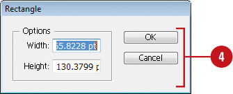
![]() To create a square, rectangle, or rounded rectangle with a specific width and height, click on the artboard where you want the top left corner, enter width and height values, and then click OK.
To create a square, rectangle, or rounded rectangle with a specific width and height, click on the artboard where you want the top left corner, enter width and height values, and then click OK.
Did You Know?
You can change the corner radius for a rounded rectangle. While you drag a rounded rectangle, press the Up Arrow or Down Arrow key. To create square corners, press the Left Arrow key. To create corners with maximum roundness, press the Right Arrow key.
You can draw shapes with no stroke or fill. If you want to draw an oval or a rectangle without a stroke or fill, you can set either of these options to No Fill in the Colors area of the Tools panel or in the Color Mixer.
You can create a flare shape using the Flare tool. Select the Flare tool on the Tools panel, click and drag on the artboard, and then release the mouse.
Creating Polygons and Stars
The Polygon and Star tools work in much the same way as the Ellipse and Rectangle tools do to allow you to easily create complex vector shapes. You can use these tools to create either polygons or stars. Polygons are shapes based on a center radius and a number of sides, while stars are shapes based on two center radiuses: one for the distance from the center of the star to the innermost points, and another for the distance from the center to the outermost points. Experiment with several options to get the kind of shape you want.
Draw a Polygon or Star Shape
![]() Select the Polygon or Star tool on the Tools panel.
Select the Polygon or Star tool on the Tools panel.

The pointer becomes a crosshair that you can drag anywhere on the artboard.
![]() Select a Stroke and Fill color from the Colors area of the Tools panel.
Select a Stroke and Fill color from the Colors area of the Tools panel.
![]() Click and drag on the artboard, and then release the mouse.
Click and drag on the artboard, and then release the mouse.

Timesaver
Press and hold Shift while you drag to create a proportional shape.
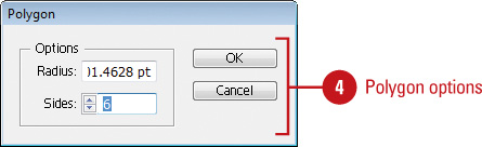
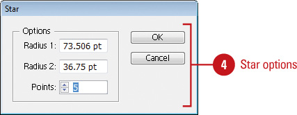
![]() To create a shape with a specific radius and number of sides or points, click on the artboard where you want the center of the shape, enter the following values, and then click OK.
To create a shape with a specific radius and number of sides or points, click on the artboard where you want the center of the shape, enter the following values, and then click OK.
• Polygon. Enter a radius and number of sides for the polygon. To create a triangle, enter 3 sides.
• Star. Enter radius 1 for the distance from the center of the star to the innermost points and enter radius 2 for the distance from the center to the outermost points.
Creating Line Segments
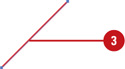
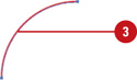
The Line Segment tool draws perfectly straight lines in any direction you drag your mouse. In Illustrator, a line is called a stroke and there is a variety of thicknesses, styles, colors, and fills that can be applied to it. You can also create your own line style for specific types of dashed, dotted or artistic lines. You can constrain the path a line draws to 45-degree angles or create closed shapes by intersecting the lines you draw.
Draw a Line Segment
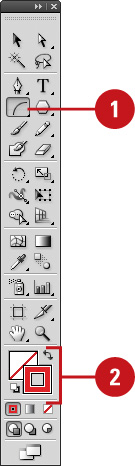
![]() Click the Line Segment tool on the Tools panel.
Click the Line Segment tool on the Tools panel.

The pointer becomes a crosshair that you can drag on the artboard.
Timesaver
Press to select the Line tool.
![]() Select a Stroke color from the Colors area of the Tools panel.
Select a Stroke color from the Colors area of the Tools panel.
![]() Click and drag on the artboard, and then release the mouse when the line is the length you need.
Click and drag on the artboard, and then release the mouse when the line is the length you need.
Timesaver
Hold down the Shift key, and then drag to draw a 45, 90, or 180 degree line.
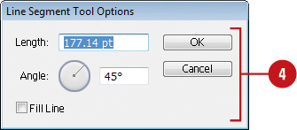
![]() To create a line with a specific length and angle, click on the artboard where you want the line to begin, enter length and angle values, select the Fill Line check box to fill the line with the current fill color, and then click OK.
To create a line with a specific length and angle, click on the artboard where you want the line to begin, enter length and angle values, select the Fill Line check box to fill the line with the current fill color, and then click OK.
Creating Arcs and Spirals
The Arc and Spiral tools make it easy to create unique and interesting shapes. These tools draw curved lines to create an individual arc or a Spiral wind. An arc consists of an x and y axis length, open or closed path, arc direction (known as the Base Along), arc slope, and arc fill (optional). A Spiral consists of a radius from the center to the outermost point in the Spiral, decay (the amount each wind decreases), number of segments for the spiral, and Spiral style. Each full wind of a Spiral consists of four segments.
Draw an Arc
![]() Click the Arc tool on the Tools panel.
Click the Arc tool on the Tools panel.
The pointer becomes a crosshair that you can drag on the artboard.
![]() Select a Stroke color from the Colors area of the Tools panel.
Select a Stroke color from the Colors area of the Tools panel.
![]() Click and drag on the artboard, and then release the mouse when the arc is the length you need.
Click and drag on the artboard, and then release the mouse when the arc is the length you need.
![]() To create an arc with specific settings, click on the artboard where you want the arc to begin, enter x and y lengths, specify type (open or closed), arc direction (Base Along) and slope options, select the Fill Arc check box to fill the arc with the current fill color, and then click OK.
To create an arc with specific settings, click on the artboard where you want the arc to begin, enter x and y lengths, specify type (open or closed), arc direction (Base Along) and slope options, select the Fill Arc check box to fill the arc with the current fill color, and then click OK.

Draw a Spiral
![]() Click the Spiral tool on the Tools panel.
Click the Spiral tool on the Tools panel.
The pointer becomes a crosshair that you can drag on the artboard.
![]() Select a Stroke color from the Colors area of the Tools panel.
Select a Stroke color from the Colors area of the Tools panel.
![]() Click and drag on the artboard, and then release the mouse when the Spiral is the length you need.
Click and drag on the artboard, and then release the mouse when the Spiral is the length you need.

![]() To create a Spiral with specific settings, click on the artboard where you want the Spiral to begin, enter a radius (distance) from the center to the outermost point, decay percentage (amount of the wind decreases), the number of segments, and style options, and then click OK.
To create a Spiral with specific settings, click on the artboard where you want the Spiral to begin, enter a radius (distance) from the center to the outermost point, decay percentage (amount of the wind decreases), the number of segments, and style options, and then click OK.

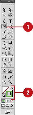
Creating Grids
The grid tools on the Tools panel allow you to create a rectangular or circular polar grid. The Rectangular Grid tool creates rectangular grids of a specified size and number of horizontal and vertical dividers. The Polar Grid tool creates concentric circles of a specified size and specific number of concentric and radial dividers.
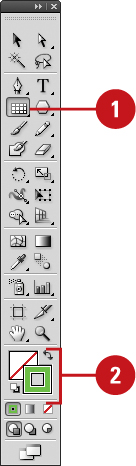
Draw Rectangle Grids
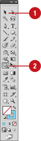
![]() Click the Rectangle Grid tool on the Tools panel.
Click the Rectangle Grid tool on the Tools panel.
The pointer becomes a crosshair that you can drag on the artboard.
![]() Select a Stroke color from the Colors area of the Tools panel.
Select a Stroke color from the Colors area of the Tools panel.
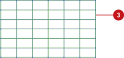
![]() Click and drag on the artboard, and then release the mouse when the grid is the size you need.
Click and drag on the artboard, and then release the mouse when the grid is the size you need.
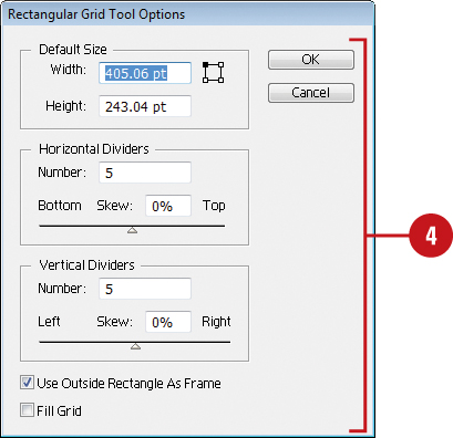
![]() To create a grid with specific settings, click on the artboard where you want the grid reference point, enter a width and height for the grid, specify the number of horizontal and vertical dividers, select the Use Outside Rectangle As Frame check box to replace individual segments with a separate rectangle object, select the Fill Grid check box to fill the grid with the current fill color, and then click OK.
To create a grid with specific settings, click on the artboard where you want the grid reference point, enter a width and height for the grid, specify the number of horizontal and vertical dividers, select the Use Outside Rectangle As Frame check box to replace individual segments with a separate rectangle object, select the Fill Grid check box to fill the grid with the current fill color, and then click OK.
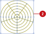
Draw Circular Polar Grids
![]() Click the Polar Grid tool on the Tools panel.
Click the Polar Grid tool on the Tools panel.

The pointer becomes a crosshair that you can drag on the artboard.
![]() Select a Stroke color from the Colors area of the Tools panel.
Select a Stroke color from the Colors area of the Tools panel.
![]() Click and drag on the artboard, and then release the mouse when the grid is the size you need.
Click and drag on the artboard, and then release the mouse when the grid is the size you need.
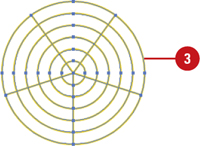
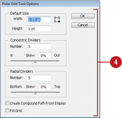
![]() To create a grid with specific settings, click on the artboard where you want the grid reference point, enter a width and height for the grid, specify the number of concentric and radial dividers, select the Create Compound Path From Ellipses check box to replace circles with separate compound paths, select the Fill Grid check box to fill the grid with the current fill color, and then click OK.
To create a grid with specific settings, click on the artboard where you want the grid reference point, enter a width and height for the grid, specify the number of concentric and radial dividers, select the Create Compound Path From Ellipses check box to replace circles with separate compound paths, select the Fill Grid check box to fill the grid with the current fill color, and then click OK.
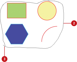
Using the Shape Builder Tool
The Shape Builder tool (New!) allows you to create complex objects by merging and erasing simpler objects. The Shape Builder tool selects edges and regions of an object, which can be merged or erased to form a new object. An edge is any section of a path that doesn’t intersect the path of other selected objects and a region is a closed area. You can also break overlapping objects to create new ones. The style attributes of an object are adopted after the merge. By default, the Shape Builder tool is in merge mode, however, you can switch to erase mode by using the Option (Mac) or Alt (Win) key. Before you start using the Shape Builder tool, you can set up and customize options, such as coloring source, highlighting, and gap detection, to suit your own preferences.
Create an Object with the Shape Builder Tool
![]() Click the Selection tool on the Tools panel, and then select only the paths you want to merge to create a shape.
Click the Selection tool on the Tools panel, and then select only the paths you want to merge to create a shape.
![]() Click the Shape Builder tool on the Tools panel. By default, merge mode is selected.
Click the Shape Builder tool on the Tools panel. By default, merge mode is selected.
![]() To break or extract a region from the shape, click the selected region.
To break or extract a region from the shape, click the selected region.

![]() To merge paths, drag along the region.
To merge paths, drag along the region.
The two regions get merged to form a new shape. The attributes from the region are applied to the merging shapes.
Timesaver
Press Shift as you drag, displays a rectangle marquee for merging multiple paths.
![]() To erase paths, press Option (Mac) or Alt (Win) and click the closed region or edge you want to delete.
To erase paths, press Option (Mac) or Alt (Win) and click the closed region or edge you want to delete.
Set Shape Builder Tool Options
![]() Double-click the Shape Builder tool on the Tools panel.
Double-click the Shape Builder tool on the Tools panel.

![]() To detect and show the gap between objects, select the Gap Detection check box, and then select a Gap Length, either Small (3 points), Medium (6 points), or Large (12 points), or select the Custom check box and specify a point size length.
To detect and show the gap between objects, select the Gap Detection check box, and then select a Gap Length, either Small (3 points), Medium (6 points), or Large (12 points), or select the Custom check box and specify a point size length.

Important
Make sure the gap length value is close to the actual gap length, otherwise Illustrator may not detect it.
![]() Specify the Options and Highlight settings you want:
Specify the Options and Highlight settings you want:
• Consider Open Filled Path as Closed. Select to create an invisible edge for an open path to make a region.
• In Merge Mode. Clicking Stroke Splits the Path. Select to split the parent path into two; the first edge you click specifies the split location.
• Pick Color From. Select Color Swatches or Artwork as the source for coloring objects. If you select Color Swatches, select the Cursor Swatch Preview check box to preview and select colors.
• Fill. Select to highlight the merged area in gray or mouse over the selected path.
• Highlight Stroke When Editable. Select to highlight strokes you can edit in the color you select.
![]() Click OK.
Click OK.
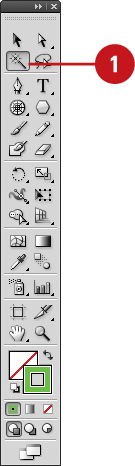
Creating Perspective Objects
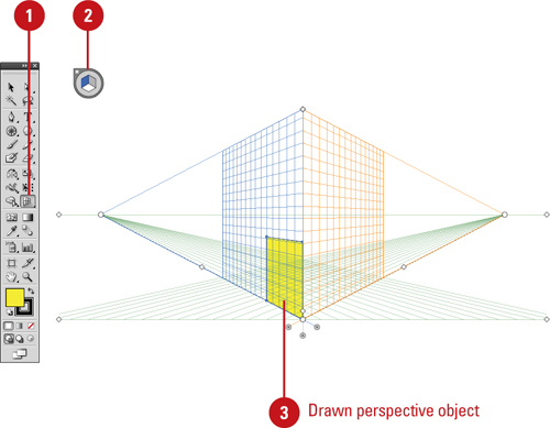
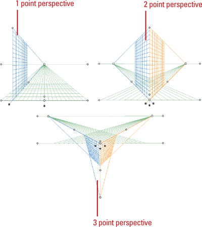
The Perspective Grid tool (New!) allows you to display a perspective grid that you can use to draw shapes and create scenes with 1, 2, or 3-point perspective. For example, you can create a row of trees down a street to create perspective. The perspective grid provides presets with a 1, 2, or 3-point perspective to help you get started. You can change the viewing angle and distance along with widgets to control vanishing points, horizon height, ground level, and the origin. You can draw objects directly on the perspective grid or attach existing ones to it. If you want to match the depth or height of an existing perspective object, you can use the Move Plane To Match Object command to adjust the grid, so you can draw or adjust another object to it.
Draw Perspective Objects
![]() Click the Perspective Grid tool on the Tools panel.
Click the Perspective Grid tool on the Tools panel.
• If the grid doesn’t appear, click the View menu, point to Perspective Grid, and then click Show Grid.
![]() To select a perspective grid preset, click the View menu, point to Perspective Grid, point to a Point Perspective (One, Two, or Three), and then select a preset.
To select a perspective grid preset, click the View menu, point to Perspective Grid, point to a Point Perspective (One, Two, or Three), and then select a preset.
![]() To draw objects on the grid, do any of the following:
To draw objects on the grid, do any of the following:
• Draw Perspective Objects. Select a Line tool (other than the Flare tool) or Rectangle tool, and then drag to draw it.
• Attach Normal Objects. Select the plane to which you want to use, select the normal object, click the Object menu, point to Perspective, and then click Attach to Active Plane.
• Release Perspective Objects. Select the attached object, click the Object menu, point to Perspective, and then click Release with Perspective.
• Move Plane to Match Objects. Select the existing object, click the Object menu, point to Perspective, and then click Move Plane To Match Object.
Adjust the Perspective Grid
![]() Click the Perspective Grid tool on the Tools panel.
Click the Perspective Grid tool on the Tools panel.
• If the grid doesn’t appear, click the View menu, point to Perspective Grid, and then click Show Grid.

![]() To select the active grid plane, click a plane in the cube (Right, Left, or Horizontal) in the Plane Switching Widget. Click the area outside the cube to select no plane.
To select the active grid plane, click a plane in the cube (Right, Left, or Horizontal) in the Plane Switching Widget. Click the area outside the cube to select no plane.
![]() To adjust the perspective grid, drag the left or right controls on the grid for any of the following:
To adjust the perspective grid, drag the left or right controls on the grid for any of the following:
• Ground Level. Moves the perspective grid.
• Vanishing Points. Adjusts the perspective in or out.
• Horizon Height. Adjusts the horizon line up or down.
• Extend the Grid. Extends or shortens the perspective grid.
• Grid Plane Controls. Adjust the Right, Horizontal, or Left.
• Grid Cell Size. Increases or decreases the grid cell size.
• Origin. Adjusts the X and Y coordinates of the grid plane.
![]() To set perspective grid related options, click the View menu, point to Perspective Grid, and then click any of the following:
To set perspective grid related options, click the View menu, point to Perspective Grid, and then click any of the following:
• Show/Hide Rulers. Shows or hides the ruler on the height line.
• Snap to Grid. Snaps an object to a perspective gridlines.
• Unlock/Lock Grid. Unlocks or locks the perspective grid.
• Lock Station Point. Locks the station point in place. When you move one vanishing point, the other one moves in sync.
Working with Perspective Objects
The Perspective Selection tool (New!) allows you to select, move, scale, copy, and transform objects in perspective. You can also add normal objects, text, and symbols to the perspective grid. When you move or change a normal object to the perspective grid, its appearance and scale change to adhere to the grid. You can select perspective objects in the grid with the Perspective Selection tool by clicking individual objects or dragging a selection marquee, just like normal objects.
Modify Perspective Objects
![]() Click the View menu, point to Perspective Grid, and then click Show Grid.
Click the View menu, point to Perspective Grid, and then click Show Grid.
![]() Click the Perspective Selection tool on the Tools panel.
Click the Perspective Selection tool on the Tools panel.

![]() To work with perspective objects on the grid, do any of the following:
To work with perspective objects on the grid, do any of the following:
• Move Perspective Objects. Select the object, and then drag it to another position or use the Arrow keys. Press tilde (~) to constrain the move to parallel.
• Move or Copy Perspective Objects and Grid Plane. Double-click a grid plane control, click the Move All Objects or Copy All Objects option, click OK, and then drag the grid plane control.
• Copy Perspective Objects. Select the object, and then Option+drag (Mac) or Alt+drag (Win) it to another position.
• Resize Perspective Objects. Select the object, and then drag a resize handle.
• Add Normal Objects. Select the active plane, and then drag the normal object to the plane.
• Add Text and Symbols. Select an existing normal text or symbol, and then drag it on the active plane. To modify the text and symbols, use the Edit Text, Edit Perspective, and Isolate Selected Object buttons on the Control panel.

Customizing a Perspective Grid
If you create your own perspective grid, you save it as a preset (New!) for use later. You can create a perspective grid by using the Define Grid command to set exacting measurements and options or by manually adjusting an existing grid, and then saving it as a preset, which you can edit at any time. When you create or work with an existing perspective grid, you can set grid options (New!) to show or hide the active plane widget, change the widget position, and specify which points you want to use to temporarily hide the active plane with the Shift key.
Set Perspective Grid Options
![]() Double-lick the Perspective Grid tool on the Tools panel.
Double-lick the Perspective Grid tool on the Tools panel.
![]() Select the Show Active Plane Widget check box to display it.
Select the Show Active Plane Widget check box to display it.

![]() Click the Widget Position list arrow, and then select a position.
Click the Widget Position list arrow, and then select a position.
![]() Select the Anchor Point Of Perspective Artwork or the Intersection Of Gridlines check boxes to specify the points where you want to temporarily hide the active plane with the Shift key.
Select the Anchor Point Of Perspective Artwork or the Intersection Of Gridlines check boxes to specify the points where you want to temporarily hide the active plane with the Shift key.
![]() Click OK.
Click OK.
Create a Perspective Grid Preset
![]() Click the View menu, point to Perspective Grid, and then click Define Grid to create a grid (steps 3 thru 6) or manually create one.
Click the View menu, point to Perspective Grid, and then click Define Grid to create a grid (steps 3 thru 6) or manually create one.
![]() Click the View menu, point to Perspective Grid, and then click Save Grid As Preset.
Click the View menu, point to Perspective Grid, and then click Save Grid As Preset.
![]() Type a name for the preset.
Type a name for the preset.
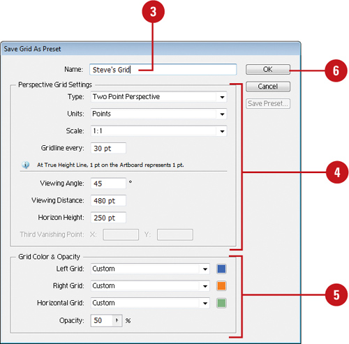
![]() Specify the perspective grid settings you want.
Specify the perspective grid settings you want.
![]() Specify the grid color & opacity settings you want.
Specify the grid color & opacity settings you want.
![]() Click OK.
Click OK.
![]() To edit a grid preset, click the Edit menu, click Perspective Grid Presets, select a preset, click Edit, make changes, and then click OK.
To edit a grid preset, click the Edit menu, click Perspective Grid Presets, select a preset, click Edit, make changes, and then click OK.
Understanding Selections
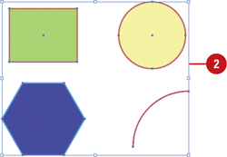
When you create vector graphics in Illustrator, they are comprised of distinct segments that can be selected separately or as a whole with a variety of selection tools. The type of editing you need to perform determines which tool you use. For example, a simple rectangle is comprised of four line segments that surround the contour of the shape and one fill in the center. Each of these parts can be selected as a group with the Selection tool or individually with the Direct Selection tool. To select an object using the fill, you need to deselect the Object Selection by Path Only check box in Selection & Anchor Display preferences. If an object is behind another object, you can use the keyboard shortcut ![]() +click (Mac) or Ctrl+click (Win) to select it (New!). The pointer changes to an arrow with a small caret on the first
+click (Mac) or Ctrl+click (Win) to select it (New!). The pointer changes to an arrow with a small caret on the first ![]() /Ctrl+click; as you continue to click the selection moves through the objects under the pointer. To use this option, you need to select the Control Click to Select Objects Behind check box in Selection & Anchor Display preferences.
/Ctrl+click; as you continue to click the selection moves through the objects under the pointer. To use this option, you need to select the Control Click to Select Objects Behind check box in Selection & Anchor Display preferences.
In addition to the Selection and Direct Selection tools, you can also use the Group Selection tool to select all the anchor points on a single path. With the Group Selection tool, click to select an object, click twice to select the object’s group, and click three times to select the group within the group (if available). The Group Selection tool is useful for working with multiple objects. If you want to work with an individual object without affecting other objects, it’s better to use Isolation Mode.
The Lasso tool is a classic selection tool that allows you to select path points and segments by dragging a freeform marquee around them.
The Magic Wand tool allows you to select objects of the same or a similar fill color, stroke color, stroke weight, opacity, or blending mode.


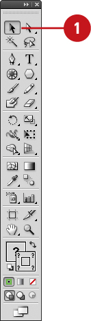
Using the Selection Tool
There are several ways to select objects in Illustrator. With the Selection tool, you can select an object’s stroke or fill. You can only select an object using the fill if the path appears in Preview mode, and the Object Selection by Path Only check box is deselected in Selection & Anchor Display preferences. After you select one or more objects, you can add or subtract objects to/from the selection. In addition, you can use the Selection tool and drag a marquee to select parts of the object or drag over a portion of it to create a selection rectangle.
Select an Object with the Selection Tool
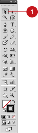
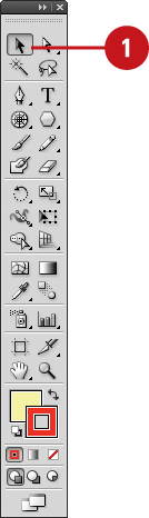
![]() Click the Selection tool on the Tools panel.
Click the Selection tool on the Tools panel.
The pointer becomes an arrow.
Timesaver
Press V to select the Selection tool.
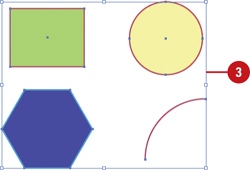
![]() Position the arrow on the edge of the object, and then click it.
Position the arrow on the edge of the object, and then click it.
• You can also drag a marquee across all or part of the object to select the entire path.
• If the path has a color fill, appears in Preview mode, and the Object Selection by Path Only check box is deselected in Selection & Anchor Display preferences, you can also click the fill to select the object.

![]() To add or subtract objects from the selection, hold down the Shift key, and then click unselected objects to add or click selected objects to subtract them from the selection.
To add or subtract objects from the selection, hold down the Shift key, and then click unselected objects to add or click selected objects to subtract them from the selection.
Using the Direct Selection Tool
With the Direct Selection tool, you can select individual points and segments of a path. After you select one or more individual points and segments, you can add or subtract items to/from the selection. In addition, you can also use the Direct Selection tool and drag a marquee to select parts of the path or drag over a portion of it to create a selection rectangle.
Select Anchor Points and Segments with the Direct Selection Tool
![]() Click the Direct Selection tool on the Tools panel.
Click the Direct Selection tool on the Tools panel.

The pointer becomes an arrow.
Timesaver
Press A to select the Direct Selection tool.
![]() Position the arrow on the edge of the path and click to select a segment, and then click an anchor point to select it.
Position the arrow on the edge of the path and click to select a segment, and then click an anchor point to select it.
• You can also select an anchor point directly. Pass the pointer over a path and then point to an anchor point and then click it.
• You can also drag a marquee across all or part of the object to select the entire path.

![]() To add or subtract anchor points or segments from the selection, hold down the Shift key, and then click unselected items to add them or selected items to subtract them from the selection.
To add or subtract anchor points or segments from the selection, hold down the Shift key, and then click unselected items to add them or selected items to subtract them from the selection.

Using the Lasso Tool
Use the Lasso tool when you want to select shapes that are very close to shapes you don’t want to select. This tool allows you to draw around the shape, selecting everything contained within the drawn area. When you draw a selection, you can drag across a path to include it in the selection instead of dragging completely around it. This selection tool is useful when you are working with overlapping paths.
Select with the Lasso Tool
![]() Click the Lasso tool on the Tools panel.
Click the Lasso tool on the Tools panel.
![]() Draw around the shapes you want to select.
Draw around the shapes you want to select.
![]() To complete the selection, return to the point where you started.
To complete the selection, return to the point where you started.
Did You Know?
You can select single or multiple objects. Holding the Shift key adds line segments and fills them. Shift-clicking selected items deselects them.
Using the Magic Wand Tool
The Magic Wand tool (so named since it looks like a magic wand) is unique in the fact that you do not drag and select with this tool; you simply click. The Magic Wand tool creates a selection based on the shift in brightness ranges within an image. If there is a definable shift in the brightness of the pixels, it can be a very powerful tool for the selection of odd-shaped areas. To use the Magic Wand, click on the Magic Wand Tool button on the Tools panel.
Select Options for the Magic Wand Tool
![]() Double-click the Magic Wand tool on the Tools panel.
Double-click the Magic Wand tool on the Tools panel.
• You can also click the Window menu, and then click Magic Wand to display the panel.

![]() Click the Options menu, and then select the Show Stroke Options and Show Transparency Options (if necessary) to display them in the Magic Wand panel.
Click the Options menu, and then select the Show Stroke Options and Show Transparency Options (if necessary) to display them in the Magic Wand panel.
• You can also click the double-arrow next to the Magic Wand title to display options.

![]() Select the check box for the attributes that you want the Magic Wand to select. The options include: Fill Color, Stroke Color, Stroke Weight, Opacity, or Blending Mode.
Select the check box for the attributes that you want the Magic Wand to select. The options include: Fill Color, Stroke Color, Stroke Weight, Opacity, or Blending Mode.

![]() Enter a Tolerance value (0 to 255). The higher the value, the more information the Magic Wand tool selects.
Enter a Tolerance value (0 to 255). The higher the value, the more information the Magic Wand tool selects.
![]() To select objects on all layers, click the Options menu, and then select Use All Layers to check it. Select it again to select objects only on the current layer.
To select objects on all layers, click the Options menu, and then select Use All Layers to check it. Select it again to select objects only on the current layer.
![]() To reset all fields in the Magic Wand panel, click the Options menu, and then click Reset.
To reset all fields in the Magic Wand panel, click the Options menu, and then click Reset.
Use the Magic Wand Tool
![]() Select the Magic Wand tool on the Tools panel.
Select the Magic Wand tool on the Tools panel.
![]() Click an object area to make a selection.
Click an object area to make a selection.

Depending on the options you selected in the Magic Wand panel, other objects with the same or similar attributes (fill color, stroke color, stroke weight, opacity, or blending mode) are selected.
![]() To add to the selection, hold down the Shift key, and then click another unselected object.
To add to the selection, hold down the Shift key, and then click another unselected object.
To subtract from the selection, hold down the Alt (Win) or Option (Mac) key, and then click a selected object.
Selecting and Grouping Objects
Selecting and grouping objects makes it easier to work with multiple objects as if they were a single object. You can easily select, isolate, cut, copy, paste, move, recolor, and transform a grouped object. You can group all types of objects, yet still edit individual objects within the group as needed without having to ungroup them first by using Isolation Mode. Illustrator places a grouped object on the top level of the top object in the group and uses the same selection color. If you no longer need to group objects, you can ungroup them.
Create a Group
![]() Select the Selection tool on the Tools panel.
Select the Selection tool on the Tools panel.
![]() Use a selection method to select the objects that you want in the group.
Use a selection method to select the objects that you want in the group.

![]() Click the Objects menu, and then click Group.
Click the Objects menu, and then click Group.
• You can use the Group command again to group objects already in a group; this is known as a nested group.
Ungroup Objects
![]() Select the Selection tool on the Tools panel.
Select the Selection tool on the Tools panel.

![]() Select the grouped objects that you want to ungroup.
Select the grouped objects that you want to ungroup.
![]() Click the Objects menu, and then click Ungroup.
Click the Objects menu, and then click Ungroup.
• If you have nested groups within an object, you can use the Ungroup command again to ungroup it.
Use Isolation Mode to Work with Groups
![]() Select the Selection tool on the Tools panel.
Select the Selection tool on the Tools panel.
![]() Double-click a grouped object.
Double-click a grouped object.
• You need to click the Isolate Selected Group button on the Control panel or select the Double-click to Isolate check box in General preferences.
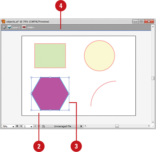
A gray bar appears with the name of the group at the top of the document window. All objects outside the group are dimmed out and uneditable. The words “Isolation Mode” also appear on the Layers panel.
![]() Edit individual objects or add new objects to the group.
Edit individual objects or add new objects to the group.
![]() To exit Isolation Mode, click the gray bar.
To exit Isolation Mode, click the gray bar.
Selecting Similar Objects
The Select menu provides a variety of powerful selection commands for you to use in a document or artboard. In addition to the common commands, such as All, Deselect, and Inverse, you can also select objects whose attributes (including Appearance, Blending Modes, Fill & Stroke, Opacity, and Stroke Color) are similar to the current or last selection. For more selection power, you can select objects based on the object type (including All on Same Layers, Direction Handles, Brush Strokes, Clipping Masks, Stray Points, Text Objects).
Use the Select Menu to Select Objects
![]() Click the Select menu.
Click the Select menu.
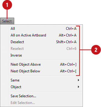
![]() Select the command that you want:
Select the command that you want:
• All. Selects all objects in the document.
• All on Active Artboard. Selects all objects in the active artboard.
• Deselect. Deselects all objects in the document.
• Reselect. Reselects the most recent selection.
• Inverse. Inverses the current selection.
• Next Object Above. Selects the next object above the current selection.
• Next Object Below. Selects the next object below the current selection.
Select Similar Objects or Object Attributes
![]() Select an object on which to base the new selection or deselect all objects to base the new selection on the last selected object.
Select an object on which to base the new selection or deselect all objects to base the new selection on the last selected object.
![]() Click the Select menu, and then point to Same or Object.
Click the Select menu, and then point to Same or Object.
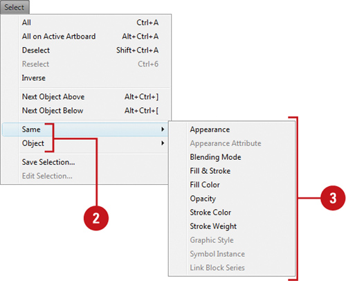
![]() Choose the command that you want to use to make a selection.
Choose the command that you want to use to make a selection.
Select Objects in the Layers Panel
![]() Open the Layers panel.
Open the Layers panel.

![]() Click the expand/collapse triangle to display the layer that you want to select.
Click the expand/collapse triangle to display the layer that you want to select.
![]() Click the selection area on the right side of the layer in the Layers panel that has the object that you want to select.
Click the selection area on the right side of the layer in the Layers panel that has the object that you want to select.
• You can also click the Select menu, point to Object, and then click All on Same Layers to select all on a layer.

Saving and Editing Selections
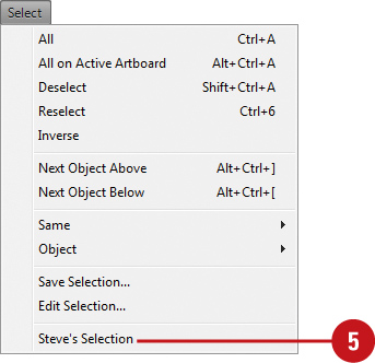
If you frequently select the same elements in a document, you can save yourself some time by saving the selection with a name of your choice. After you save a selection, the saved selection name appears as a menu command at the bottom of the Select menu. When you need to make the same selection, simply choose the command. When you no longer use a saved selection, you can delete it.
Save and Use a Selection
![]() Make the selection that you want to save.
Make the selection that you want to save.
![]() Click the Select menu, and then click Save Selection.
Click the Select menu, and then click Save Selection.
![]() Enter a name for the selection.
Enter a name for the selection.

![]() Click OK.
Click OK.
![]() Click the Select menu, and then click the name of the saved selection at the bottom of the menu.
Click the Select menu, and then click the name of the saved selection at the bottom of the menu.
Edit a Saved Selection
![]() Click the Select menu, and then click Edit Selection.
Click the Select menu, and then click Edit Selection.
![]() Select the saved selection that you want to rename or delete.
Select the saved selection that you want to rename or delete.

![]() To delete a saved selection, click Delete.
To delete a saved selection, click Delete.
![]() To rename a saved selection, change the name in the Name box.
To rename a saved selection, change the name in the Name box.
![]() Click OK.
Click OK.
Moving Objects
Moving an object or group of objects is very easy. The simplest way is to drag the edge of an object in Outline or Preview view. If you want to constrain the movement of the object in multiples of 45 degrees, then use the Shift key as you drag. While you drag an object, Smart Guides appear automatically to make it easier for you to align objects with other objects.
Move an Object
![]() Select the Selection tool on the Tools panel.
Select the Selection tool on the Tools panel.

![]() Select one or more objects that you want to move.
Select one or more objects that you want to move.
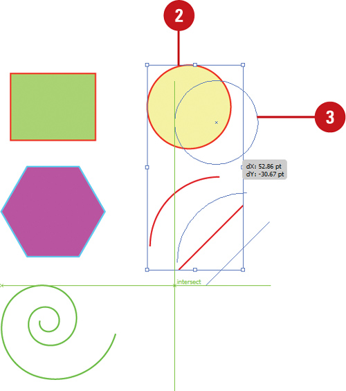
![]() Drag the edge of an object.
Drag the edge of an object.
• To constrain the movement of the object to multiples of 45 degrees or the current angle in General preferences, hold down the Shift key as you drag.
• If the path has a color fill, appears in Preview mode, and the Object Selection by Path Only check box is deselected in Selection & Anchor Display preferences, you can also click the fill to select the object.
Did You Know?
You can delete an object. Select the object that you want to delete, and then press Delete, or click the Edit menu, and then click Clear.
See Also
See “Using Smart Guides” on page 50 for more information on setting Smart Guide preferences and using Smart Guides.
Duplicating Objects
Duplicating objects can be a powerful way of creating geometrical artwork. You can duplicate one or more selected objects by dragging them, using Arrow keys, copying to and pasting from the Clipboard, or using the Offset Path command. When you copy objects to the Clipboard, you can paste them on an artboard several different ways: Paste, Paste in Front, Paste in Back, Paste in Place (New!), or Paste on All Artboards (New!). The Offset Path command duplicates a path (along with fill and stroke attributes) and places it on the artboard based on the offset distance specified in the Offset Path dialog box. The duplicate path is reshaped to fit around the original path.
Duplicate or Copy Objects
![]() Select the Selection tool on the Tools panel.
Select the Selection tool on the Tools panel.
• If the object is in a group, select the Direct Selection tool on the Tools panel.

![]() Use any of the following methods:
Use any of the following methods:
• Same Document. Hold down Alt (Win) or Option (Mac), and then drag the edge or fill of the object.
• Different Documents. Open the documents side by side, and then drag the edge or fill of the object from one document to another.
• Copy/Paste from Clipboard. Select the object, click the Edit menu, and then click Copy. Click in the target document or artboard, click the Edit menu, and then click Paste, Paste in Front, Paste in Back, Paste in Place (New!), or Paste on All Artboards (New!).
• Keyboard. Select the object, press Control (Win) or ![]() (Mac), and then use an Arrow key to move the duplicated object in the direction you want. The duplicate object moves away from the original object based on the current keyboard increment value in General preferences.
(Mac), and then use an Arrow key to move the duplicated object in the direction you want. The duplicate object moves away from the original object based on the current keyboard increment value in General preferences.

Duplicate Objects Using an Offset
![]() Select the Selection tool on the Tools panel.
Select the Selection tool on the Tools panel.

![]() Select an object.
Select an object.
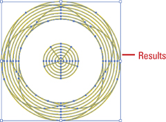
![]() Click the Object menu, point to Path, and then click Offset Path.
Click the Object menu, point to Path, and then click Offset Path.
![]() Enter the distance you want to offset the duplicate path from the original object.
Enter the distance you want to offset the duplicate path from the original object.
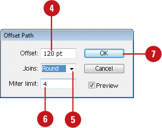
![]() Click the Joins list arrow, and then select a bend style: Miter (pointed), Round (circular), or Bevel (square-cornered).
Click the Joins list arrow, and then select a bend style: Miter (pointed), Round (circular), or Bevel (square-cornered).
![]() You can set a limit (1-500) to determine when a mitered corner changes into a beveled corner. A low number creates a more beveled corner, while a high number creates a sharper corner.
You can set a limit (1-500) to determine when a mitered corner changes into a beveled corner. A low number creates a more beveled corner, while a high number creates a sharper corner.
![]() Click OK.
Click OK.
Aligning and Distributing Objects
In addition to using grids and guides to align objects to a specific point, you can align a group of objects to each other. The Align panel buttons make it easy to align two or more objects relative to each other or to the page. To evenly align several objects to each other across the document, either horizontally or vertically, select them and then choose a distribution option. Before you select an align command, specify how you want Illustrator to align the objects. You can align the objects in relation to the document or to the selected objects. If you want to align all the objects to another object, you can select and use a key object, before you select an alignment option.
Align or Distribute Objects
![]() Select the Selection tool on the Tools panel.
Select the Selection tool on the Tools panel.
![]() Select two or more objects to align them or select three or more objects to distribute them.
Select two or more objects to align them or select three or more objects to distribute them.

![]() Select the Align panel or click Align on the Control panel.
Select the Align panel or click Align on the Control panel.

![]() Click the Options menu, and then click Use Preview Bounds. A checked option uses the object’s stroke weight and any applied effects when aligning or distributing.
Click the Options menu, and then click Use Preview Bounds. A checked option uses the object’s stroke weight and any applied effects when aligning or distributing.
![]() If you want to align objects along the edges of the artboard, click the Align To menu on the Align or Control panel, and then click Align to Artboard. Objects are moved on the artboard based on the alignment or distribution command to the closest edge (top and bottom, or left and right).
If you want to align objects along the edges of the artboard, click the Align To menu on the Align or Control panel, and then click Align to Artboard. Objects are moved on the artboard based on the alignment or distribution command to the closest edge (top and bottom, or left and right).
![]() If you want to align objects to a key object, click an object to make it the key object (a thick blue outline appears and the Align To Key Object option is selected in the Align and Control panel).
If you want to align objects to a key object, click an object to make it the key object (a thick blue outline appears and the Align To Key Object option is selected in the Align and Control panel).
![]() Use the alignment and distribution buttons on the Align or Control panel.
Use the alignment and distribution buttons on the Align or Control panel.
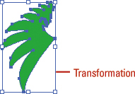
Transforming Objects
The easiest way to transform an object is to use the bounding box. With the bounding box, you can quickly scale (resize), reflect (mirror), and rotate an object. However, you cannot copy an object or move the reference point. As you drag to transform an object, you can use keyboard keys to alter the results of a transformation. Experiment with the different options to create some new results.
Transform an Object with the Bounding Box
![]() Click the View menu, and then click Show Bounding Box to display it.
Click the View menu, and then click Show Bounding Box to display it.
![]() Select the Selection tool on the Tools panel.
Select the Selection tool on the Tools panel.
![]() Select one or more objects to transform.
Select one or more objects to transform.

![]() Use any of the following methods:
Use any of the following methods:
• Scale. Drag a corner handle to scale along two axes; drag a side handle to scale along one axis; Shift-drag to scale proportionally; hold down Alt (Win) or Option (Mac), and then drag to scale from the center. Also hold down Shift to scale from the center proportionally.
• Reflect. Drag a side handle all the way across the object to the other side.
• Rotate. Point slightly outside a corner handle (pointer changes to a double arrow), and then drag in a circular motion.
To rotate an object 180 degrees, drag a corner handle diagonally all the way across the object.
![]() To transform an object using exact values or percentages, select the Transform panel.
To transform an object using exact values or percentages, select the Transform panel.
Using the Free Transform Tool
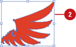
The Free Transform tool allows you to rotate, scale (resize), reflect (mirror image), or shear (slant) an object. In addition, you can apply perspective and distortion to an object. However, you cannot copy an object or move the reference point. As you drag to transform an object, you can use keyboard keys to alter the results of a transformation. To help you align the results the way you want, you can use Smart Guides to make it easier.
Transform an Object with the Free Transform Tool
![]() Select the Free Transform tool on the Tools panel.
Select the Free Transform tool on the Tools panel.
![]() Select one or more objects to transform.
Select one or more objects to transform.
![]() Use any of the following methods:
Use any of the following methods:
• Scale. Drag a corner handle to scale along two axes; drag a side handle to scale along one axis; Shift-drag to scale proportionally; hold down Alt (Win) or Option (Mac), and then drag to scale from the center. Also hold down Shift to scale from the center proportionally.
• Reflect. Drag a side handle all the way across the object to the other side.
• Rotate. Point slightly outside a corner handle (pointer changes to a double arrow), and then drag in a circular motion. To rotate in 45 degree increments, Shift-drag.
To rotate an object 180 degrees, drag a corner handle diagonally all the way across the object.
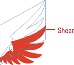
• Shear. Drag a side handle and then hold down Ctrl (Win) or ![]() (Mac) as you continue to drag. To constrain the movement, also press Shift. To shear from the center, also press Alt (Win) or Option (Mac).
(Mac) as you continue to drag. To constrain the movement, also press Shift. To shear from the center, also press Alt (Win) or Option (Mac).

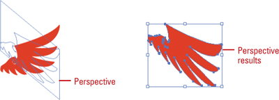
• Perspective. Drag a side handle and then hold down Ctrl+Alt+Shift (Win) or ![]() +Option+Shift (Mac) as you continue to drag.
+Option+Shift (Mac) as you continue to drag.
• Distort. Drag a corner handle and then hold down Ctrl (Win) or ![]() (Mac) as you continue to drag.
(Mac) as you continue to drag.
![]() To use Smart Guides as you transform an object:
To use Smart Guides as you transform an object:
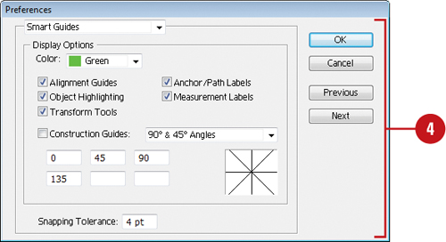
• Select the Transform Tools check box in Smart Guides preferences.
• Click the View menu, and then click Smart Guides to display them.
• As you drag to transform an object, smart guides appear in your document, which you can use to align the transformed object.
![]() To transform an object using exact values or percentages, select the Transform panel.
To transform an object using exact values or percentages, select the Transform panel.
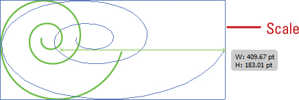
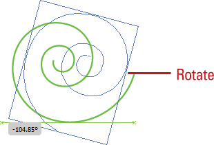
Rotating and Scaling Objects
After you create an object, you can change its orientation by rotating it or change its size by scaling it. For a freeform rotation, when you want to rotate the object in other than 90 or 180 degree increments, you can use the Rotate tool. To resize an object, either smaller or larger, you can use the Scale tool. With either tool, you can transform the object from its center or the reference point. To rotate or scale an object using exact values or percentages, use the Transform panel, which is available on the Control panel or Window menu.
Rotate or Scale an Object
![]() Select the Selection tool on the Tools panel.
Select the Selection tool on the Tools panel.

![]() Select one or more objects to transform.
Select one or more objects to transform.
![]() Select the Rotate or Scale tool on the Tools panel.
Select the Rotate or Scale tool on the Tools panel.
![]() To move the reference point, click a new point.
To move the reference point, click a new point.
![]() Use the appropriate method:
Use the appropriate method:
• Rotate. Drag in a circular motion. To rotate in 45 degree increments, Shift-drag.
• Scale. Drag away from or toward the object. Shift-drag to scale proportionally; hold down Alt (Win) or Option (Mac), and then drag to scale from the center. Also hold down Shift to scale from the center proportionally.
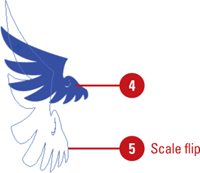
• Scale and Flip. Drag across the entire object.
• Scale and Copy. Hold down Alt+Shift (Win) or Option+Shift (Mac), and then drag.
![]() To rotate or scale an object using exact values or percentages, select the Transform panel.
To rotate or scale an object using exact values or percentages, select the Transform panel.
Reflecting and Shearing Objects
The Reflect and Shear tools on the Tools panel allow you to be creative as you transform an object. The Reflect tool creates a mirror image of an object, while the Shear tool creates a slanted image of an object. To reflect or shear an object using exact values or percentages, open the Transform panel, which is available on the Control panel or Window menu.
Reflect or Shear an Object
![]() Select the Selection tool on the Tools panel.
Select the Selection tool on the Tools panel.

![]() Select one or more objects to transform.
Select one or more objects to transform.
![]() Select the Reflect or Shear tool on the Tools panel.
Select the Reflect or Shear tool on the Tools panel.
![]() To move the reference point, click a new point.
To move the reference point, click a new point.

![]() Use the appropriate method:
Use the appropriate method:
• Reflect. Click to establish a reference point, and then click again to establish the axis of reflection.
• Shear. Drag away from the object.
![]() To reflect or shear an object using exact values or percentages, select the Transform panel.
To reflect or shear an object using exact values or percentages, select the Transform panel.
Applying Multiple Transformations
The Transform Each command allows you to transform multiple objects relative to their individual reference points instead of a single reference point. With the Transform Each command, you can scale or move objects horizontally or vertically, rotate objects by a specific angle, and create a mirror reflection of the objects. If you want to create a unique effect, you can also have Illustrator apply random transformations. You can also use the Transform Effect command to create similar effects, which you can modify.
Use the Transform Each Command
![]() Select the Selection tool on the Tools panel.
Select the Selection tool on the Tools panel.
![]() Select one or more objects to transform.
Select one or more objects to transform.
![]() Click the Object menu, point to Transform, and then click Transform Each.
Click the Object menu, point to Transform, and then click Transform Each.
![]() Select the Preview check box to view your changes on the selected object.
Select the Preview check box to view your changes on the selected object.
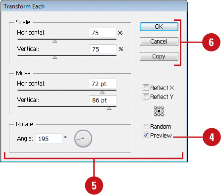
![]() Do any of the following:
Do any of the following:
• Scale Horizontal or Vertical. Drag the slider or enter a percentage to scale objects from their reference point.
• Move Horizontal or Vertical. Drag the slider or enter a percentage to move objects left or right and up or down.
• Rotate Angle. Enter a rotate angle or drag the dial.
• Reflect X or Y. Select to create a mirror reflection of the objects.
• Reference Point. Click a square to change the reference point.
• Random. Select to apply random transformations using the values in the dialog box.
![]() Click OK or Copy (creates a copy and applies the transformation).
Click OK or Copy (creates a copy and applies the transformation).
Use the Transform Effect
![]() Select the Selection tool on the Tools panel.
Select the Selection tool on the Tools panel.
![]() Select one or more objects to transform.
Select one or more objects to transform.

![]() Click the Effect menu, point to Distort & Transform, and then click Transform.
Click the Effect menu, point to Distort & Transform, and then click Transform.
![]() Select the Preview check box to view your changes on the selected object.
Select the Preview check box to view your changes on the selected object.

![]() Do any of the following:
Do any of the following:
• Scale Horizontal or Vertical. Drag the slider or enter a percentage to scale objects from their reference point.
• Move Horizontal or Vertical. Drag the slider or enter a percentage to move objects left or right and up or down.
• Rotate Angle. Enter a rotate angle or drag the dial.
• Copies. Enter the number of copies you want.
• Reflect X or Y. Select to create a mirror reflection of the objects.
• Reference Point. Click a square to change the reference point.
• Random. Select to apply random transformations using the values in the dialog box.
![]() Click OK.
Click OK.
![]() To edit the transformation, select the object, and then click Transform on the Appearance panel.
To edit the transformation, select the object, and then click Transform on the Appearance panel.
For Your Information: Repeating a Transformation
The Transform Again command allows you to quickly repeat the last transformation with the last-used values on a selected object. To use the command, transform and select an object or group, click the Object menu, point to Transform, and then click Transform Again or press Ctrl+D (Win) or ![]() +D (Mac).
+D (Mac).
Reshaping Objects with Envelopes
Envelopes are objects you can use to reshape other objects, except graphs, guides, or linked objects. You can use one of the built-in envelopes or create your own out of an existing object. The built-in envelopes use warp shapes or a mesh grid as the object. After you apply an envelope, you can edit the original object or the envelope (anchor points), separately, using the Selection and Mesh tools on the Tools panel.
Distort Objects with an Envelope
![]() Select the Selection tool on the Tools panel.
Select the Selection tool on the Tools panel.
![]() Select one or more objects to reshape.
Select one or more objects to reshape.

![]() Click the Object menu, point to Envelope Distort, and then click one of the following:
Click the Object menu, point to Envelope Distort, and then click one of the following:
• Make With Warp. Uses a preset warp shape.
• Make with Mesh. Uses a rectangle grid.
• Make With Top Object. Uses an object as the shape of the envelope. The object needs to be at the top of the stacking order.
![]() Specify the options you want for the envelope type; select the Preview check box to view your changes on the selected object.
Specify the options you want for the envelope type; select the Preview check box to view your changes on the selected object.
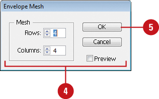
![]() Click OK.
Click OK.
![]() Do any of the following:
Do any of the following:
• Reshape. Select the Selection or Mesh tool, and then drag any anchor points.
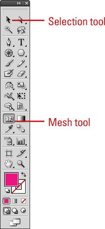
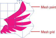
• Delete Anchor Points. For a mesh grid, select the Selection or Mesh tool, select an anchor point, and then press Delete.
• Add Anchor Points. For mesh grid, select the Mesh tool, and then click on the grid.