 Wheeled Mobile Robotics
by Igor Skrjanc, Saso Blazic, Andrej Zdesar, Gregor Klancar
Wheeled Mobile Robotics
Wheeled Mobile Robotics
by Igor Skrjanc, Saso Blazic, Andrej Zdesar, Gregor Klancar
Wheeled Mobile Robotics
- Cover image
- Title page
- Table of Contents
- Copyright
- Preface
- Acknowledgements
- Chapter 1: Introduction to Mobile Robotics
- Chapter 2: Motion Modeling for Mobile Robots
- Chapter 3: Control of Wheeled Mobile Systems
- Chapter 4: Path Planning
- Chapter 5: Sensors Used in Mobile Systems
- Chapter 6: Nondeterministic Events in Mobile Systems
- Chapter 7: Autonomous Guided Vehicles
- Chapter 8: Project Examples for Laboratory Practice
- Abstract
- 8.1 Introduction
- 8.2 Localization Based on Bayesian Filter Within a Network of Paths and Crossroads
- 8.3 Localization Based on Extended Kalman Filter Using Indoor Global Positioning System and Odometry
- 8.4 Particle-Filter-Based Localization in a Pattern of Colored Tiles
- 8.5 Control of Vehicles in a Linear Formation
- 8.6 Motion and Strategy Control of Multiagent Soccer Robots
- 8.7 Image-Based Control of a Mobile Robot
- 8.8 Particle-Filter-Based Localization Using an Array of Ultrasonic Distance Sensors
- 8.9 Path Planning of a Mobile Robot in a Known Environment
- Index
Example 3.17
Compute the optimal velocity profile that will result in the shortest traveling time for a given path ![]() ,
, ![]() where u ∈ [0, 2π] and considering maximal tangential accelerations aMAXt = 2 m/s2 and radial acceleration aMAXr = 4 m/s2.
where u ∈ [0, 2π] and considering maximal tangential accelerations aMAXt = 2 m/s2 and radial acceleration aMAXr = 4 m/s2.
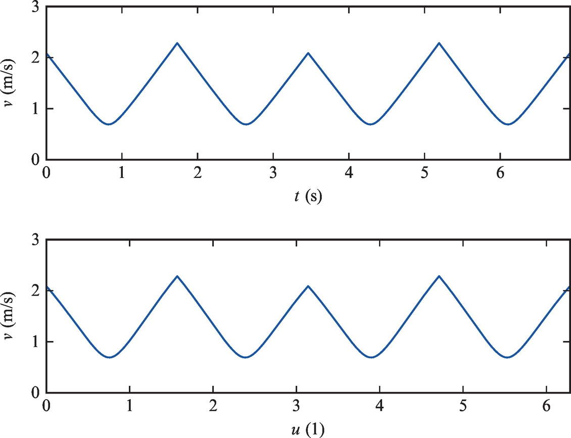
Compute the schedule u(t) and velocity profiles v(u), v(t).
Solution
To compute the optimal schedule u(t) the algorithm presented in this chapter needs to be implemented. First the TPs need to be computed with the initial conditions given in relations (3.119), (3.123); then the solutions for each TP are simulated using Eq. (3.122). Finally, the time derivative of the schedule is minimized according to Eq. (3.125).
A possible implementation of the solution is given in Listing 3.16 (neglect code clocks that could be evaluated if the variable velCnstr would be set to true). Optimum schedule determination of Example 3.17 is given in Figs. 3.39–3.41. In Fig. 3.39 it can be seen that solution for each TP is integrated up to the point where the acceleration constraints are violated, which is marked with a thin line. The final solution is marked with a thick line.

 of all the turn points.

Listing 3.16
1 % Define trajectory with function handles
2 x = @(u) cos(u) ; y = @(u) sin(2*u) ; % Path
3 dx = @(u) − sin ( u ) ; dy = @(u) 2*cos(2*u) ; % First derivative
4 ddx = @(u) − cos ( u ) ; ddy = @(u) −4* sin (2* u ) ; % Second derivative
5 v = @(u) sqrt(dx(u) .ˆ2 + dy(u) .ˆ2) ; % Tangential velocity
6 w = @(u) (dx(u) .* ddy(u)− dy ( u ) .* ddx ( u ) ) . / ( dx(u) .ˆ2+dy(u) .ˆ2) ; % Angular vel.
7 kappa = @(u) w(u) ./ v(u) ; % Curvature
8
9 u = 0:0.001:2*pi; % Time
10 arMax = 4; atMax = 2; % Acceleration constraints
11 vSP = 0 . 2 ; vEP = 0 . 1 ; % Initial and f i n a l velocity requirements
12 uSP = u(1) ; uEP = u(end) ; % Start point and end point
13 uTP = [ ] ; % Turn points
14 for i = 2:length(u)−1 % Determine turn points
15 if a l l (abs(kappa(u( i ) ) ) > abs(kappa(u ( [ i −1, i +1]) ) ) )
16 uTP = [ uTP , u ( i ) ] ;
17 end
18 end
19 up0 = sqrt(arMax ./abs(v(uTP) .*w(uTP) ) ) ; % Derivative in turn points
20
21 velCnstr = false ; % Enable velocity contraints (disabled)
22 if velCnstr
23 vMax = 1.5* inf ; % Velocity constraints
24 for i = 1:length(uTP) % Make uTP in accordance with velocity constraint
25 vvu = v(uTP( i ) ) ; vvt = vvu*up0( i ) ;
26 if abs( vvt ) > vMax, up0( i ) = abs(vMax/vvu) ; end
27 end
28 % Add requirements for Initial and f i n a l velocity
29 uTP = [uSP, uTP, uEP ] ; up0 = [ vSP/v(uSP) , up0 , vEP/v(uEP) ] ;
30 end
31
32 Ts = 0.001; % Simulation sampling time
33 N = length(uTP) ; ts = c e l l (1 ,N) ; us = c e l l (1 ,N) ; ups = c e l l (1 ,N) ;
34 for i = 1:N % Loop through a l l turn points
35 uB = uTP( i ) ; upB = up0( i ) ; tB = 0;
36 uF = uTP( i ) ; upF = up0( i ) ; tF = 0;
37 uBs =[]; upBs = [ ] ; tBs = [ ] ; uFs = [ ] ; upFs =[]; tFs = [ ] ; % Storage
38 goB = true ; goF = true ;
39
40 while goB || goF
41 % Integrate back from the turn point
42 if uB > uSP && goB
43 dxT = dx(uB) ; dyT = dy(uB) ;
44 ddxT = ddx(uB) ; ddyT = ddy(uB) ;
45 vT = v(uB)*upB; wT = w(uB)*upB; kappaT = kappa(uB) ;
46 arT = vT* wT; atT = atMax*sqrt(1 − ( arT / arMax ) ˆ2) ;
47
48 if velCnstr && abs(vT) > vMax
49 upB = vMax/v(uB) ; upp = 0;
50 else i f abs(arT)− arMax > 0.001
51 arT = arMax ; atT = 0; upp = 0; goB = false ;
52 else
53 atT = − r e a l ( atT ) ;
54 upp = real(− atMax * sqrt(1/(dxTˆ2 + dyTˆ2) − . . .
55 (dxTˆ2 + dyTˆ2)*kappaTˆ2*upBˆ4/arMaxˆ2) − . . .
56 (dxT*ddxT + dyT*ddyT) /(dxTˆ2 + dyTˆ2) * upBˆ2) ;
57 end
58
59 uBs = [ uBs ; uB ] ; upBs = [ upBs ; upB ] ; tBs = [ tBs ; tB ] ; % Store
60 tB = tB + Ts ;
61 uB = uB − upB * Ts ; % Euler integration
62 upB = upB − upp * Ts ; % Euler integration
63 else
64 goB = false ;
65 end
66
67 % Integrate forward from the turn point
68 if uF < uEP && goF
69 (dxT = dx(uF) ; dyT = dy(uF) ;
70 (ddxT = ddx(uF) ; ddyT = ddy(uF) ;
71 vT = v(uF)*upF ; wT = w(uF)*upF ; kappaT = kappa(uF) ;
72 arT = vT* wT; atT = atMax*sqrt(1 − ( arT / arMax ) ˆ2) ;
73
74 if velCnstr && abs(vT) > vMax
75 upF = vMax/v(uF) ; upp = 0;
76 else i f abs(arT)− arMax > 0.001
77 arT = arMax ; atT = 0; upp = 0; goF = false ;
78 else
79 atT = real(atT) ;
80 upp = real(+atMax*sqrt(1/(dxTˆ2 + dyTˆ2) − . . .
81 (dxTˆ2 + dyTˆ2)*kappaTˆ2*upFˆ4/arMaxˆ2) − . . .
82 (dxT*ddxT + dyT*ddyT) /(dxTˆ2 + dyTˆ2) * upFˆ2) ;
83 end
84
85 uFs = [ uFs ; uF ] ; upFs = [ upFs ; upF ] ; tFs = [ tFs ; tF ] ; % Store
86 tF = tF + Ts ;
87 uF = uF + upF*Ts ; % Euler integration
88 upF = upF + upp*Ts ; % Euler integration
89 else
90 goF = false ;
91 end
92 end
93
94 ts { i } = [ tBs ; tB +tFs (2:end) ] ;
95 us{ i } = [flipud(uBs) ; uFs (2:end) ] ;
96 ups{ i } = [flipud(upBs) ; upFs (2:end) ] ;
97 end
98
99 % Find minimum of a l l p r o f i l e s ups (schedule derivative)
100 usOrig = us ;
101 for i = 1:N−1
102 d = ups { i +1} − interp1 ( us{ i } , ups{ i } , us{ i +1}) ;
103 j = find(d (1:end−1) .* d ( 2 : end ) <0, 1) ; % Where ups{i} i s approx. ups{i+1}
104 % Find more exact u where p r o f i l e s ups{i} and ups{i+1} are equal
105 uj = us{ i +1}( j ) + ( us{ i +1}( j +1) − us { i +1}( j ) ) /( d ( j +1) − d ( j ) ) *(0− d ( j ) ) ;
106 rob = interp1( us{ i } , ups{ i } , uj ) ;
107
108 keep = us{ i } < uj ;
109 us{ i } = [ us{ i }( keep ) ; uj ] ; ups{ i } = [ ups{ i }( keep ) ; rob ] ;
110 keep = us{ i +1} > uj ;
111 us{ i +1} = [ uj ; us{ i +1}(keep ) ] ; ups{ i +1} = [ rob ; ups{ i +1}(keep ) ] ;
112 end
113
114 % Construct f i n a l solution p r o f i l e
115 tt = interp1( usOrig {1} , ts {1} , us {1}) ; uu = us {1}; uup = ups {1};
116 for i = 2:N
117 t i = interp1( usOrig{ i } , ts { i } , us{ i }) ;
118 tt = [ tt ; t i + tt (end) − t i (1) ] ;
119 uu = [ uu ; us{ i } + uu(end) − us { i }(1) ] ;
120 uup = [ uup ; ups{ i } ] ;
121 end
122 vv = v(uu) .* uup ;
Example 3.18
Extend Example 3.17 to also include requirements for initial and final velocity, vSP = 0.2 and vEP = 0.1 m/s, respectively. Additionally consider that maximum velocity is limited to vMAX = 1.5 m/s.
Compute the schedule u(t) and velocity profiles v(u), v(t).
Solution
Code from Example 3.17 can be modified to include additional requirements. Requirements for initial and terminal velocities are handled similarly as other TPs. Simply, SP and EP are treated as new TPs whose initial conditions are uSP = 0, uEP = 2π, ![]() , and
, and ![]() .
.
The velocity constraints are taken into account if the variable velCnstr in Listing 3.16 is set to true. Optimum schedule determination of Example 3.18 is shown in Figs. 3.42–3.44.

 of all the turn points.

-
No Comment