Autonomous Guided Vehicles
Abstract
This chapter presents several applications of autonomous guided vehicles (AGVs) and some emerging fields of research and development in which AGVs are considered. Example applications of AGVs in five different areas are described, namely public transportation, agriculture, industry, medical institutions, and domestic environments. Each example includes a short overview of the system including problem description, required capabilities, system setup, basic specifications, and limitations. The approaches used to perceive the environment, localization methods, and mapping issues are presented along with the list of sensors that are used for this purpose. For each example a description of particular control challenges, path and action planning approaches, and decision-making methods is depicted.
Keywords
Autonomous guided vehicles; Applications; Transportation; Domestic robots; Assistive robots; Agriculture robots
7.1 Introduction
Autonomous guided vehicles (AGVs) are mobile robots that can move autonomously on the ground within indoor or outdoor environments while performing a set of tasks. Although several locomotion principles are possible (rolling using wheels, walking, crawling, swimming, etc.). AGVs are usually wheeled mobile robots. The range of practical AGV applications as well as the number of commercially available mobile robots for various areas is increasing. Nowadays the use of mobile robots performing domestic tasks such as cleaning or lawn mowing are quite common and are about to become a must-have of every household. Quite common is also the use of mobile robots in factories, hospitals, and distribution centers for delivery service. Also very promising are future applications in agriculture, where many research groups are developing their robots that will soon be operational. Applications in public transportation are also important, such as autonomous cars. There are many other applications such as in military for unmanned reconnaissance, in space missions of planetary explorations, in disaster areas for search and rescue, and in security. Mobile robotics is an emerging field of research and development, and therefore, many new applications that are not so obvious are expected to appear in near future.
In the following a brief review of some current research activities and applications of AGVs in transportation, agriculture, industry, medical, and domestic use are presented. The purpose of this chapter is not to give a complete overview of numerous applications, but to shed some insight on how various approaches and technologies are used together in order to achieve different autonomous capabilities and novel functionalities.
7.2 Autonomous Transportation Vehicles
Self-driving cars are about to become common in our lives. According to Google’s plans they will become available to the public by 2020 [1], and similar forecasts are also given by other autonomous car producers [2].Currently there are a number of autonomous car projects going on in major companies and research institutes that develop and experiment with such prototypes, namely, Mercedes-Benz, General Motors, Continental Automotive Systems, IAV, Autoliv Inc., Bosch, Nissan, Renault, Toyota, Audi, Volvo, Tesla Motors, Peugeot, AKKA Technologies, Vislab from University of Parma, Oxford University, and Google [3]. The first really self-driving car appeared in 1980 by the Navlab group from Carnegie Mellon University’s [4]. Today some countries (in the United States: Nevada, Florida, California, Michigan and in Europe: Germany, the Netherlands, and Spain) already allowed testing of autonomous vehicles in traffic and many others are about to follow.
In the following self-driving car characteristics, performance, and plans are described, which mostly are inspired from Google’s car project [1].
7.2.1 About
The idea of a self-driving car is to drive people to their desired locations autonomously. During the transportation people can enjoy the ride, read magazines, or sleep because the car’s intelligence is driving them safely. The car therefore needs to figure out where it is located (on which street and lane, etc.) by using sensors and maps of the environment. It needs to sense the environment to locate other objects in traffic such as other vehicles, pedestrians, cyclists, motorbikes, and the like. Then it needs to predict the intentions of all the sensed traffic participants and make appropriate decisions that result in safe, reliable, and comfortable driving. There are various scenarios that are easy to predict, but some events cannot be foreseen. Although some scenarios are highly unlikely (e.g., big crack on the road due to an earthquake, or an approaching tornado, etc.), the self-driving vehicle needs to be designed in such a way that it can take appropriate actions also in unpredicted situations. The design of autonomous vehicles also needs to be robust enough to enable safe and reliable driving in difficult weather and road conditions (e.g., robust line tracking in fog, heavy rain, or snow).
7.2.2 Setup
Self-driving cars do not need steering wheels and pedals (as for example in the latest version of the Google car shown in Fig. 7.1), hence no human interaction is possible. The on-board embedded computer systems constantly process the measured sensor data and take over the control of driving, while people are only riding. For this purpose the autonomous vehicle needs to be equipped with an appropriate set of sensors. The sensors need to be mounted at appropriate locations on the vehicle in order to achieve maximum field of view and minimize blind spots. Automotive-grade custom embedded computer systems need to process all information gathered from the sensors in order to perceive the situation in the environment. These systems are battery powered with a backup system to enable uninterrupted operation of vital system functionalities (breaking, steering, computer). Although not necessary, autonomous vehicles can also have electric or hybrid powertrain.

7.2.3 Sensors
Fig. 7.2 shows an early self-driving car prototype, which is equipped with various sensors for perception of the environment. The vehicle is equipped with a GNSS signal receiver for long-term localization and navigation, while for short-term localization and obstacle detection several range sensors, cameras, and radars are used.

One of the main sensors that are used in autonomous vehicles is a 3D laser range finder (LIDAR), which is normally mounted on the roof of the car to achieve maximum coverage. The 3D LIDAR used in Google’s car project is reported to cover the area in a radius of up to 200 m around the vehicle. The LIDAR sensor provides an ample amount of valuable data about the environment in a form of a point cloud. Advanced data processing is employed in order recognize, classify, and identify the objects from the raw point cloud data. Since all required information cannot be obtained only from the LIDAR, additional sensors are used to improve the perception of the environment. One of the important sensors is also a (normally front-facing) camera that can be used to recognize lane boundaries, other vehicles and pedestrians, traffic signs and lights, people gestures, and more. Computational capabilities of contemporary computers enable real-time implementation of advanced machine vision algorithms.
Additionally, Google’s car is equipped with several radars mounted on the front and the rear bumper of the car. These sensors are used to measure the distance to the nearest car in front and to the nearest car behind the vehicle in order to maintain a safe distance and to prevent collisions with other participants on the road. Several ultrasonic sensors around the perimeter of the car are used to detect near obstacles (also on the side of the car) and therefore enable reverse driving and precise parking in tight spaces. To enable implementation of odometry the wheels of the car are equipped with rotation encoders. The autonomous vehicle is also equipped with some inertial navigation sensors, like accelerometers, gyroscopes, and an altimeter and tachymeter.
7.2.4 Localization and Mapping
The Google self-driving car prototype uses a preexisting map of the route. This map can be obtained in advance by a human driver going along all roads and collecting various sensor data on the way. The collected data needs to be processed in order to extract static background and all essential information that is required for autonomous driving from the rest of the dynamic environment. Besides the information about the physical geometry of the space a map can contain various additional information, like number and arrangement of lanes, locations of road crossings and static obstacles, placements and types of traffic signals, areas of potential hazards, and more. As an autonomous car passes along the road the newly collected data can be used to accommodate the map to some permanent or temporal (e.g., construction works) changes in the environment. An updated map can then be shared between vehicles.
On the road most of the time the vehicle can be successfully localized by GNSS at least for the purpose of navigation, but the position accuracy is not adequate for autonomous driving. Moreover, a GNSS signal may be unavailable or blocked in some areas (e.g., in tunnels and in cities between tall buildings) and also the accuracy and precision of the GNSS signal is space and time varying. To enhance precision and robustness required for autonomous driving other sensors must be used in localization, such as a laser range finder and camera. These sensors are required not only to estimate the pose of the autonomous vehicle in the environment but also all the poses of all other participants in the immediate vicinity around the vehicle (i.e., other vehicles, pedestrians, and cyclists). In Fig. 7.3 a visualization of various localization and map data is depicted.

7.2.5 Control
A self-driving car has many control-related tasks, the main being following the path by driving between the lanes or according to the path that is planned online according to current environmental conditions. For this it uses algorithms similar to path and trajectory tracking presented in this book. It needs to observe driving objects in front and accelerate or decelerate in order to maintain the required safe distance. It needs to avoid obstacles, overtake other cars or motorists, correctly position in multilane streets, park itself, reverse drive, and much more. Although there are many scenarios that can be predicted in the car building phase there are many more that cannot be foreseen. Therefore all control actions need to be planned with safety being the main concern. To cope with unknown situations the self-driving car would also need to learn.
7.2.6 Path Planning
Long-term GNSS navigation is already present in most regular cars and in smartphones. It can therefore also be used for self-driving cars. More challenging for an autonomous car is short-term planning of its driving actions. According to sensed information, obstacles, other traffic participants, traffic lights, and other signs it needs to plan and replan its driving path, velocity profile, and the like (e.g., see Fig. 7.3).
7.2.7 Decision Making
From known (predictable) situations some decision rules and behaviors can be programmed in advance; however, traffic is highly dynamic and unpredictable. Therefore, this knowledge is not sufficient. To cope with unknown situations the self-driving car would also need to learn. The learning strategy to be successful requires a huge database of different traffic situations to which the car needs to be exposed. The Google, for example, has driven about 2 million kilometers on public roads and gathered many different traffic situations from which now the self-driving car software can learn offline and will become prepared better in future traffic scenarios [2]. However, they would still need to learn “on the fly.”
Some very basic car behaviors are the following: driving on the lanes by following street markings and observing traffic, reverse driving, parking, overtaking, and driving in multilane crossroads. Any contradicting information or planned actions (e.g., correct sensor interpretations, unknown identified objects) need to be solved in a way to maximize safety.
7.3 Wheeled Mobile Robots in Agriculture
7.3.1 Introduction (About)
The use of service units (i.e., automated machinery) in agricultural or even mining applications entails several challenges from both mechatronics and control systems points of view. On one hand, it is to be noted that a service unit in agricultural applications is likely to be designed to fulfill a sole application [5–7], thus versatility is not an attribute on those kinds of machines. For example, seeding wheat does not have the same technical challenges as harvesting blueberries. Fig. 7.4 shows the general problems an agricultural process has to face when using automated machinery.

• The machinery and its capabilities are intrinsically related to the nature of the growing.
• The farmer, thus, has two options: on one hand, he/she adapts the land according to the machinery or designs a service unit for his/her own needs. The first case is a typical example of precision agriculture [8], where maneuverability issues and terrain characteristics become crucial for path planning or task planning of agricultural procedures. In the second case, a special machine is designed to face a particular problem, such as in the case of handling blueberries and harvesting grapes and olives [9].
• Nevertheless, sensors (mainly exteroceptive ones) are the ones that provide the machinery with all the necessary information to make decisions, both online or offline, according to the environment and task’s needs. An example is the phenotyping that an LIDAR is able to perform in groves [10], which gives the farmer enough information for pruning, harvesting, or even disease control.
An important issue to highlight, and was previously mentioned, is that service units for groves are the ones that currently face the most challenging problems. Handling the fruit, harvesting, spreading herbicide in an intelligent fashion, or even designing with the aim to compensate for the lack of human labor, are current research aims [11]. Fig. 7.5 shows two cases where two main crops (apples and grapes) are currently manually harvested; thus farmers have to face the problem of a lack of human labor.

7.3.2 Service Unit Setup
A general mechatronic architecture of a service unit design is presented in Fig. 7.6, which corresponds to the mini-loader shown in Fig. 7.7, from the Pontificia Universidad Católica, Chile, and partially sensorized by the Universidad Técnica Federico Santa María, also from Chile. Although the mini-loader is designed for mining tasks, it can be used for agricultural applications. The architecture shown in Fig. 7.6 is a general design that can be adapted to other service units. The main operating system used is ROS. The system has two computers, one for low-level processing and a one for high-level processing. At this point it is important to mention that proprioceptive sensors, actuators, and communication among the components of the vehicle should be implemented on the low-level computer, since the high-level one is left for processing sensor data and decision making. It has to be noted that such separation among computers is necessary: high-level processing usually requires larger sampling times when compared with the sampling time of an actuator. In addition, the service unit has a tele-operation module (mandatory in some countries) for remote control of the vehicle and also remote monitoring. In the following, the main parts from Fig. 7.6 will be explained in detail.


Sensors
In the design of a service unit, the sensors, as established in [9] are closely related to the agricultural application. When phenotyping, LIDARs are the most used sensors; however, when measuring range, the Kinect sensor [10] is becoming a cheaper option. The Kinect sensor (depending on its version) delivers depth, RGB, and intensity data, and it is able to work outdoors and indoors. Due to its price, it is rapidly replacing the LIDAR in phenotyping operations.
Artificial vision systems (including monocular, binocular, and trinocular cameras) are widely used for extracting features of interest from the grove [7]. They are especially useful for predicting the crop production, although sensitivity to lighting conditions is still an unsolved issue.
In the context of positioning, GNSS systems and inertial measurements are mandatory in any service unit for two reasons: GNSS antennas offer the possibility of a (always) bounded positioning system. On the other hand, inertial units allow not only for inertial positioning, but also for monitoring vibrations of the service unit’s chassis.
Some proprioceptive sensors such as odometric encoders are usually part of most service units. Dead-reckoning offers short time and yet very accurate, positioning of the vehicle.
7.3.3 Localization, Mapping, and SLAM
As stated in [9, 12, 13], localization is a crucial part of every service unit’s design. A bad localization system, in automated machinery, will cause an inefficient harvesting process and loss of energy. In monitoring, phenotyping, or herbicide management tasks, errors in the position of the vehicle are propagated to all the other core tasks of the machine, as demonstrated in [9, 14]. Thus, the following scenario arises:
• When using dead-reckoning as a single localization system, the error associated with such localization of the vehicle will grow unbounded [13].
• If using GNSS as a single localization method, the GNSS signal depends on the satellites’ alignment, and misalignments will occur.
• The fusion of GNSS and inertial units (through extended Kalman filter as in [14]) as well as dead-reckoning will provide the vehicle with an error bounded localization system, suitable for agricultural (and mining) operations.
• Lastly, simultaneous localization and mapping (SLAM) is a more precise technique for localizing vehicles, as shown in [15, 16], with the difference being that, due to its computational cost, it should be implemented in the high-level computer (Fig. 7.6). The main advantage of SLAM is that the vehicle only needs exteroceptive sensors, like LIDARs and a low-cost GNSS to keep the error bounded. However, the SLAM only works when the vehicle revisits previously navigated parts from the environment. Otherwise consistency and convergence of the algorithm are not guaranteed [13], and the references therein.
• When using SLAM, the algorithm itself maps the environment, since the map is part of its state vector. If other localization system is used, then the map built by the robot will be constrained to the error in such a localization system.
For a deeper comparison between different localization systems, please refer to [13, 14].
7.3.4 Control Strategies
Controlling a service unit, following the guidelines shown in [9, 17], is a threefold process. On one hand, low-level controllers should be designed and embedded on the machinery to ensure that actuators will not saturate and will response properly. On the other, a medium-level controller should be designed to achieve at least one of the three basic things a wheeled vehicle does: positioning, path following, or trajectory tracking. In many applications, as the one shown in [15] (and the references therein), a path tracking controller is implemented on the vehicle. It is to be noted that the medium-level controller is the one that actually governs the machinery motion along the agricultural (or mining) environment. There is, however, a third level, closely related to supervision. The service unit, at the end, must perform an agricultural task, and this third-level controller is the one that supervises the machinery’s performance.
To design a control strategy for a service unit, the following issues are to be faced:
1. Slippage. A characterization of the terrain that must be considered to avoid excessive waste of energy.
2. Maneuverability. The dimensions of the service unit might constrain the maneuverability space [11].
3. Energy. The autonomy of the vehicle is strongly related to energy management. Controlling the service unit is not only related to motion, but also to an efficient use of the available resources.
7.3.5 Planning Routes and Scheduling
Path or trajectory planning is another important system part, which is executed by the high-level computer (Fig. 7.6). Planning is closely related to the agricultural task. At this stage, the path planning method incorporated on the machinery should be able to solve the agricultural problem from the robotic perspective. For example, if the aim is to monitor the olive grove shown in Fig. 7.8, then a map of the environment is required (as the geo-referenced one shown in Fig. 7.9), which will be used to plan a feasible and kinodynamically compatible path. The most common path planer is a waypoint-based system [5, 6] in which the user places some waypoints in the geo-referenced map shown in Fig. 7.9, and the service unit, using a positioning controller or a path following controller, navigates the environment reaching one waypoint at a time.


However, it is to be noted that there are several other techniques that can be used for path planning, such as A⋆, RRT, and RRT⋆, among others [8, 18–20] that only need map information. One key issue to consider is that vehicle kinematic and dynamic compatibility is not always ensured by the path planner, and thus the middle-level controller must be robust enough to overcome possible disturbances.
7.4 Wheeled Mobile Robots in Industry
Among many possible AGV applications the industry is the most common one. Wheeled mobile robots in industry are used in warehouses, factories, distribution centers, and more, mainly to transport materials. They enable a modular fetch and carry delivery service between material-storage facilities and assembly work-stations in a dynamically changing environment. In various applications the interaction with humans can be prevented, either with restriction of human access to the AGV’s working area completely or with separate motion paths or lanes. Normally only authorized workers are allowed to be in the working area of the AGV, since they need to be aware of AGV presence (e.g., an automatic forklift can move even without the presence of a human operator).
A benefit of automated delivery is reducing production costs related to labor, space, inventory, and productivity. They improve throughput and enhance worker health and safety (heavy loads and repetitive efforts). The most important factors for the future increase of AGV’s use in industry are the following: improved safety by sensing people and the environment, faster and easier reaction to changes in processes or in tasks (with no reprogramming required), enlarging knowledge of the environment by a priori given knowledge and by the use of sensors, and improvement of human-robot interaction in a more intuitive way [21].
Such mobile robot platforms are a key part of intelligent factories providing new forms of mobility as a flexible link between different working stages. They enable Industry 4.0 concepts by integrating autonomous process flow among workstations and possibilities for new human-robot interactions.
7.4.1 About
There are currently several commercially available AGVs such as KMR iiwa from KUKA [22], MiR 100 from Mobile Industrial Robots [23], Kiva from Amazon Robotics [24], TUG from Aethon [25], Lynx from Bastian Robotics [26], AGVs from Egemin Automation [27], and many others [28]. Two examples of industrial AGVs are shown in Fig. 7.10.

7.4.2 Setup
AGVs typically use wheels to move around, and some applications also use omnidirectional wheels for better maneuverability. They are designed either to pull cars or to load units (also top carrier) where the load rests on them (e.g., standard pallets) or are equipped with forks similar to those on manual fork trucks. They are equipped with sensors for safe operation and for localization. Efficiency and flexibility are increased by better knowledge of the environment (increased sensor use, SLAM), good understanding of the tasks they perform (models), ability to work in the presence of people, ability to adapt to changes (in environment or in tasks), and simple use (e.g., navigation requires no special infrastructure).
7.4.3 Sensors
AGVs for transport in manufacturing apply sensors for localization purposes and to assure safe operation (Fig. 7.11). For localization they typically combine incremental encoders or inertial navigation with a laser range finder or camera. To assure safe operation they typically use a laser range finder and bumpers.

For example, Kuka’s industrial mobile robot KMR iiwa is capable of picking desired boxes and delivering them to the desired location when needed. It can navigate to destinations without special markings on the floor (e.g., lines). It uses a pair of SICK laser range scanner S300 for mapping the environment and for localization purposes. The laser range scanner is therefore used for both navigation support and safety and not just for protection (e.g., detecting obstacles, preventing collisions), as usually was the case in most pioneered industrial applications.
7.4.4 Localization and Mapping
AGVs in manufacturing typically need to operate in large facilities. They can apply many features to solve localization and navigation. Quite often a robust solution is sensing induction from the electric wire in the floor or sensing magnetic tape glued to the floor. Currently the most popular solution is the usage of markers (active or passive) on known location and then AGVs localize by triangulation or trilateration. The latter is usually solved by a laser range finder and special reflecting markers. Other solutions may include wall following by range sensors or camera- or ceiling-mounted markers. All of the mentioned approaches are usefully combined with odometry. However, the recent modern solutions apply algorithms for SLAM which make them more flexible and easier to use in new and/or dynamically changing environments. They use sensors to locate usually natural features in the environment (e.g., flat surfaces, border lines, etc.). From features that were already observed and are stored in the existing map the unit can localize, while newly observed features extend the map.
Obtained maps are then used also for path planning.
7.4.5 Control
Motion control of AGVs is mostly solved by trajectory tracking, path following, and point sequence following approaches. These paths can be precomputed or better planned online using a map of the environment and path planning algorithms. In situations where magnetic tape on the floor marks desired roads of AGVs they can use simple line following algorithms with the ability to detect obstacles, stop, and move around them. Efficiency of AGVs in crowded areas greatly depends on how the obstacle avoidance problem is solved.
7.4.6 Path Planning
In environments that are mostly static the robots can operate using a priori planned routes. However, in dynamically changing environments they need to plan routes simultaneously. The most usual path planning strategy applies the combination of both mentioned possibilities where sensed markers on known locations in the environment enable accurate localization. When an unexpected obstacle is detected the AGV needs to find a way around the obstacle and then return and continue on the preplanned path.
7.4.7 Decision Making
Vehicles need to coordinate their paths to prevent intersections and possible collisions with other vehicles and humans. This coordination is usually done centrally in a well-known environment with known tasks in advance. If the latter is not the case (dynamically changing environments) then planning, coordination, and decision making are decentralized using multiagent-based methods. Correct decision making also involves the ability to recognize and predict motion of moving obstacles, other vehicles, and people.
Situations where AGVs and people are working together (in the same space) require adaptive and intelligent architectures to ensure desired safety and to have acceptable productivity.
To operate continually vehicles also need to decide when they need to recharge their batteries.
7.5 Wheeled Mobile Robots in Domestic Environments
7.5.1 About
Domestic environments are normally unstructured with many dynamic obstacles. The map of the environment is normally not known and the environment is changing over time. These are some specific factors that make implementation of mobile robots into domestic environments a challenging task. Moreover, humans and other living beings cannot be excluded from their living spaces, and therefore, some level of cooperation between robots and humans is necessary to ensure safe operation. Mobile robots can already be found in millions of homes around the world, since wheeled mobile robots have proven to be useful at some domestic chores. Autonomous wheeled robotic vacuum cleaners, floor mopping, and sweeping can make our homes clean effortlessly, and autonomous wheeled robotic lawn mowers can maintain greenery around the house.
7.5.2 Setup
In order to accomplish the task of floor cleaning inside a house or lawn mowing around the house the problem of complete coverage [29] needs to be solved. Therefore the wheeled mobile robot needs to be able to autonomously reach every point in space in a limited time. There are some particular properties of indoor and outdoor environments that need to be considered or can be leveraged as an advantage in designing the autonomous mobile systems.
Indoor domestic environments are normally unstructured and cluttered. Floor-cleaning mobile robots are required to cover the entire floor in a room or multiple rooms. The floor is normally assumed to be flat, but there may be some uneven areas due to, for example, carpets. On the floor there may be some movable and immovable objects (e.g., tables, chairs, etc.). The floor is normally bounded by static objects like walls and closets, but in some cases the floor may end with a cliff (on top of stairs or on a balcony). Some floor areas may only be reached through narrow passages (e.g., doors or between dense arrangement of objects) or may not always be reachable (e.g., in the event of closed doors). The floor cleaning robot needs to be able to autonomously navigate in this kind of environment with obstacle avoidance and collision prevention. Only low-velocity collisions may be tolerated to prevent furniture damages and tip-over of objects. In order to be able to reach every part of the space (e.g., even under the sofas), the mobile cleaning robots tend to be small and compact. Cleaning robots are equipped with several brushes and a vacuum suction unit that enable collection of dirt and dust in the waste bin. Mobile cleaning robots normally come with a charging station (home base) that the robot is able to discover and also autonomously approach and initiate battery charging. Some mobile cleaning robots come with some additional hardware that can be placed in the environment to mark some forbidden zones or improve navigation between multiple rooms (e.g., infrared [IR] light barriers and lighthouses, magnetic strips).
The outdoor terrain in which autonomous robotic lawn movers operate is more challenging. The terrain is normally uneven and sometimes even inclined, and the properties of the surface are subjected to various weather conditions. The lawn is normally not separated from the rest of the terrain, with some environmental boundaries that would prevent the mobile robot from leaving the working area. For this purpose the perimeter of the working area is normally encircled with a wire in the ground that emits an electromagnetic signal, so the mobile robot can detect lawn boundaries. The wire can also be placed around the objects that the robotic lawn mower should not go to (e.g., trees, flowers, or a vegetable garden). Since the wire needs to be laid out before the first use, this requires some initial time to prepare the environment.
7.5.3 Sensors
Domestic mobile robots are normally equipped with a set of proximity sensors that enable detection of obstacles in the environment. Fig. 7.12 shows the main parts of a popular floor cleaning robot iRobot Roomba 620, which is also very developer friendly since the company released the serial communication protocol [30] that enables access to sensors and actuators. The front of the mobile robot is protected by a bumper—in normal operation the mobile robot only drives forward—that contains switches that are triggered whenever the mobile robot bumps into an obstacle. In some cases the front bumper is equipped with several IR proximity sensors that enable detection of obstacles in the immediate surrounding in front of the robot. Therefore the mobile robot can detect the presence of an obstacle before it would bump into it. Similar IR sensors are normally mounted around the perimeter of the mobile bottom, facing downwards, in order to detect holes in the environment and therefore prevent the robot, for example, from falling down the stairs, from the balcony, or into a hole. Robot wheels are equipped with rotation encoders to enable implementation of velocity control and wheel odometry. Moreover, the wheels are equipped with contact switches that enable detection if the mobile robot drove into a hole or if it has been picked up by the user. Some additional sensors may be used in order to verify that the mobile system is actually moving as desired (e.g., IR sensor to detect rotation of a two-colored passive caster wheel, current consumption measuring). Different models of domestic floor cleaning and lawn mowing robots use different configurations and arrangements of these sensors.

Since the wheeled robots can accomplish complete coverage of terrain with only these low-cost, robust, and simple to maintain and calibrate sensors the domestic robots can be mass produced and offered at an affordable price. Although map building and localization is not feasible with the available set of aforementioned proximity sensors, the floor cleaning task can still be accomplished, although systematic cleaning is not possible. Some indoor mobile robots are equipped with IR packet transmitters and receivers that enable communication between robots or some other external devices. Floor cleaning mobile robots are normally also equipped with an acoustic and/or optical sensor for detection of dust and dirt. Some robots are also equipped with magnetic field detectors that enable detection of magnetic strips that are laid down on the floor. Lawn mowing robots (e.g., Husqvarna Automower Fig. 7.13C) have a sensor that enables detection of signals emitted by the wire in the ground that marks the boundary of the working area. Some lawn mowers, which have been designed for large mowing areas, are also equipped with a GNSS sensor to enable mapping of perimeter wire and already covered areas.

Although laser range scanners are considered relatively expensive for domestic applications, developers of the Neato robot implemented a low-cost 360-degree laser scanner into their vacuum cleaning mobile robot (Fig. 7.13A). A laser-range scanner can provide necessary information about the environment that enables implementation of localization, map building, and systematic complete coverage of the space. The latest models of the indoor mobile robots use one or more cameras for environment perception (e.g., Miele Scout RX1 in Fig. 7.13B, iRobot Roomba 980, or LG Hom-Bot). The latest models also come equipped with a WiFi module that enables parameterization and remote control even from a smartphone.
7.5.4 Localization and Mapping
Since some domestic wheeled mobile robots are equipped only with proximity sensors these system are not capable of global localization and environment mapping. These mobile robots can only rely on the odometry obtained from wheel encoders. Some systems include external devices that are placed into the environment and operate as IR lighthouses (each device emits an IR signal with a unique ID). The lighthouses can assist the system when moving between different areas (e.g., rooms). Odometry drift over small distances in indoor environments can be relatively low, and therefore, this information can be useful for short-term navigation. However, in an outdoor application of a robotic lawn mower the odometry is less useful due to uneven terrain and weather dependent wheel slippage. Some robotic lawn mowers are equipped with GNSS sensors that enable mobile robot localization, but with limited precision. Therefore, localization might not be precise enough for mapping and implementation of navigation and systematic lawn mowing.
Mobile robots that are equipped with a laser range scanner can use the approach of SLAM in order to determine the pose of the robot in space. The latest vacuum cleaning robots use the camera in order to solve the problem of robot localization. The camera is mounted in a way that it is observing the ceiling of the scene in front of the robot. Machine vision algorithms are used in order to detect natural visual features in images. The approach of visual simultaneous localization and mapping (VSLAM) is used for fusion of the detected features into a map of the environment. Some models of robotic vacuum cleaners are also equipped with a down-facing camera. This camera is used to detect optical flow and implement visual odometry.
7.5.5 Path Planning
Path planning can only be applied when a map of the environment is known. Only the robots that are capable of SLAM can therefore use optimum coverage path planning approaches [29, 31, 32] in order to achieve systematic covering of the entire free space. The complete coverage path problem differs from the problem of optimum path planning. If in optimum path planning the goal is to find the optimum path between the initial and goal point, the goal of complete coverage is to find the optimum path so the robot covers the entire space. If the space is divided into a grid of cells (cell size depends on the robot dimensions), the goal of optimum coverage is to visit every cell at least once, and in an optimal case only once. This problem is also known as the traveling salesman problem. Once the optimum path is found the robot can systematically traverse the space and therefore be more time and energy efficient.
However in floor cleaning tasks it might be desired that the robot covers some parts of the space more than once or in a specific way (e.g., more dust can be expected near the edges and in the corners) to achieve better cleaning results. These additional requirements could also be considered in the path planning phase. However, the planned path could also be accommodated online, if dynamic obstacles are encountered or dirt is detected.
7.5.6 Control
If the path is available and the robot is capable of localization (map-based navigation), the robot can travel along the path with an appropriate path following algorithm. The control algorithms must be capable to adapt to the changes in the environment and unforeseen obstacles. Therefore the control algorithms at a low level must be designed in a way that safe and collision-free control is achieved. The control algorithms are normally designed in a way that the mobile robot slows down in the vicinity of the obstacles, and if the obstacles is encountered the robots stops and an alternative control action is found. If the robot is raised or drives into a hole the task is terminated and human intervention is required. Whenever the desired path is obstructed the mobile robot should try to find an alternative way or try to go around the obstacle.
If the mobile robot is not able to localize in the environment and build a map of the environment, some basic behaviors can be implemented that can also achieve complete coverage of the space. One of the possible control approaches is to drive straight forward until an obstacle is encountered, then rotate in place for a random angle or until no obstacles are detected. In a bounded space the complete coverage of the space is eventually achieved if only the robot drives around the environment long enough. This simple control approach could be extended with some additional rules to achieve better performance (e.g., make only left turns, but after a particular number of obstacle is encountered start making only right turns, and vice versa). Another behavior could be wall following. Once the obstacle is encountered try to follow the obstacle envelope; for example, the goal of the control is to ensure that only a single-side proximity sensor is active, since in this case the wall is on the side of the robot and the robot should drive forward. If no obstacles are detected, the robot should turn in one direction, but if multiple sensors become active the robot should turn to the other direction. Another behavior would be to follow the obstacle for some short distance and then try to go toward the free space in an orthogonal direction with respect to the obstacle. For large open spaces without obstacles the mobile robot can move in a spiral based on odometry data (problem of drift).
Some mobile robots are also able to detect IR signals from external devices. These external devices can make invisible barriers that the system should not cross. These devices emit different IR light beams in different directions, to enable determination where the mobile robot is with respect to the device. In this way the mobile robot can also return to base station for charging. The home base emits an IR beam with one ID to the left of the base station and a beam with a different ID to right of the base station. These two beams can be used to enable the mobile robot to reach the base station from the forward direction. The proximity sensors cab be used in order to detect distance from the base station.
Lawn mowing robots have implemented control algorithms for following the wire. This enables them to follow the perimeter of the working area. The wire can be placed into the ground also to guide the robot to the base station or through narrow passages.
7.5.7 Decision Making
Mobile robots that are unable to perform map building can ensure complete coverage with a set of limited behaviors (e.g., edge following, random walk, moving in a pattern, etc.). Different behaviors are more or less appropriate for a particular arrangement of the environment. With a random walk approach the majority of the space may be quickly but sparsely visited. With this approach finding the way through narrow passages might be difficult. When the robot is following the obstacle edges it might find a way between different areas that are connected by narrow passages, but this kind of behavior cannot cover free space. For dense coverage of free space, moving in a pattern (e.g., spiral motion) might be the best option.
To achieve optimum results in solving the problem of optimum coverage, domestic mobile robots normally switch between different behaviors. The switching can be done in an indeterministic way, that is, random switching between different behavior. The transition to a new behavior can be made based on time or traveled path. A more intelligent way of switching between behaviors can be made on analysis of signals from sensors. For example, if the robot tries to follow the wall, but it keeps losing the signal of the wall, then this might not be the best behavior in a given situation, so a different behavior should be used. If the robot detects that some part of space needs more attention (e.g., dirty floor in cleaning applications), it should switch to the behavior that can cover the particular part of space more thoroughly (e.g., motion in a spiral). An example of space covering with a floor cleaning robot is shown in Fig. 7.14.

7.6 Assistive Mobile Robots in Walking Rehabilitation Therapy
Assistive robotics has huge potential in daily life assistance and its application growth is closely following industrial robotics. Robot assistants share a common working environment with humans, therefore harmless human-machine interactions need to be ensured. These solutions represent the new field of technology, tasked to improve the human-machine interaction in medical and domestic environments with the inclusion of technology that is able not only to detect, but also to perceive the environment [33].
The main topics of research and applications include assistance in daily life, remote presence (e.g., telepresence in remote diagnosis, social interactions with elderly people and those with physical impairments), rehabilitation robotics (e.g., physical therapy after injuries or neural impairments), and wearable robots and exoskeletons for elderly and physically challenged people.
Wheeled mobile robots are used in walking rehabilitation and as a walking aid [34–36]. Such systems are aimed to improve and restore the freedom of motion for people with reduced motor abilities by taking over or assisting in motion tasks [37]. They typically appear in the form of a smart wheelchairs and hoists where humans are directly interacting with the machine.
7.6.1 About
Several walking support and rehabilitation systems are commercially available and many more are in a research phase. Their purpose is to improve the rehabilitation process by enabling repetition of the exercise many times, possibilities to measure and evaluate progress, and to ease physical strain of the therapist. Common technological solutions include treadmill-based devices, exoskeletons, and movable support platforms. The latter solutions use wheeled mobile robots and an example of it is illustrated in the sequel.
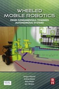
Two examples of commercially available systems in rehabilitation of walking are e-go from THERA-Trainer [38] and Andago from Hocoma [39], which are shown in Fig. 7.15.
In the following some more insight will be illustrated on the THERA-Trainer e-go and on its extended functionality version (Hoist project) that was researched by Bošnak and Škrjanc [37].
7.6.2 Setup
The moving platform THERA-Trainer e-go is meant for rehabilitation of walking in clinical use. The platform consists of two motor-driven wheels using differential drive kinematics and four caster wheels for stability. The patient’s waist is fastened to the vertical frame and the latter is at the bottom attached to the wheeled platform using elastic joints with limited range of angular motion to prevent the patient from falling. The therapist can manually control the platform motion and the patient should follow. The main goals of the therapy are [38] improved walking quality and increased walking speed, increased walking distance, and improved gait safety.
The main idea behind the Hoist project ([37], Fig. 7.16) is to equip the platform with additional sensors and algorithms to obtain autonomous (platform moves autonomously and the patient follows) or semiautonomous motion (platform moves considering to patient’s intentions) of the platform and adapt rehabilitation strategies accordingly. The patient intentions are predicted by measuring the angle of the vertical frame according to the base platform. For additional safety and for localization and mapping (SLAM) a laser range scanner is also included.

7.6.3 Sensors
In the Hoist project DC motors that drive the wheels are equipped with incremental encoders in order to control the wheels’ speed and enable implementation of odometry.
It turns out that patient intentions can be estimated from the tilt of the two rods that offer support to the patient. In the particular case, the tilt of each of the two straits is measured with a three-axis accelerometer and a three-axis gyroscope. A Kalman filter is used in estimation of the tilt (i.e., estimation of the direction of the gravity vector with respect to the local coordinate frame of the sensor) from the data provided by the accelerometer and gyroscope. Based on the measurement of the tilt of the two rods the displacement of the patient from the mobile robot center and also the orientation of the patient’s pelvis (around the vertical axis) with respect to the robot’s base can be determined. The mobile platform is equipped with an additional tilt sensor on the mobile robot base to enable estimation of the stait tilt with respect to the mobile robot base, which enables the use of the platform even on the inclined surface (Fig. 7.16).
To provide safe motion without collisions a laser range scanner is used and additional four bumpers to detect collisions (Fig. 7.16). A laser range scanner is also used for localization and mapping.
7.6.4 Localization and Mapping
Basic operation of the Hoist does not require localization and mapping. However, if the platform’s pose and environment map are known the patient’s walking routes can be preplanned and the therapists can monitor patient progress. According to the therapy goals the therapists can prescribe different walking routes (in the map of the environment) that are the most suitable to a particular patient. Based on the recorded performance data of the patient the therapist can gradually increase or decrease the level of difficulty to achieve optimal therapy results.
Capability of localization and mapping is required to enable advanced control capabilities that can enhance rehabilitation therapy. The mobile platform can autonomously guide the patient between arbitrary goals in the environment. It can notify the patient when he/she leaves the desired walking path prescribed by the therapist, or even help the patient to stay on the desired path whenever the patient needs some support.
7.6.5 Control
There are multiple levels of control that enable different modes of operation. At a low level, a control of the speed of each wheel based on the readings from the incremental encoder on the motor shaft is implemented. Since this mobile platform has differential drive, the reference tangential and angular speed of the mobile platform (or equivalently reference speeds of both wheels) can therefore be used as control actions in higher level control algorithms (cascade control).
One of the primary enhancements of the conventional robotic rehabilitation trainer is the capability of semiautonomous following the patient during the rehabilitation therapy. In this mode the patient controls the speed and turning of the platform. Based on the tilt measurements of both rods the control actions (reference wheel speeds) are calculated in a way that the mobile robot follows the patient. Determination of control signals is not straight-forward, since the control algorithm needs to be robust enough to filter out oscillations in tilt measurements that occur due to walking dynamics. In this control mode a negligible strain from the patient is required to move the platform, the patient determines the level of difficulty (speed) to his/her own capabilities, and the platform follows the patient seemingly. The therapist therefore no longer needs to drive the patient in the platform manually, but can only observe the patient and provide the patient with instructions.
The mobile platform in the Hoist project has been equipped with a laser range scanner that enables detection of obstacles in the range of 270 degrees up to a few meters in front of the mobile platform. The measured distances to the nearest obstacles in different directions are used implicitly in the control of the mobile platform in a way that collisions with obstacles are prevented. The control algorithm allows the patient to drive the mobile platform only in the directions that are free of obstacles. To enable soft touching (i.e., with zero velocity in the direction perpendicular to the obstacle) and also navigation through narrow passages (e.g., doors) the control actions are modified according to the estimated time to collide (based on predicted motion). In this way the patient can carry out the rehabilitation therapy safely alone without constant monitoring from the therapist.
Since a laser range scanner enables implementation of SLAM, this enables the design of some more advanced control strategies that can further enhance the rehabilitation therapy. Therefore a path following and trajectory tracking control algorithms can be implemented. In a particular case different control modes have been considered. The mobile platform is capable of autonomously driving the patient along the desired path. In this mode the patient has no control over the mobile platform and needs to follow it. Although if the mobile platform detects the patient is not capable of following (based on tilt measurements), the speed is reduced or the task is terminated. In another control mode, the patient should walk along the path designed by the therapist and the mobile platform is only following the patient and prevents too large deviations from the desired path. In yet another control mode, the mobile platform can also provide the patient some assistance in following the path whenever it detects (from the measurement of the pose error and straits tilt) help is required. Therefore, new rehabilitation therapy approaches can be achieved that were previously not possible.
7.6.6 Path Planning
In order to enable autonomous navigation of the mobile platform between arbitrary goals in the environment the path planning problem needed to be addressed. For this purpose the A⋆ algorithm is used where the footprint of the mobile platform shape is taken into account. Due to the particular shape of the mobile platform, the assumption of a round robot for the purpose of path planning simplification is not preferred. Since the smallest circle around the axis of rotation that encircles the whole mobile platform is much larger than the actual outer convex envelope of the robot, the simplified path planning algorithm would fail to find the path between narrow (and also between relatively wide) passages. To overcome this problem the boundary of the mobile platform is approximated with a rectangle that is used during the path planning.
The result of A⋆ path planning is a sequence of points (states) that represent the feasible path that connect the start pose with the goal pose. To enable smooth trajectory tracking the path needs to be smoothed. For this purpose a smooth spline of parametric curves is fitted to the obtained sequence of path points. In path planning not only is it important to design the shape of the path, but also to design an appropriate path velocity and acceleration profile. The goal of path planning is therefore to also take into account some velocity and acceleration constraints that are imposed by the particular patient’s capabilities. Path planning algorithms can therefore also enable the therapist to customize the rehabilitation therapy in order to achieve optimum results.