Electrochemical Aspects of Corrosion-Control Coatings
L.H. Hihara Hawaii Corrosion Laboratory, Department of Mechanical Engineering, University of Hawaii at Manoa, Honolulu, Hawaii, USA
Abstract
Corrosion of metals is an electrochemical process and is affected by moisture content, the chemical environment, and the electrochemical state of the metal. How the properties of a coating or coating system affect the above parameters governs the effectiveness of the coating in suppressing corrosion. Fundamental electrochemical aspects of corrosion are discussed, as well how coating properties (i.e., barrier characteristics and electrical resistivity, chemical and electrochemical) affect the corrosion behavior of the substrate metal. Barrier protection, corrosion inhibition, and cathodic protection as they relate to coatings are discussed.
1.1 Introduction
In nature, almost all metals are found in their thermodynamically stable states which are ores that are comprised primarily of oxides, sulfides, and halides.1 Energy must be expended to extract the elemental metals from the ores. Hence, as soon as the elemental metals are extracted from their ores, they have a propensity to revert back to their thermodynamically stable compounds. In most cases, metals will form oxides when exposed to moisture. If the oxide is porous or does not have good adhesion to the substrate metal, the metal will actively corrode. If the oxide forms a compact impervious layer and has good adhesion, the metal will passivate, resulting in excellent corrosion resistance. In environments that contain aggressive ions, however, the passive film can breakdown, resulting in localized corrosion and very high corrosion rates. Hence, coatings are very frequently needed to suppress corrosion in metals that do not naturally form protective passive films or for aggressive environments that can break down passivity.
1.2 Corrosion
For a metal to corrode by aqueous corrosion, water molecules must be present. The metal, however, need not be fully immersed because water can condense on a surface due to temperature fluctuations, even if the relative humidity is lower than 100% (e.g., condensation on cold surface on a warm, humid day), or due to hygroscopic impurities such as airborne salts.2
1.2.1 Thermodynamics
Aqueous corrosion is an electrochemical process involving anodic (or oxidation) and cathodic (or reduction) reactions. Dissolution of a metal M, which is an anodic reaction, is represented by the half-cell reaction
The electrons of the anodic reaction must be consumed by a cathodic reaction for corrosion to proceed. Two predominant cathodic reactions in aqueous corrosion are oxygen reduction (Equations 1.2 and 1.3) and hydrogen evolution (Equations 1.4 and 1.5), respectively. Their half-cell reactions are represented as follows:
Oxygen reduction can only occur in aerated solutions, which contain dissolved oxygen molecules. Hydrogen evolution can occur in both deaerated and aerated solutions.
For example, in an aerated basic solution with oxygen reduction as the cathodic reaction, the overall corrosion reaction can be represented as

In a deaerated acidic solution, the overall corrosion reaction of a metal can be represented as

where hydrogen evolution is the cathodic reaction.
For corrosion to occur, however, the cell potential, Ecell, of the overall corrosion reaction must be positive, which corresponds to a decrease in Gibb’s Free energy. Ecell is the difference in the equilibrium potential of the cathodic half-cell reaction and the anodic half-cell reaction. For example, for the corrosion of a metal in an acidic solution with hydrogen evolution as the cathodic reaction (Equation 1.4), Ecell would be calculated as follows:
where the equilibrium potential of the half-cell reactions (i.e., ![]() and
and ![]() ) can be determined using the Nernst equation:
) can be determined using the Nernst equation:
where E° is the standard potential, R is the universal gas constant, T is the absolute temperature, n is the number of electrons transferred in the half-cell reaction, F is Faraday’s constant (or charge on one mole of electrons), and areactants and aproducts are the activities for the reactants and products, respectively. The value of Ecell only indicates if the reaction is thermodynamically possible or impossible, and therefore, the study of kinetics is required to obtain the rates of the corrosion reaction.
1.2.2 Kinetics
In the study of corrosion, polarization diagrams3 are used to determine the rates of metal dissolution, oxygen reduction, and hydrogen evolution. The thermodynamic driving force for the electrochemical reaction is measured in potential, E, on the vertical axis of the polarization diagram. The kinetics of the electrochemical reaction are measured in current, I, on the horizontal axis of the polarization diagram. Notice that the anodic (Equation 1.1) and cathodic reactions (Equations 1.2–1.5) involve the transfer of electrons, and, therefore, their rates are proportional to the current. Based on Faraday’s law, the moles, N, of species reacted is related to the current, I:

where t is the duration of the current I, F is Faraday’s constant (or charge on one mole of electrons), and n is the moles of electrons participating in the reaction:
Anodic reactions generate anodic currents, IA, and cathodic reactions generate cathodic currents, IC. The currents are often normalized with respect to the surface area, A, of the electrode:


Depending on the metal and environment, metals may have active, passive, or active-passive electrochemical behavior. Active metals and alloys do not form protective passive films and show increasing anodic currents (Figure 1.1) as the potential is increased above the open-circuit or corrosion potential (Ecorr). Passive metals form protective passive films and have very low dissolution currents (Figure 1.2) at potentials more positive than Ecorr. Active-passive metals (e.g., Cr, Ni)4 generally show active, passive, and transpassive regimes on the anodic polarization diagram (Figure 1.3). In the active regime from Ecorr to the primary passive potential (Epp), the metal dissolution rate increases as the potential increases. In the passive regime, a protective oxide passive film forms on the metal at potentials greater than Epp causing the current to dramatically decrease. In the transpassive regime at more noble potentials, the anodic current again increases either due to passive-film break down leading to metal dissolution or the evolution of oxygen.2


Aggressive anions, commonly from the halide group (e.g., Br−, Cl−), can prevent passivation, resulting in localized corrosion or pitting of the metal surface. Pitting commences when the electrode potential exceeds the critical value known as the pitting potential (Epit),2 which also decreases with increasing aggressive-anion concentration (Figure 1.4).5

In corrosion, the predominant cathodic reactions are proton reduction and oxygen reduction. In deaerated environments, only the proton reduction occurs; but in aerated environments, both proton and oxygen reduction can occur. Hence, on a polarization diagram, only proton reduction will be seen in deaerated environments, while both proton and oxygen reduction may be seen in aerated environments (Figure 1.5). The current of the oxygen-reduction curve will saturate when the rate at which oxygen molecules reach the cathodic sites is limited by diffusion. The diffusion-limited current can increase with higher oxygen concentrations and thinning of the diffusion layer (e.g., by agitation of the electrolyte in bulk solutions or evaporation for thin electrolyte films).

When corrosion occurs, the amount of electrons generated by metal dissolution is equal to that consumed by the cathodic reactions to conserve charge. Hence, the corroding material assumes the corrosion potential, Ecorr, where the anodic, iA, and cathodic, iC, current densities have the same magnitude, called the corrosion current density, icorr (Figure 1.6).

1.3 Coatings
Corrosion-resistant coatings and coating systems generally provide one or more of the following characteristics to protect the metal substrate: (i) an impervious barrier to moisture and corrosive species, (ii) corrosion inhibition utilizing corrosion inhibitors, and (iii) cathodic protection. Single-layered, stand-alone coatings or more complex multilayered coating systems can be used. A multilayered coating system may be comprised of a pretreated surface layer and primer layers to enhance adhesion and provide corrosion inhibition to the substrate metal, undercoat layers to enhance durability, and topcoat layers for aesthetics and added environmental resistance (Figure 1.7).

1.3.1 Barrier coatings
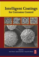
Barrier coatings ideally protect the substrate metal by providing an impervious barrier to moisture and corrosive species. Corrosion cannot initiate if moisture is not present; hence, the substrate metal will be free of corrosion if the barrier coating is intact, but will initiate from coating breaches in the presence of moisture and corrosive species. The electrical and electrochemical properties of the barrier coating can also affect the degree of corrosion that initiates at the breaches.
During corrosion, the total anodic current from all sources must equal the total cathodic current from all sources:
In the expression above, the currents can be written as a product of the current densities, i, and the corresponding areas, A:
The subscripts “A” and “C” are used to denote anodic and cathodic, respectively; the subscript “breach” refers to the exposed substrate region at coating breaches, and “coating” refers to the coating. Solving for iA,breach, which represents the dissolution rate of the substrate at coating breaches, gives

For barrier coatings which are not sacrificial, iA,coating is taken as zero:

Hence, the anodic dissolution of the substrate at the coating breach, iA,breach, is a function of the cathodic current density of the exposed substrate at the breach and the cathodic current density on the coating multiplied by the coating-to-breach area ratio. Coatings that are electrically conducting and that can support cathodic reactions such as oxygen reduction or hydrogen evolution can have large values of iC,coating. Given that the coating-to-breach area ratio is usually very large (i.e., > 100), the dissolution or corrosion at the coating breach, iA,breach, will be concentrated, leading to accelerated localized corrosion (Figure 1.8). Therefore, it is usually not recommended to use noble metals (e.g., copper, silver, gold) as barrier coatings to protect more active metals (e.g., aluminum, steel). It is likely that conductive polymer coatings could also have this effect; hence, barrier coatings that are electrically insulative or that do not support oxygen reduction or hydrogen evolution are likely to provide much more overall protection. In the limiting case where iC,coating is zero, the corrosion rate at exposed substrate regions at the coating breaches will be equal to the normal corrosion rate of the bare substrate (Figure 1.9):

Organic coatings such as epoxies, alkyds, acrylics, etc., are generally applied by spraying or brushing. These coatings are generally permeable to water molecules, absorb moisture, and maintain a concentration of water that is in equilibrium with moisture in the atmosphere. If the coating has good adhesion to the substrate, however, the water molecules remain within the molecular structure of the coating and do not accumulate at the coating-substrate interface.6 If the coating adhesion is poor due to either the inherent properties of the coating and substrate or the possibility of the substrate surface becoming contaminated—for example, by airborne salts—the water molecules in the coating could accumulate or condense at the coating-substrate interface forming blisters in the coating, which could lead to corrosion.6 Hence, cracks or breaches in organic coatings are not always necessary for moisture penetration to the substrate interface.
Inorganic coatings such as oxides, nitrides, carbides, and so on, are generally applied by chemical vapor deposition, sputtering, or evaporation, and require vacuum chambers. These coating are often inherently impervious to moisture, but they are brittle and can crack and spall. Other inorganic coatings can be grown directly on the substrate metal by chemical or electrochemical processes. Examples are anodized films on aluminum. These films can either be compact and impervious to moisture or porous depending on processing parameters.
To overcome some of the inadequacies of purely barrier coatings, corrosion inhibitors are often added to coating formulations to provide added corrosion protection.
1.3.2 Corrosion inhibitive coatings
Corrosion inhibitors are chemical species that are used to suppress the reaction rates of electrochemical processes to control corrosion. The inhibitors are usually used at low (e.g., parts per million) concentration levels. Anodic inhibitors suppress the anodic reaction rate, which is depicted by shifting the anodic polarization curve to the left (Figure 1.10) to lower current densities, resulting in lower icorr and an increase in Ecorr. Cathodic inhibitors suppress the cathodic reaction rate, shifting the cathodic polarization curve to the left (Figure 1.11) to lower current densities, resulting in lower icorr but a decrease in Ecorr. If anodic and cathodic inhibitors are used simultaneously or if an inhibitor suppresses both the anodic and cathodic reactions, both anodic and cathodic curves will be shifted to the left to lower currently densities, resulting in lower icorr and a possible increase or decrease in Ecorr that will be dependent on the extent of the shift in the anodic and cathodic curves (Figure 1.12).


Inhibitors are often included in surface pretreatments and primers in coating systems. A very effective inhibitor that has been historically used in many applications is hexavalent chromium. However, due to the carcinogenic properties of hexavalent chromium under some conditions, its use is being phased out, which has led to many research and development activities to find or develop less toxic replacements.
1.3.3 Cathodic-protection coatings
In these coatings, the protection mechanism operates on the principle of cathodic protection. The coatings can be either metallic or semiconductive. Metallic coatings have to be electrochemically more active than the substrate metal that is to be protected, and semiconductive coatings have to be n-type semiconductors. The metallic coatings are sacrificial and corrode preferentially to protect the substrate, and the n-type semiconductors operate on the photo-electrochemical effect.
1.3.3.1 Sacrificial metallic coatings
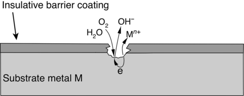
These coatings are consumed or sacrificed to protect the substrate metal. A classic example is galvanized steel where mild steel is protected with a layer of zinc. Typically, with galvanized steels, the zinc coating suppresses the potential of the mild steel at coating breaches and therefore prevents the steel substrate from corroding until a significant fraction of the zinc coating is consumed (Figure 1.13). With the use of polarization diagrams, this process can be described as follows: When a metal M naturally corrodes, it settles at its corrosion potential, Ecorr,M, and corrodes at a rate of icorr,M (Figure 1.14). If the metal M is then electrically connected to a more active metal A (i.e., metal A has a more negative Ecorr than that of metal M) and both are immersed in the same electrolyte, the potential of metal M and that of the more active metal A will equilibrate to the galvanic potential, Egalv. In addition, the corrosion rate of metal M will be suppressed to idiss,M (coup to A) (Figure 1.14) or stop completely if Egalv drops below the equilibrium potential for metal M, ![]() (Figure 1.14). The corrosion rate of the more active metal A will increase from icorr,A (when it is uncoupled) to igalv when it is coupled to the more noble metal M (Figure 1.14). Hence, metal A will be “sacrificed” to protect metal M.
(Figure 1.14). The corrosion rate of the more active metal A will increase from icorr,A (when it is uncoupled) to igalv when it is coupled to the more noble metal M (Figure 1.14). Hence, metal A will be “sacrificed” to protect metal M.

For cathodic-protection coatings, the sacrificial, active metal used in the coating has to be in electrical contact with the metal substrate that is to be protected. Contact to the substrate can be achieved, for example, by coating the active metal onto the substrate by hot-dipping in a bath of the molten metal, flame spraying the metal, or electrochemically plating the metal from an aqueous bath. Alternatively, particles of the active metal can be incorporated into a binder and then sprayed onto the substrate. The binder can be organic (e.g., chlorinated rubbers, vinyls, epoxies) or inorganic (e.g., silicates).6 The loading of the active metal has to be sufficiently high (e.g., in the case of Zn coatings, 90-95 wt.% of the dry coating6), such that the coating is electrically conductive to allow electrons generated from the corrosion of the sacrificial active metal to migrate to the substrate to induce cathodic protection. The characteristics of the binder can also have secondary effects. For example, when zinc particles are incorporated into inorganic silicate binders, the zinc corrosion products plug defects in the coating as the zinc particles are consumed, making the coating denser.6 This plugging mechanism is not generally achieved with organic binders. Hence, zinc coatings with inorganic silicate binders may be effective for decades in marine environments compared to months-to-years for zinc in organic binders.
1.3.3.2 N-type semiconductor coatings
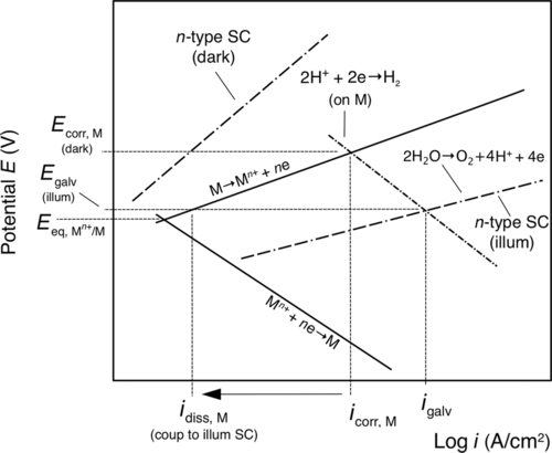
Cathodic protection can also be achieved by using coatings that are or contain n-type semiconductors. Cathodic protection is achieved, however, from a photo-electrochemical effect and not by the sacrificial corrosion of the coating. An n-type semiconductor is photo-anodic and under illumination promotes photo-oxidation reactions, such as the oxidation of water. Hence, in the presence of moisture and under illumination, photo-generated electrons from an n-type semiconductor coating could polarize the substrate to more negative potentials to induce cathodic protection.7 Under illumination, Ecorr shifts from Ecorr, M (dark) to Egalv (illum), and the dissolution of the substrate decreases from icorr,M to idiss,M (coup to illum SC) (Figure 1.15). Due to the requirement of illumination, cathodic protection would only be achieved during daylight periods.
1.3.4 Coating systems
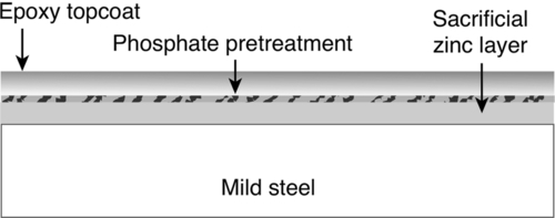
When significant corrosion protection is required, a single layer of coating may not be sufficient, and a more robust coating system may be needed that employs surface pretreatments, primers, undercoats, and topcoats. For example, mild steel can be coated with zinc, pretreated with zinc phosphate, and then top-coated with epoxy (Figure 1.16). With this coating system, the sacrificial zinc layer will cathodically protect the mild steel by galvanic action even if the zinc layer is breached (Figure 1.13). The zinc-phosphate pretreatment increases the adhesion of the epoxy topcoat, which prolongs the life of the zinc coating by suppressing the normal corrosion of zinc. Hence, the zinc will be consumed only when it is needed to protect the mild steel substrate.
When using coating systems, however, it is important that there is compatibility between the different layers, and that they work together or in synergy to enhance overall corrosion protection. Using the wrong combination of coating materials can lead to premature failure. For example, the solvents used in one coating layer could compromise the integrity of an adjacent coating layer, resulting in loss of adhesion or cohesion, etc.6 Hence, the compatibility and performance of using multiple coating layers should be tested and verified prior to implementation.
1.4 Conclusions
Most metals require the application of a protective coating or coating system to provide an acceptable level of corrosion protection for an intended application. As corrosion of metals is an electrochemical process, it is controlled by moisture content, the chemical environment, and the electrochemical state of the metal. Hence, corrosion can be attenuated by using coatings that effectively control the above parameters. Coating properties such as adhesion, cohesion, imperviousness to moisture, electrical resistivity, catalytic properties for oxygen reduction and hydrogen evolution, corrosion inhibition, and electrochemical potential are all important in the control of corrosion, and how these are controlled or tailored in a coating or coating system will determine the level of corrosion protection achieved.