Low Temperature Coating Deriving from Metal-Organic Precursors
An Economical and Environmentally Benign Approach
Jyoti Prakash*; B.M. Tripathi*; Sunil Kumar Ghosh† * Powder Metallurgy Division, Bhabha Atomic Research Centre, Trombay, Mumbai, India
† Bio Organic Division, Bhabha Atomic Research Centre, Trombay, Mumbai, India
E-mail: [email protected]
Abstract
Generally, protective layer coatings, usually comprised of refractory materials, are used to protect substrate materials in oxidative/corrosive environments. The refractory materials used for coating must possess suitable properties such as high melting point, good thermal and chemical stability, and, in particular, the lowest thermal expansion coefficient mismatch with the substrate to avoid cracks and spall formation during the heating process. Several coating methods are available to deposit such materials in bulk; however, only few of them are cost effective as well as environmental friendly methods. Due to the serious concern over economy as well as environmental pollution, the economical and environmentally safer coating methods are gaining an ever increasing importance now-a-days over the conventional methods. The chemical vapor deposition (CVD) method of coating based on organometallic compounds as precursor has the potential to address economy- and pollution-related issues to a great extent. In addition, the use of organometallic precursors in the CVD process has the advantage of producing high-quality protective coatings without degrading the substrates. In this chapter, different variants of the CVD process, in which organometallic precursors are used for coating, are discussed in detail. The economical synthesis routes of some of the technologically important organometallic precursors and their growth mechanisms are also discussed.
4.1 Introduction
The performance of composites with metal, intermetallic, or ceramic matrices in many cases depends on the development of suitable coatings to protect against environmental degradation. For example, promising carbon composites undergo damage when thermally fatigued in oxidizing atmospheres.1,2 Many ceramic matrix composites (CMCs) lose a significant fraction of their room temperature tensile properties after preexposure in air at 1000 °C,3 and some nonoxide-reinforced oxide matrix composites that are thermochemically compatible in an inert environment form intermediate compounds when exposed to oxygen.4 Silicon carbide (SiC) and silicon nitride (Si3N4) ceramics and composites generally display excellent oxidation resistance but corrode severely in the presence of alkali compounds5,6 and therefore require protective coatings for use in industrial stack gas environments.7–9 Protective coatings may provide solutions to these problems if the integrity of the coating can be maintained throughout the projected service life of the component. Among the several key issues that must be considered when selecting coating materials are: (1) the coating must possess the ability to resist reaction with aggressive environments, as well as low oxygen permeability to limit the transport of oxygen, (2) the coefficient of thermal expansion (CTE) of the coating should be close to that of the substrate material in order to prevent delamination or cracking due to the stress caused by CTE mismatch, (3) the coating must maintain a stable phase under thermal exposure. Phase transformation typically accompanies a volumetric change, disrupting integrity of the coating, and (4) the coating must be chemically compatible with the substrate to avoid detrimental chemical interaction.
In the past few years, ceramic coatings have received considerable attention for a variety of reasons, including economics (substitution of expensive alloys by cheaper alternatives, extension of service life of alloys), material protection from wear, corrosion, and erosion, and improvement and development of new material properties.10–12 Ceramic coatings can be useful in a wide range of applications, such as thermal barriers for gas turbine blades and vanes; hot section parts of diesel engines; materials where wear, corrosion, and oxidation resistance are necessary; electrical insulation in electronic circuit substrates; and nuclear technology and medical applications.13–17
There are a number of factors to be considered when developing a coating process for an industrial application. These include capital investment, ease of manufacturing, coating performance, and environmental issues. Although a large number of coating techniques such as electrochemical plating,18 conversion coatings,19,20 anodizing,19 and polymer plating sol-gel coating;21,22 or plasma polymerization,23 chemical vapor deposition (CVD),24 physical vapor deposition (PVD),25 and so on are available for protecting materials, the widespread use of materials in the industry is still deterred by the lack of appropriate protective coatings that can withstand harsh service conditions. Therefore, a great deal of research is aimed at developing better, simpler, cheaper coating technologies so we can take advantage of the lower weight and excellent mechanical properties of this material. CVD is the most frequently used technique to deposit thick ceramic coatings (e.g., SiC, TiC, B4C, TiN, BN, Si3N4, TiB2, MoSi, and Al2O3) to protect engineering components against chemical diffusion, wear, friction, oxidation, and corrosion.26 The cost of CVD for the protective coatings market is generally lower than the functional thin films for the semiconductor industry as it involves coating a large volume of engineering components. Other competing deposition methods for protective coatings are plasma spraying27 and PVD. However, plasma spraying tends to produce a splatlike structure with a high degree of porosity, microcracks, and surface roughness. A thicker coating is required to provide adequate protection against wear and corrosion, and extensive grinding and polishing postdeposition is required to obtain a smoother surface. Moreover, the splatlike structure is mechanically not as robust as the equiaxed/columnar structure deposited using the CVD and PVD techniques. The PVD method is a line-of-sight process. Therefore, in the PVD process, use of multiple targets and a rotating substrate is often required to improve uniformity of the coating on complex shape components. However, CVD does not have such limitations. In the CVD process of ceramic coating a high deposition temperature is usually required to ensure good adhesion of the thick coating on the substrate as compared to lower deposition temperatures in CVD of thin films. Good coating adhesion is essential for thermal, chemical (corrosion, diffusion resistance), and/or mechanical (e.g., wear, abrasion resistance) properties. Therefore, this requirement limits the use of CVD for applications where the substrate or engineering components are susceptible to high temperatures. For example, the deposition of thick, hard, and wear-resistant coatings onto high-speed cutting tool steels using thermally activated CVD is less suitable because tool steel has a low austenising temperature (450-550 °C). The CVD deposition of protective coatings such as TiC and TiN would require high temperatures (> 1000 °C), which is above the tempering temperature of most steels.28 This leads to softening of the steel substrate, and therefore subsequent heat treatment is required for rehardening, which may cause deformation, change of substrate dimensions, and increase in the cost of production. However, there are other variants of CVD, such as plasma-enhanced CVD (PECVD) and metal-organic CVD (MOCVD), which can lower the deposition temperatures and produce high-quality ceramic protective coatings without degrading the tool steel substrates; but their cost of production is still relatively high compared to the other coating techniques. Many such limitations of CVD coating can be suitably addressed to a great extent by replacing conventional inorganic precursors with metal-organic precursors in CVD coating. In addition, using metal-organic precursors in CVD is economical and environmentally benign. The present chapter covers different variants of coating using metal-organic precursors as well as relatively cheaper synthesis routes for some of the metal-organic precursors that can be used for CVD coating.
4.2 Chemical Vapor Deposition: MOCVD Variant Techniques
CVD of films and coatings involves the chemical reactions of gaseous reactants on or near the vicinity of a heated substrate surface. This atomistic deposition method can provide very pure materials with structural control at an atomic or nanometer scale. Moreover, it can produce single-layer, multilayer, composite, nanostructured, and functionally graded coating materials with well-controlled dimensions and unique structures at low processing temperatures. Furthermore, the unique feature of CVD in contrast to other deposition techniques such as the non-line-of-sight-deposition process has allowed coating of complex shape engineering components and the fabrication of nano-devices, carbon-carbon (C-C) composites, CMCs, and free-standing shape components. The versatility of CVD had led to rapid growth, and it has become one of the main processing methods for the deposition of thin films and coatings for a wide range of applications including semiconductors (e.g., Si, Ge, Si1 − xGex, III-V, II-VI) for microelectronics, optoelectronics, energy conversion devices; dielectrics (e.g., SiO2, AlN, Si3N4) for microelectronics; refractory ceramic materials (e.g., SiC, TiN, TiB2, Al2O3, BN, MoSi2, ZrO2) used for hard coatings, protection against corrosion, oxidation, or as diffusion barriers; metallic films (e.g., W, Mo, Al, Au, Cu, Pt) for microelectronics and for protective coatings; fiber production (e.g., B and SiC monofilament fibers) and fiber coating.24
The conventional CVD method, so-called thermal-activated CVD (TACVD),29 uses thermal energy to activate the chemical reactions. However, the CVD reactions can also be initiated using different energy sources. This has given rise to other variants of CVD methods such as PECVD29 and photo-assisted CVD (PACVD),30 which use plasma and light, respectively, to activate the chemical reactions. Atomic layer epitaxy (ALE)31 is a special mode of CVD where a “monatomic layer” can be grown in sequence by sequentially saturating surface reactions. Such CVD variants are useful for the controlled growth of epitaxial films and the fabrication of tailored molecular structures. Flame-assisted vapor deposition (FAVD)32 uses a flame source to initiate the chemical reaction and/or heating of the substrate. Electrochemical vapor deposition (EVD) is another variant of CVD that is tailored for the deposition of dense films onto porous substrates. Chemical vapor infiltration (CVI)33 is a form a CVD that has been adapted for the deposition of a dense ceramic matrix during the fabrication of ceramic fiber-reinforced CMCs. Other CVD variants such as pulsed injection CVD34 and aerosol-assisted CVD35 use special precursor generation and delivery systems unlike conventional CVD.
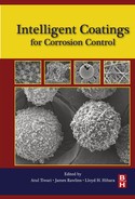
MOCVD36 is a variant of CVD, which has been classified according to the use of metal-organic compounds as precursors. Use of metal-organic precursors in MOCVD has several advantages, such as lower deposition temperature, safe operation, and cost effectiveness. Metal-organic compounds, also known as “metalorganics,” contain metal atoms bonded to some organic radicals. The compounds having one or more direct metal-carbon covalent bonds are called “organometallics.” Metalorganics as well as organometallics both can be used as precursors in MOCVD. Use of organometallic precursors has led to the rename of the deposition process as organometallic CVD (OMCVD) to reflect more precisely the choice of precursors used. In conventional OMCVD, the precursor is vaporized at low temperature, under reduced pressure condition and subsequently, metal film is deposited on a substrate surface at higher temperature by adsorption and thermal decomposition of the precursor. The various parameters that control this deposition technique are as following: (1) convection of the gaseous reagents, (2) diffusion of the reagents toward the substrate, (3) adsorption of the reagents onto the substrate, (4) chemical reaction of the adsorbed species producing nuclei and further reaction to give a metal film, (5) desorption of the gas products of the reaction, (6) diffusion of these products through the boundary layer, and (7) gas evacuation of the system (Figure 4.1).

The reader must keep in mind that in all deposition techniques described in this chapter, the important factors which determines the system is surface limited or transport limited are temperature, flow rate, pressure, reactor and substrate geometry. All these parameters are discussed elsewhere.10 Diffusions at the boundary layer are a complex phenomenon, and results cannot be applied directly from one system to another. The choice of a CVD method among all those described will be made regarding specifications of the deposit in terms of topology, purity, physical properties, process speed, and cost. Different variants of CVD which can use metal-organic precursors are described in detail in the subsequent sections.
4.2.1 Laser-induced chemical vapor deposition
In this technique, decomposition of precursor is induced with a laser beam (Figure 4.2).37,38 Laser-induced chemical vapor deposition (LCVD) has the advantages of better control of the decomposition mechanism compared to the traditional method and being able to function on a substrate-limited surface. This method allows the deposition in confined zones and at low substrate temperature. The process can be carried out with substrates that do not have high thermal conductivity, and the deposit growth kinetics is often faster than those observed with traditional OMCVD. In LCVD, it is also possible to work at higher precursor pressure than in traditional CVD because the growth kinetics here are being limited by gas-phase decomposition. Nevertheless, for most of the applications considered currently—repair of circuits, manufacture of prototypes, and so on—the writing speed remain slow (several ms− 1 depending on conditions). Deposit resistivity can be optimized toward deposition rate and laser power. Optimum required deposition rate is neither too slow nor too fast and laser power neither too weak nor too strong. Partial pressure of precursor seems to be the critical factor, allowing an increase in deposition rate without loss in the overall deposit quality. To obtain a film with few impurities, the laser must decoordinate all the precursor ligands, avoiding the incorporation of carbon and other elements into the film. The growth rate depends on the wavelength of light used and on the laser power. Photolysis can occur in several stages with quantum yields also dependent on the laser wavelength. Another phenomenon can occur when overheating of the deposit by the laser leads to the precursor desorption.39 When the laser induces excess heating of the substrate, the deposition cannot be considered pure LCVD, the precursor decomposition becoming primarily thermal and no longer photolytic.

4.2.2 UV-induced chemical vapor deposition
The OMCVD can also be carried out under the irradiation of a UV lamp, which can improve the process of nucleation while lowering the operational deposition temperature (Figure 4.3). In the case of UV-induced chemical vapor deposition (UVCVD) the deposition can be performed in two modes.40,41 The first, consisting of depositing the precursor on the substrate then irradiation; the second, depositing the metal directly by adsorption, followed by decomposition of the precursor by irradiation of the substrate. In both cases the deposition mechanism has been different and it affects the final coating morphology.

4.2.3 Plasma-enhanced CVD
PECVD is also known as glow discharge CVD (Figure 4.4). It uses electron energy (plasma) as the activation method to enable deposition to occur at a low temperature and at a reasonable rate. Supplying electrical power at a sufficiently high voltage to a gas at reduced pressures (< 1.3 kPa) results in the breaking down of the gas and generates a glow discharge plasma consisting of electrons, ions, and electronically excited species. The vapor reactants are ionized and dissociated by electron impact, and hence generated, chemically active ions and radicals that undergo heterogeneous chemical reaction at or near the heated substrate surface and deposit a thin film. The temperature of electron can be in the order of 20,000 °C or higher, while the temperature of the vapor reactants may remain near room temperature, depending on the pressure at which the discharge is operated. The chemical reactions that occur during the glow discharges are complex and can be categorized into homogeneous gas phase collisions and heterogeneous surface interactions. Bell42 has studied the ways to generate reactive free radicals and ions through the homogeneous gas phase collisions of electrons with vapor reactants and proposed generic examples of electron impact reactions and the rate of reactions. Inelastic collisions between heavy particles during the homogeneous impact reaction have also been considered. Catherine43 has considered the overall complexity of the plasma process and the growth kinetics during the PECVD of films. This includes the influence of parameters to generate the plasma and the characteristics of such a plasma (e.g., electron ion densities and fluxes, residence time, etc.), which influence the ion energy and substrate temperature. Unlike thermally activated CVD, there is limited available fundamental information about the PECVD process. Hence, it is difficult to establish the relationship between the processing parameters and properties of the films because of the complexity of the PECVD reactions. Therefore, PECVD has the advantage of low temperature depositions where it cannot be met by thermally activated CVD.

4.2.4 Electron beam chemical vapor deposition
Electron beam chemical vapor deposition (EBCVD) is a technology that uses an electron beam to provide localized deposition for nano-scale structures or device fabrication (Figure 4.5). In EBCVD, primary electrons from the beam impact a substrate, causing secondary electrons to be emitted. These secondary electrons play a prominent role in dissociating adsorbed reagent molecules to form a deposit on the substrate and volatiles that are then evacuated from the chamber. The deposition process depends on many factors, including the precursor and the electron beam properties. If the electron beam is not moved relative to the substrate, a dot is grown. A fiber is grown if the growth time is increased. If the beam is moved, lines or other structures can be deposited as in rapid prototyping. High aspect ratio structures can be deposited as supertips on atomic force microscope tips to improve resolution. The resolution of the structures obtained (20 nm for a beam of 30 kV and 7 nm for 200 kV) are better than those obtained with LCVD (10-100 μm) or with ions beams (100 nm). Although deposits resulting from the application of EBCVD contain a lot of carbon,44 the EBCVD method offers advantages over LACVD: leaving fewer impurities in the deposit and degrading the substrate less.45 A posttreatment consisting of a heating step in the presence of oxygen decreases the level of impurities. The deposit may then suffer from a volume reduction due to carbon impurity elimination.
4.2.5 Fluidized bed chemical vapor deposition
Fluidized bed chemical vapor deposition (FBCVD) is one of the most efficient techniques to functionalize, to deposit on, or to coat each individual particle of a powder from gaseous species (Figure 4.6).46 FBCVD combines two processes. One is the deposition itself, and the other aims in suspending the particles in the deposition zone, most often by flowing a gas upwards through the powder, and in bringing heat to the powder.47 In contrast to CVD on flat surfaces that often operates in a surface kinetics limited regime, FBCVD is generally transport limited. This is due to the extremely high available growth surface to heated volume ratios (S/V) in the deposition area. Consequently, gaseous precursors are very often totally consumed a few centimeters after their entrance into the fluidized bed reactor, but the high degree of gas solid mixing compensates for this discrepancy and ensures isothermal conditions and uniform deposition.

4.2.6 Atomic layer deposition (ALD)
ALE31 can be considered a special mode of CVD (Figure 4.7). It is a surface deposition process that can be used for the controlled growth of epitaxial films and the fabrication of tailored molecular structures on the surfaces of solid substrates. “Monatomic layers” can be grown in sequence, which is a characteristic feature of ALE. Therefore, the desired coating thickness can be produced simply by counting the number of reaction sequences in the process. The surface reconstruction of the monolayer formed in the reaction sequence will influence the saturation mechanism and the saturation density of the precursor. The ALE reaction sequences are normally performed in an “effective overdosing” condition to ensure a complete saturation of the surface reaction to form the monoatomic layer. Furthermore, such “effective overdosing” condition also provides good conformal coverage that allows uniform coatings onto complex shaped substrates. The sequencing in ALE also eliminates the gas phase reactions and enables a wider choice of reactants (e.g., halides, metalorganics, elemental metal, etc.). The ALE process has the potential to be scaled up for the deposition of high-quality thin films with excellent uniformity and reproducibility onto large area substrate.48,49 Layer-by-layer deposition processes have been tested with platinum precursors. Precursors, air or oxygen, and inert gases are introduced to the reactor in alternate pulses onto the hot substrate. A single atomic layer is formed through an autolimited growth mechanism. The complex partially decomposes by consuming all the available oxygen adsorbed on the precursor surface and the following oxygen pulse will finish the decomposition. Decomposition products are CO2, water, and hydrocarbon residues if present in the starting precursor. Film growth is slow when the deposition starts because of the nucleation step. The films obtained are much uniformed and have a rough surface and highly oriented grains. Adhesion of the films on these substrates is modest, but the amount of all impurities is low and decreases as the air pulse time increases. The decomposition limits its application and makes it also unsuitable for use in ALD conditions.

4.2.7 Focused ion-assisted chemical vapor deposition (IACVD)
Ion beams have been used for the local deposition in the OMCVD process.50 In ion-assisted deposition, the ion beam decomposes an adsorbed layer of an organometallic precursor. This decomposition generates metal atoms on the surface of the substrate; the organic fragments diffuse away and are exhausted from the system. Film composition will therefore depend on the efficiency of precursor dissociation as well as the efficiency of volatile by-product diffusion away from the sample surface (Figure 4.8). These two parameters both should depend on the relative arrival rates of Ga+ ions and of precursor molecules on the sample surface in case of Ga source. The effects of Ga+ ion and precursor fluxes on the platinum film composition and resistivity have been determined for platinum deposition from organoplatinum compounds. Results show that increasing precursor flux at constant ion flux increases Pt and C, but decreases Ga content of the film.51 Increasing ion-flux, at constant precursor flux, increases Pt content, while decreasing C content of the film. Resistivity neither depends on the film thickness nor on temperature, but was shown to follow C content; films with lower C content have lower resistivity.51

4.3 Organometallic Precursors: Economical Bulk Synthesis
In CVD, the solid phase is formed on a surface from a gas phase via one or several chemical reactions.21 A key issue is the generation of the gas phase, whose composition must be stable during the deposition run. Hence, the choice of the precursors as well as of the delivery scheme is of utmost importance. Since the precursors are usually liquid or solid at room temperature and atmospheric pressure, an evaporation unit is required. Generally, organometallic precursors are preferred rather than halides since they are usually volatile at a much lower temperature (≤ 300 °C). The organic groups used for synthesis of organometallic precursor compounds broadly belong to β-diketonates, carbonyl and phosphine, cyclopentadienyl, and olefin and allyl family (Figure 4.9). Most commonly used precursors such as tetramethyl-heptanedionate compounds (tmhd: C11H19O2), which are solid at room temperature, belong to the β-diketonates family. These precursors can be dissolved in an appropriate solvent, like monoglyme or octane. However, the β-diketonates exhibit a very poor thermal stability at their volatilization temperature. They tend to decompose before their complete evaporation, forming nonvolatile products. Thus, if they are evaporated in classical units such as a sublimator (for powders) or a bubbler (for liquids), a drift of the vapor pressure occurs upon prolonged heating, which in turn results in a drift of the final cationic composition. This issue became very clear for the deposition of compounds, which requires a stringent control of the stoichiometry. In addition, since the evaporation temperature has to be maintained below the decomposition temperature of the precursor, very low vapor pressures were obtained. These issues can be sorted out by using a suitable delivery system for liquid/solid precursors, a concept that is discussed in a later section. There have been several precursor synthesis routes, but few are selected here for different organometallic compound synthesis on the basis of economy and environment friendly routes. In the next section different organometallic compounds with their mostly used economic and environment friendly routes are discussed.

4.3.1 Organometallic precursors: oxide ceramics
4.3.1.1 Alumina precursors
Alumina (Al2O3) films are deposited by CVD to improve the performance of cemented carbide cutting tools, whereby in industry normally only the AICl3,/CO2/H2 reaction gas at temperatures around 1000 °C is used.52 Instead of halide reaction gases, organometallic precursors enable Al2O3 coating at relatively low temperatures. The different reaction systems that were investigated can be classified into two groups: (1) aluminum alkyl compounds such as trimethyl-Al and oxygen or oxygen donors, and (2) aluminum alkoxide compounds. A limiting factor for the MOCVD technique is the high temperature sensitivity of most precursors and the violent reaction with oxygen or water. Most experiments in the literature using Al and O reported deposition using Al organic precursors was carried out at temperatures below 800 °C.53
4.3.1.1.1 Synthesis of aluminum isopropoxide
This compound is commercially available. Industrially, it is prepared by the reaction between isopropyl alcohol and aluminum metal, or aluminum trichloride (reaction scheme 4.1 and 4.2):
Using aluminum metal, an older process uses a mercury catalyst (see below), whereas a more recent process does not.54 In the laboratory, a widely accepted method for preparing aluminum isopropoxide was published in 1936 by Young et al.55 Their procedure entails heating a mixture of 100 g of aluminum, 1200 mL of isopropyl alcohol, and 5 g of mercuric chloride at reflux. The process occurs via the formation of anamalgam of the aluminum. A catalytic amount of iodine is sometimes added to initiate the reaction, which can be quite vigorous. Young et al. achieved an 85-90% yield, after purification by distillation at 140-150 °C (5 mmHg).
4.3.1.1.2 Synthesis of Al-acetylacetonate
A general method of synthesis is to treat a metal salt with acetylacetone, acacH (reaction scheme 4.3):56
Addition of base assists the removal of a proton from acetylacetone and shifts the equilibrium in favor of the complex. Both oxygen centers bind to the metal to form a six-member chelate ring. In some cases the chelate effect is so strong that no added base is needed to form the complex. Some complexes are prepared by metathesis using Tlacac. In a typical synthesis route for Al-acetylacetonate (reaction scheme 4.4), ammoniacal solution of acetylacetone and aluminum sulfate, Al2(SO4)3.16H2O, solution were prepared. The ammoniacal solution of acetylacetone was added to the aluminum sulfate solution in small portions, with swirling. After complete addition of acetylacetone solution, the pH of solution was measured using blue litmus paper. If the solution was still acidic, ammonia was added by drops until it was just basic. It was left standing for 15 min and then filtered, washed with distilled water, and dried by suction. The product was transferred to a watch glass and air dried. A portion of the sample from cyclohexane was recrystallized. The resulting crystals were isolated by filtration, washed with a small volume of cold cyclohexane and dried in air.
One of the advantage of present synthesis route was the use of industrial alum Al2(SO4)3.16H2O as the starting material in order to give alternative uses of this important industrial by-product in the production of alumina. Al-acetylacetonate was used to deposit A2O3 coatings on different substrates in the temperature range of 400-600 °C at atmospheric pressure in air.57
4.3.1.2 Zirconia, silica, titania precursors
A very versatile technique used for coating zirconia, silica, and titania is by sol-gel method. In this chapter mostly precursors suitable for CVD technique have been discussed, so we will now briefly describe different sol-gel organometallic precursors for zirconia, silica, and titania. This method allows a good reproducibility of coating performances even though some problems have been evidenced due to complex shape substrate and thick film deposition. Moreover, in some cases, coating cracking induced by the thermal treatment performed at the end of deposition has been reported.58 Usually a thermal treatment at a temperature around 600 °C provides a good chemical homogeneity and good corrosion resistant features to substrates. Nevertheless, some promising results, in terms of corrosion resistance, have been obtained also at lower temperature (400 °C).59
In general terms, the sol-gel process involves three stages: (1) a partial hydrolysis of the metallorganic compound in order to produce reactive monomers, (2) a polycondensation of the reactive monomers, which forms oligomers of colloidal size (sol), (3) and finally an additional hydrolysis, which initiates and further promotes the polymerization and cross-linking of the precursor. The last step, gelation, will produce polymeric compounds of given morphology that upon pyrolysis yield oxide ceramics. The above reactions can be influenced by controlling parameters such as pH, nature, and composition of the solvent, temperature, reaction time, ratio of [RO]/[H2O] (RO is aloxy group attached to metal), and the type of the R group.60–62 The nature of the starting metallorganic material undoubtedly constitutes an important parameter which influences all the steps of the sol-gel process. We will not go in further detail of effect of all these parameters and will focus on the deposition chemistry from organosilicon compounds.
4.3.1.2.1 Titania precursors: sol-gel
Titanium alkoxides which after hydrolysis produce amorphous TiO2 are widely used for titania production in firm of coating/powder. There are two proposed flowsheets (I and II) for the production of low temperature TiO2.63,64 The results indicate that anatase is the product in the first case where the washed amorphous TiO2 after being dispersed in a basic aqueous solution is heated in an autoclave at 200-300 °C. In the second case a mixture of anatase and rutile is obtained following the 16 h calcinations of the thoroughly washed amorphous TiO2. These differences are believed to be due to different pathways through which hydrolysis and polycondensation take place. The overall reaction (reaction scheme 4.5) despite its simple appearance is more complex because of the possible polymeric form of the alkoxide precursor:
Polycondensation can produce Ti-O-Ti bridges (reaction scheme 4.6) which will be preferentially linear if the solutions are diluted.65 Several other forms can also be produced, O on the conditions and

structure of the alkoxy group, represented by the following general formula Ti3(x+ 1)O4x(OR)4(x+ 3).66 Their structures can be more complicated if the possible tetramer Ti(OC2H5)4(I) is polycondensed linearly.
Reaction Flow Sheet I:
Reaction Flow Sheet II:
4.3.1.2.2 Silica precursor: sol-gel
The most frequently used and studied precursors for silica are tetraethylorthosilicate (TEOS)67 and tetramethylorthosilicate (TMOS),68 and they have been shown to behave differently under similar conditions. This indicates the importance of the molecular structure in the process and the need for more research and studies of the structure/sol-gel relationship in which all the reaction parameters are involved.
Silicon alkoxides are usually used as precursors and their hydrolysis rate can be controlled easily as compared to other faster hydrolyzed derivatives, such as SiCl4 and Si(OCOCH3)4. Silicic acid and its acetate are also able to produce SiO2. The solvent will influence the physical characteristics of the final product, and in the case of methanol as the solvent, the porosity of the product will be lower than that produced from TEOS under similar conditions. Similarly, the bulk density increases with temperature and is higher when MeOH is used as solvent.
In the acid-catalyzed system the hydrolysis rate usually decreases with an increase of C atoms in the straight-chain alkoxy group because of an inductive effect, whereas the rate is lowered with increased branching of the alkoxy group of the organosilicon alkoxides due to steric reasons. The polycondensation being a nucleophilic reaction will be influenced by the same factors up to the point at which cross-linking takes place. Other phenomena, such as diffusion and collisions between polymeric chains, are increasingly involved and thus the kinetics are dependent on additional parameters. In general, the hydrolysis reaction is much faster than the condensation. Nevertheless, condensation starts as soon as an alkoxy group has been hydrolyzed and thus the final results of the sol-gel of the silicon alkoxides will be influenced by a combination of the above-mentioned factors. The gelation characteristics of gels produced from methoxy (TMOS), ethoxy (TEOS), and butoxy (TBOS) silicon alkoxides support the above theory. An increase of gelation time is observed when the same alkoxide is used in solvents of increasing molecular weight, for example, MeOH, EtOH, and PrOH. A similar increase is observed with increasing molecular weight of the alkoxide used.69
4.3.1.2.3 Zirconia precursor: sol-gel
Alkoxides are the main source of metallorganic precursors for the formation of zirconia. The most frequently used Zr alkoxides (propoxide and butoxide), being liquids, can be purified by distillation, as is commonly done for the Si and A1 precursors. The Zr gels derived from these precursors can have the weight-loss reaction completed at substantially lower temperatures.
Their hydrolysis pattern is different from those of aluminum and silicon alkoxides, and their tendency toward total hydrolysis is lower than that for the titanium analogues. Zirconium does not give a hydroxide but rather a white gelatinous hydrated oxide (ZrO2.xH2O) which upon pyrolysis becomes ZrO2. The hydrolysis of the alkoxides produces several polymeric forms of the zirconyl ion (ZrO2 +) which eventually will form ZrO2 according to the following reactions (reaction scheme 4.7 and 4.8):
Depending on the amount of H2O added during reaction scheme (4.7), some of the species can be formulated and their thermal decomposition can be represented by reaction (reaction scheme 4.9):
but, in reality the process produces a mixture of ZrO2 and Zr2O3(OR)2.70 Apart from these differences the reactions which take place during hydrolysis and polycondensation are influenced by the same parameters as before, that is, temperature, solvents, the alkoxide/H2O ratio, and the presence of foreign ions in the solution. A significant phenomenon which is related to the chemical behavior of zirconium and the hydratesoxides rather than hydroxides it forms, is the lack of influence that the alkoxide/H2O ratio has on the oxide content of the hydrolysis products. Usually, an increase of the hydrolysis H2O will increase the hydroxyl groups of the hydrolyzable alkoxide, and as a result the oxide content will increase. In the case of the zirconium alkoxides the oxide content is about 80% no matter if the hydrolysis takes place in an excess of H2O or by atmospheric moisture.
4.3.1.2.4 Zirconia, yttria, silica precursors: CVD precursors
Several yttrium, zirconium, and silicon complexes with acetylacetone, tetramethylheptanedione, hexafluoroacetylacetone, tetramethylethylenediamine, polyether, and amine as ligands were synthesized by adjusting the pH after mixing chlorides/alkoxides of corresponding metals with the corresponding ligand in ethanolic or aqueous solutions. Drake et al.71 have reported a simple and economical technique to synthesize the adduct complexes of metals using different ligands. Their synthesis for metal complex adducts formation was as follows:
First, this approach aims to coordinatively saturate the metal centers with the combined use of both a chelating chain type ligand, that is, glymes or amines, and a chelating metalated group, for example, a diketonate, functionalized alcohol, diolate, or acetate (A-R-BH, where A is generally a pendant b-chelating site, R is the hydrocarbon chain linker, and B-H is the predominate site of metalation).35 The general synthetic strategy is outlined as follows (reaction scheme 4.10):
This point is of importance and presumably gives rise to their exceptional stability in the atmosphere, since the chelating ligands are less readily hydrolyzed than would be monodentate alkoxides. Second, the application of multidentate ligands (L-L) has been previously shown to force oligomeric complexes into a more strictly molecular regime, generally reducing the possibility of interactions between monomeric units (although there will always be exceptions to this). Third, this technique of using a preformed metal β-diketonate (either anhydrous or a hydrate) leads to water-free products. Thus hard Lewis bases (either O- or N-based) can utilize the entropic advantages of the chelate effect and facilitate the preparation of anhydrous metal β-diketonates is a low cost route, for example, by the use of simple hydrated complexes prepared via metathesis in aqueous/alcohol media. This latter point has an importance if such materials are going to have real applications as either sol-gel or CVD precursors, where low-cost chemicals that may be manipulated on the open laboratory bench are an important objective.
There were several reports on the synthesis of Zr(tmhd)4, (thd)2Zr(OR)2, and Y(tmhd)3 and their diglyme, triglyme adducts.72–75 The kinetic data of evaporation for Zr(tmhd)4 and Y(tmhd)3 are reported in literature. Complete volatility and low temperature range of sublimation/vaporization below 250 °C for Zr(tmhd)4, Y(tmhd)3(H2O), and Y2(tmhd)6(triglyme) make these compounds suitable for use at a lower deposition temperature of substrate in the CVD reactor. The other complex of yttrium, that is, Y(acac)3(H2O)2, has shown nonvolatility. The reason for the nonvolatile nature of Y(acac)3(H2O)2 is due to its unsaturation of coordination sphere upon heating the complex, leading to oligomerization or poor stability on heating. In addition, the better growth of ZrO2 and Y2O3 has been reported from precursors Zr(tmhd)4 and Y(tmhd)3.
The synthesis, structure, and distinctive reactivity of silicon compounds with coordination numbers greater than five, six, and even higher continue to be an area of lively interest. Ligands of β-diketonates are well-known in the synthesis of hypercoordinate silicon compounds. For example, the first ionic acetylacetonate (acac) silicon complex, Si(acac)3Cl.HCl, was reported in 1903.76 However, only a few neutral hypercoordinate bis(β-diketonate) silicon(IV) complexes, where (β-diketonate) acetylacetonate, have been reported.77,78 The first complexes of (acac)2SiClMe, (acac)2-SiClPh, and (acac)2SiMe2 were reported to be highly unstable, and the isolation yield of (acac)2SiMe2 was extremely low, only about 10%.79 The preparation of (acac)2SiCl2 provided a very poor yield as well.78 However, (acac)2Si(OAc)2 is more stable, most likely because of the greater electronegativity of the donor oxygen.77 There were reports on synthesis of three new neutral bis(β-diketonate) silicon(IV) complexes (Figure 4.10) in high yield and high purity.80 The typical synthesis procedure reported in the literature stated that the corresponding compounds can be synthesized by reacting SiCl4 with two equivalent of the corresponding alcohol in the presence of two equivalent of pyridine in a hexane solvent. They are monomeric solids. Thermal analysis revealed they are volatile and thermally stable and, thus, represent promising CVD precursors for depositing high quality transition metal silicate coatings.

4.3.2 Organometallic precursors: nonoxide ceramics
4.3.2.1 Pt, Al, W, Mo precursors
Metallic/alloy coatings have been one of the viable options to coat structural components such as gas turbine to improve their corrosion resistance properties. These components are generally made of metals/alloys or steel. A compatible coating of metal or alloy over these components are generally carried out and organometallic precursors are mostly used for low temperature deposition.
Tungsten, molybdenum, aluminum, and platinum in the form of individual metals or alloys have been extensively used for coating purpose. Carbonyl complexes of metals are widely used as the precursors for metal deposition. The carbonyl complexes of tungsten W(CO)6 and molybdenum Mo(CO)6 metals shows excellent volatility whereas carbonyl complex of platinum is not thermally stable.81,82 Carbonyls complexes of platinum can, however, be stabilized by the presence of another ligand such as phosphine.83
The synthesis of metal carbonyls is the subject of intense organometallic research. Since the work of Mond and then Hieber,84 many procedures have been developed for the preparation of mononuclear metal carbonyls as well as homo- and hetero-metallic carbonyl clusters.
Some metal carbonyls are prepared by the reduction of metal halides in the presence of high pressures of carbon monoxide under pressure. A variety of reducing agents are employed, including copper, aluminum, hydrogen, as well as metal alkyls such as triethylaluminum. Illustrative is the formation of chromium hexacarbonyl from anhydrous chromium(III) chloride in benzene with aluminum as a reducing agent and aluminum chloride as the catalyst (reaction scheme 4.11):
The use of metal alkyls, for example, triethylaluminum and diethylzinc, as the reducing agent leads to the oxidative coupling of the alkyl radical to the dimer (reaction scheme 4.12):
Mo(CO)6 is prepared by the reduction of molybdenum chlorides or oxides under a pressure of carbon monoxide, although it would be unusual to prepare this inexpensive compound in the laboratory. The compound is somewhat air-stable and sparingly soluble in nonpolar organic solvents.
Many complexes have been developed for platinum, and among all, a β-diketonate family and a trimethyl-cyclopentadienyl family involve the most-met precursors in the literature.85–89 The best systems for platinum reported in literature were MeCpPtMe387, EtCpPtMe3,88 and (cod)Pt(Me)2.89 The compound EtCpPtMe3 is oxygen and water stable at ambient temperature. On the other hand, (cod)Pt(Me)289 (Figure 4.11), is less volatile but is easily synthesized in high yield and also gives very interesting results. These precursors benefit from facile decomposition under the CVD conditions. Decomposition is particularly effective and rapid in the presence of oxidizing or reducing gases. The contribution of hydrogen and oxygen as reactive gases also allows notable improvements in the quality of the film deposited and experimental conditions (lowering temperature in particular). Films have therefore been obtained with only traces of impurities, carbon being the most common. A “one-pot” synthesis with a moderate yield (60%) starting from commercially available K2PtCl6 has been described, dibromoethane being preferable as a MeLi quencher instead of NH4Cl for synthesis of MeCpPtMe3.87 In order to increase the precursor volatility, one hydrogen of the cyclopentadienyl ligand was substituted by a methyl group. The precursor MeCpPtMe3, thus obtained, has a melting point of 30 °C. The main inconvenience with respect to handling of MeCpPtMe3 is its sensitivity toward oxygen and water. With the goal in mind of increasing the precursor volatility, a precursor containing an ethyl-cyclopentadienyl ligand was tested. Deposits were carried out from 350 to 450 °C under 0.7-3 Torr by vaporizing this compound dissolved in n-hexane at 130 °C (0.1 M). Contrary to the preceding complexes of the same family, EtCpPtMe3 is not oxygen and water sensitive. It is also able to form mixed Pt-C deposits.88 A synthesis with a 51% yield of this precursor utilizing Pt(Me)3I and Na(EtC5H4) was patented as well as the use of this precursor for platinum OMCVD. The deposit is obtained by bubbling argon in the pure precursor maintained at 35 °C atmospheric pressure and heating the substrate (Si) at 150 °C in the presence of hydrogen. (cod)Pt(Me)2 is a precursor that melts at 100 °C.89 It was described by Kalck for its use in a FBCVD for the heterogeneous preparation of catalysts and in CVD on graphite.90

4.3.2.2 ZrCN and TiCN precursors
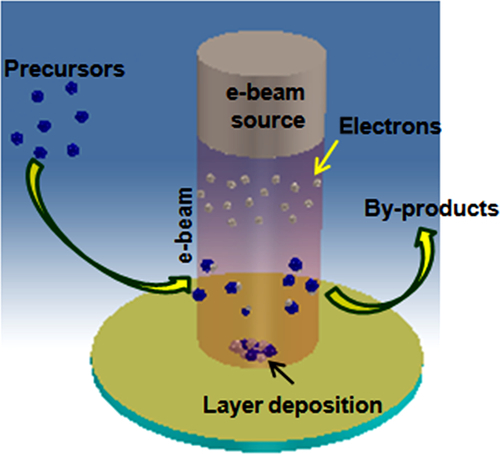
Metal carbonnitrides are the important class of compounds that are being used as coating on light metal to improve their performance. The dialkylamino-compounds of the transition metals are of special interest since they bridge the gap between the relatively stable metal alkooxides and the generally unstable metal alkyls. In addition there is the possibility that metal-nitrogen polymers would be formed, either by coordinating-polymerization in (I) (Figure 4.12), during which the lone pair of electrons on the nitrogen forms an intermolecular coordinate bond, or by using the bifunctional primary amine as in (II) (Figure 4.12). In the case of primary amine derivatives there is further possibility that coordination-polymerization will also take place. There are also some factors which might operate against polymerization. Thus in the dialkylamino-derivatives the intermolecular bonds (I) might be prevented by steric effects or by intramolecular coordination involving dπ-pπ bonds H = NR2. In the case of primary amino derivatives there is further possibility that only one of the hydrogens of the NH2-group would be replaceable by metals and this would prevent polymerization by mechanism (II). Prior to 1959 the only binary dialkylamino-compound of a transition metals or actinide element reported was the tetrakis(diethylamino)-uranium (IV) obtained by Gilman and coworkers from the reaction involving uranium tetrachloride and lithium diethylamide.91 Dermer and Fernelius prepared Ti[N(C6H5)2]4 by treating titanium tetrachloride with sodium diphenyl amide.92
It has been shown that the lithium dialkyl amide—metal chloride reaction (I) is suitable for synthesis of numerous dialkylamino-derivatives of titanium, zirconium, vanadium, niobium, tantalum, chromium, molybdenum, and tungsten (reaction scheme 4.13):
Most of the dialkylamino-derivatives may be distilled under reduced pressure although in some cases [e.g., Nb(V), Ta(V) compounds] interesting thermal decomposition occurs. The aliphatic dialkylamino-compounds are readily hydrolyzed or alcoholyzed but arylamino-derivatives are relatively more stable. Some interesting steric effects are observed in the dialkylamino-compounds while in the primary amino-compounds a number of polymeric derivatives are obtained. Only in the case of Zr(NMe2)4 is there any evidence of polymerization at the boiling point of benzene and it is noteworthy that the compound is significantly less volatile than the corresponding titanium derivative. From a consideration of the steris effects demonstrated in the aminolysis of these tetrakis-(dialkylamino)-derivatives it is deduced that the absence of polymerization is a consequence of the powerful shielding of the central atom by the dialkylamino group.
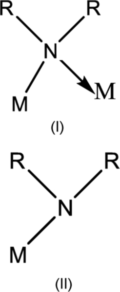
In Table 4.1 some of the metallorganic compounds of type tetrakis(diethyl)-aminometal (M(N(C2H5))4) are mostly used for deposition of such compounds; for example, Zr(N(C2H5)2)4 and Ti(N(C2H5)2)4 are used for coating of ZrCN and TiCN, respectively. Using plasma-assisted CVD method the deposition temperature of such compounds is been drastically reduced to 180 °C which is very useful for coating metals/alloys.93,94
Table 4.1
Metalorganic Compounds of Type Tetrakis(Diethyl)-Aminometal of Titanium and Zirconium
| Sr. No. | Compound | Physical State | Boiling Point (ºC/mmHg) |
| 1 | Ti(NMe2)4 | Yellow liquid | 50/0.05 |
| 2 | Ti(NEt2)4 | Orange liquid | 112/0.1 |
| 3 | Ti(NPrn2)4 | Red liquid | 150/0.1 |
| 4 | Ti(NBu1/2)4 | Red liquid | 170/0.1 |
| 5 | Zr(NMe2)4 | White solid (mp. 70 °C) | 80/0.05 |
| 6 | Zr(NEt2)4 | Green liquid | 120/0.1 |
| 7 | Zr(NPrn2)4 | Green liquid | 165/0.1 |
| 8 | Zr(NBu1/2)4 | Green solid | 180/0.1 |
4.3.2.3 SiC precursors
SiC is the most widely used material, especially for corrosion-resistance application. So in this section we provide a detailed description of organosilicon compounds synthesis as SiC precursor is given.95 In the past many SiC coatings have been produced by the CVD technique; however, most SiC coatings deposited have been grown at relatively high temperatures of 1300-1380 °C and at atmospheric pressure, using separate precursors for Si and C.96–100 For instance, SiH2 or Si2H6 have been used for Si, and CH4 or C3H8 have been used for C.101 Combination of methyltrichlorosilane (CH3SiCl3 or MTS) and hydrogen is the most popular single molecular precursor, partially because methyltrichlorosilane contains the same number of silicon and carbon atoms. To achieve an optimal oxidation resistance, it is important that stoichiometric SiC is deposited. Although the C/Si molar ratio in methyltrichlorosilane is one, deposition of silicon with SiC is encountered at a temperature below 1000 °C, whereas carbon is deposited with SiC above1600 °C. The mechanism of SiC deposition can be regarded as two independent subsystems, that is, the deposition of carbon and the deposition of Si.102 Equal rates will result in stoichiometric SiC. Detailed knowledge of the kinetics in the gas phase and on the surface is, however, limited, especially for chlorine-containing SiC precursors like CH3SiCl3. The gas phase kinetic for the SiH4-hydrocarbon system is relatively well understood,103,104 but more knowledge of the surface chemistry is needed. The use of methyltrichlorosilane requires a source of hydrogen gas to combine with the chlorine atoms liberated during decomposition. The reaction forms hydrogen chloride as a by-product, which must be removed, thus requiring a scrubber as part of the equipment. Since the hydrogen chloride is corrosive all equipment must be corrosion resistant. Table 4.2 shows examples of conventional SiC precursors and their applications.
Table 4.2
Conventional SiC Precursors and Their Applications
| SiC Precursors | Condition of Synthesis | Application | |
| Temperature (°C) | Pressure (kPa) | ||
| CH3SiCl3 | 1323-1673 | n.r. | Coating |
| 1200 | 1.7 | Coating | |
| 973-1073 | 10-35 | ||
| 973-1173 | 10-100 | Composite (CVI) | |
| 1052-1070 | 2-13.3 | ||
| CH3SiCl3/CH4 | 1273-1523 | 4.6 | Coating |
| SiCl4/CH4 | 1200-1400 | 100 | Coating |
| (CH3)2SiCl2 | 1473-1600 | n.r. | Coating |
| SiCl4/carbon | 1300-1500 | 100 | Coating |
| SiH4/CxHy | 1573-1723 | 100 | Electronic |

n.r. = not reported.
Recent practice of using halogen-free single source compounds in CVD is, in some cases, enjoying low deposition temperature and accurate stoichiometry. Since the single molecular precursor already has a Si![]() C bond in the precursor itself, it does not need further activation energy to make a Si
C bond in the precursor itself, it does not need further activation energy to make a Si![]() C bond in the film, resulting in epitaxial temperatures below 1000 °C. Many research groups have thus performed growth of SiC either on different substrates using single precursors: Golecki et al.105 had grown single crystalline epitaxial cubic(100) films on (100) Si substrates at 750 °C by low pressure CVD, using methylsilane, CH3SiH3 and H2. He got the stoichiometric SiC composition at low temperature because methylsilane can generate vapor that is stable at room temperature. The drawbacks of methylsilane are very low boiling point (− 57 °C) pyrophoric and irritant gas and commercially available at high cost. Steckl et al.106 have grown the cubic SiC on Si using the precursor trimethylsilane, and they have investigated the effect of temperature, flow rate of precursor on on-axis Si (100) and off-axis Si(111) substrates.
C bond in the film, resulting in epitaxial temperatures below 1000 °C. Many research groups have thus performed growth of SiC either on different substrates using single precursors: Golecki et al.105 had grown single crystalline epitaxial cubic(100) films on (100) Si substrates at 750 °C by low pressure CVD, using methylsilane, CH3SiH3 and H2. He got the stoichiometric SiC composition at low temperature because methylsilane can generate vapor that is stable at room temperature. The drawbacks of methylsilane are very low boiling point (− 57 °C) pyrophoric and irritant gas and commercially available at high cost. Steckl et al.106 have grown the cubic SiC on Si using the precursor trimethylsilane, and they have investigated the effect of temperature, flow rate of precursor on on-axis Si (100) and off-axis Si(111) substrates.
The use of trimethylsilane to form amorphous or polycrystalline SiC films is also known in the art. For instance, Kaplan et al.107 have described the formation of SiC coatings on video disks using trimethylsilane in a glow discharge CVD process. Trimethylsilane gas is colorless, noncorrosive, and nonpyrophoric precursor, but excess carbon deposition is formed during SiC deposition. There are other organosilane type precursors available to get SiC film. Yasui et al.108 have used dimethylsilane to get cubic SiC film while Avigal et al.109 have grown the SiC on the Si-SiC-C system using different precursors such as tetramethylsilane (b.p. = 26-28 °C), diethylsilane (b.p. = 56 °C), and tripropylsilane (b.p. = 171 °C). The SiC has been grown in the range of 700-1400 °C regardless of the atmosphere, but the films are contaminated with inclusions of silicon and free carbon. They found that pyrolysis of tetramethylsilane in H2 produces less free carbon than in the presence of helium. It was also noticed that at lower temperature the CH3 deposits more free carbon while at higher temperatures the C3H7 deposits more free carbon. Tetramethylsilane, diethylsilane, and tripropylsilane are stable at room temperature. First two precursors have low vaporization temperature and tripropylsilane has high vaporization temperature. All three precursors are safe to handle but are costly.
Jeong et al.110 have prepared thin films of cubic SiC on Si(100) by high vacuum MOCVD using diethylmethylsilane [DEMS, (C2H5)2(CH3)SiH] (b.p. = 78 °C) at various temperatures. DEMS is stable at room temperature, nontoxic, and not explosive. With a deposition temperature of 900 °C, relatively well oriented 3C-SiC layers were obtained. When the deposition temperature was increased from 700 to 900 °C, there was an improvement in crystallinity and grain size. However, above 900 °C crystallinity decreased with increasing temperature and growth time due to a crystal shape change. These results show that the deposition temperature and time are important factors for influencing film crystallinity and carbon deposition.
Kim et al.111 have used a new precursor dimethylisopropylsilane [(CH3)2CHSiH(CH3)2] (b.p. = 66-67 °C) to deposit cubic SiC films on Si(100) and Si(111) substrates at the temperature range of 750-970 °C using low-pressure organometallic chemical vapor deposition (LP-OMCVD). They found that at low temperature amorphous SiC films and free carbon were deposited. They got cubic-type SiC films on uncarbonized Si(100) surfaces at 850 °C and a polycrystalline cubic SiC film on a carbonized Si(100) substrate at 960 °C. But they were not successful in obtaining epitaxial growth of cubic SiC on carbonized Si (100) using the same precursor.
There are many synthesis routes described in literature of above organosilane precursors. We will discuss some of the economical synthesis routes of potential organosilicon precursors for SiC. In general in these methods first chlorine substituted silanes are taken that may be a product or by-product of a technical process (for example, methyldichlorosilane is a technical product which is obtained as a by-product of the direct synthesis).
The organic groups can be introduced into these chlorinated silanes by the Grignard process (scheme 4.1) in which only the Si![]() Cl bond (but not the SiH bond) is involved. The Grignard reaction is of fundamental importance for the whole field of organosilicon chemistry.112 It utilizes organomagnesium compounds to transfer organic groups to silicon (reaction scheme 4.14):
Cl bond (but not the SiH bond) is involved. The Grignard reaction is of fundamental importance for the whole field of organosilicon chemistry.112 It utilizes organomagnesium compounds to transfer organic groups to silicon (reaction scheme 4.14):
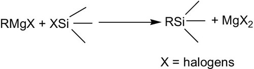
Conversely, the chlorine in chlorosilanes already containing organic substituents can be replaced by hydrogen (scheme 4.2). Reactions with metal hydrides, such as lithium tetrahydroaluminate,113 lithium hydride,114 sodium hydride,115 and the reactive aluminum tetrahydroborate Al(BH4)3116 are most suitable for the reaction, which proceeds in principle as follows (reaction scheme 4.15):
The action of aluminum tetrahydroborate on trimethylchlorosilane can be represented schematically in reaction scheme (4.16):
The reaction with sodium hydride dispersed in mineral oil or another inert high-boiling hydrocarbon requires temperatures of 175-350 °C.115 The addition of catalysts can lower the reaction temperature or increase the yield. Alkylborons, boricacid esters, and triethylaluminum are suitable catalysts.117,118 An interesting embodiment of the substitution reaction consists in passing the halogen compound through a eutectic melt of an alkali-metal halide containing lithium hydride. In this way, at 360-400 °C dimethyldichlorosilane yields dimethylsilane (CH3)2SiH2 with 95% conversion and 89% yield.119
Boo et al.120 have used a new single molecular precursor 1,3-disilabutane containing two silicons and carbon atoms. They have grown the Cubic SiC films on the Si(100) and Si(111) substrates in the temperature range 650-900 °C by LP-OMCVD using this precursor. Polycrystalline cubic SiC films were formed on Si(100) substrates at such a low temperature as 650 °C. The films obtained on carbonized Si(100) substrates at temperatures higher than 850 °C show improved crystallinity in their X-ray diffraction patterns. On the other hand, highly oriented SiC films in the [111] direction were formed on carbonized Si(111) substrates at 900 °C.
The precursor 1,3-disilabutane which contains silicon and carbon atoms at a ratio of 1:1 was obtained by reduction of 1,1,3,3-tetrachloro-1,3-disilabutane. The synthesis of 1,1,3,3-tetrachloro-1,3-disilabutane was reported by Jung121 as follows.
The reaction of (chloromethyl) methyldichlorosilane with elemental silicon and hydrogen chloride using copper as a catalyst and cadium as a cocatalyst leads to the attachment of a silicon atom to the organochlorosilane molecule, producing 1,1,3,3-tetrachloro-1,3-disilabutane. Reduction of this compound with metal hydrides (e.g., lithium aluminum hydride) in ether replaces the chlorine atoms with hydrogen atoms. The final compound is 1,3-disilabutane.122
Steckl et al.123 have grown the SiC films on different substrates using silacyclobutanes. In these precursors deposition of carbon occurs in SiC film, because of Si:C ratio is 1:3. Silacyclobutane is synthesized according to reaction scheme (4.17).

The 3-halopropyltrichlorosilanes are prepared by addition of trichlorosilane to an allylhalide with chloroplatinic acid as catalyst. The 1,1-dichloro-1-silacyclobutane124,125 can be prepared from Cl3SiCH2CH2CH2Cl using magnesium powder. This 1,1-dichloro- 1-silacyclobutane is reduced using lithiumaluminumhydride in n-butyl ether at 0 °C to get silacyclobutane, (CH2)3SiH2.
Another precursor that is used because of the same number of silicon and carbon atoms is 1,3-disilacyclobutane. Larkin et al.126 and Chadder et al.127 have used this precursor to get stoichiometric SiC, but this precursor needs relatively high temperature to grow SiC film and it has tedious synthesis route. It can be prepared by the LiAlH4 reduction of 1,1,3,3-tetrachloro-1,3-disilacyclobutane. This 1,1,3,3-tetrachloro-1,3- disilacyclobutane is obtained by pyrolyzing 1,1-dichloro-1-silacyclobutane128 at 700 °C according to methods described by Nametkin et al.129 This type of pyrolysis reaction is of considerable interest and it is postulated to go through the [Cl2Si = CH2] intermediate.
The process is given in reaction scheme (4.18):

The strained cyclic molecule 1,3-disilacyclobutane allows to grow β-SiC film at a temperature > 300 °C lower than possible with a similar straight chain reagent. It is proposed that decomposition of the cyclic precursors directly produces intermediates that can lead to deposition of stoichiometric SiC. The synthesis routes of cyclic compounds are completed and tedious. Cyclic precursors are promising for both the deposition of single crystal films at high temperature as well as for polycrystalline and single crystal films at low temperature.
Takahashi et al.130 have used the hexamethyldisilane (HDMS) (b.p. = 112-114 °C) to get cubic SiC films on Si and other substrates. At temperatures lower than 1100 °C the growth rate is limited by thermal decomposition of HMDS molecules. At higher temperatures, the growth rate is limited by thermal diffusion of (CH3)n-Si-H4 − n species through stagnant gas layers at the substrate surface. Temperature dependence of crystallinity of grown films reveals that the gas system is effective for low temperature epitaxy. With and without buffer layers, single-crystalline 3C-SiC containing twinnings were grown on a Si(111) substrate at 1100 °C. In the case of Si(100) substrates, single crystals were grown only with a buffer layer. Even though growth temperatures were as low as 1100 °C, crack lines were observed in a 5 μm thick layer grown on a Si(111) substrate. HDMS is stable at room temperature and gives codeposition of free carbon with SiC film.
Shen et al.131 have described a method for making the SiC ceramic precursor compound, 2,4,6-trimethyl-2,4,6-trisilaheptane (TMTSH), which comprises reducing chloromethyl-dimethylchlorosilane with lithium aluminum hydride in a suitable solvent to form chloromethyldimethylsilane; reacting the chloromethyldimethylsilane with magnesium to form the corresponding Grignard reagent; coupling the Grignard reagent with methyldichlorosilane; and recovering 2,4,6-trimethyl-2,4,6- trisilaheptane. It has been demonstrated that the deposition of SiC occur on a substrate at deposition temperature 1400 °C and pressure about 760 Torr. Whereas for deposition of SiC at low temperature such as at 600 °C, low system pressure about 10− 10 Torr was required. The SiC precursor is a chlorine-free, single molecular compound rather than a polymer, oligomer, or mixture of compounds, oligomers, or reaction products. The main chain of the compound is composed of repeating Si-C units. The carbon-to-silicon ratio in the precursor compound is 7:3. This chlorine-free carbosilane contains no elements other than silicon, carbon, and hydrogen and is therefore highly suitable for CVD and CVI applications. TMTSH provides higher deposition rate and higher yield than can be achieved with methyltrichlorosilane. Other benefits include ease of preparation, handling, storage, and transportation. The composition is noncorrosive. In addition, the silicon-to-carbon (Si:C) ratio is relatively low and can be controlled by control of parameters which affect the deposition rate. Carbon content of the coating can be varied from a slight excess of carbon to near stoichiometric ratio of silicon to carbon using nitrogen as a carrier gas. No solvents or reactive secondary gases are required. A carrier gas is not essential, but nitrogen, hydrogen, argon, or other suitable carriers can be used to vary flow rates and partial pressure of the TMTSH. Nitrogen, hydrogen, or mixtures are used to control the stoichiometry of the coating.
An alternate of the single molecular precursors are the organometallic polymer precursors, especially polysilanes and polycarbosilanes. These polymer compounds that contain polysilanes and polycarbosilanes must be volatile for CVD use. Generally the polymers of sufficiently high molecular weight, crosslinks before significant volatilization occurs. Such cross-linking before volatilization is highly undesirable for the application under consideration, where excessive silicon and carbon remain in polymer and do not come in vapor form. Presently research is going on to get a polymer precursor that gives stoichiometric SiC film and can be used in the CVD process, but so far no precursor has been obtained in our knowledge which fulfills all criteria of an ideal precursor.
In the commercially available precursors for SiC, presently precursors are available with the name CVD 2000 and CVD 4000.132 CVD 2000 is a single molecular organometallic liquid precursor while CVD 4000 is a single component liquid precursor having the basic structure of [SiH2-CH2]n. Their synthesis routes have not been disclosed and have high cost. In our lab we have developed an economical synthesis process to synthesize a precursor that is halogen free and stable in atmosphere and low sublimation temperature. Its synthesis involves reaction of dichloromethane with silicon powder having a specific size in a specially designed fluidized bed. A schematic diagram of fluidized bed is given in Figure 4.13. The typical reaction involves the reaction of silicon with dichloromethane at 350 °C, and the product was condensed and collected in a vessel. The collected product was distilled at 150 °C at atmospheric pressure, and later on distilled product was reduced with lithium aluminum hydride. The final compound that was named CVDP has shown up to 95% volatility at 200 °C. This compound was further used for graphite substrate coating and has given promising results. Currently we are not revealing much about the synthesis and coating process since it is in a process of publication/patent. A comparative study of precursors CVD 2000 and CVD 4000 with other commercially available precursors is given in Table 4.3.

Table 4.3
Comparison of Different SiC Precursors
| CVD 2000 | CVD 4000 | MTS | Silane | Organometallic Precursors Developed in our Lab | |
| Precursors | Only CVD 2000 | Only CVD 4000 | MTS plus H2 (in exact ratios) | Silane plus methane (CH4) | Mixture of organosilicon compounds (CVDP) |
| Precursors hazards | Flammable (FP = 51 °C) | Flammable (FP = 9 °C); air, moisture reactive at 140 °C | Corrosive, toxic, flammable (FP = 3 °C); moist air and water reactive at 20 °C | Pyrophoric | Easy to handle; noncorrosive and nontoxic |
| % SiC in precursor | 63% SiC (25% C, 12% H) | 91% SiC (9% H) | 27% SiC (71% Cl, 2% H) | Silane—87% SiC (13% H), Silane + Methane—83% SiC (17% H2) | (CVDP) Approx. 83% SiC |
| By products of the CVD process | H2 and Methane (CH4) | H2 | HCl (highly corrosive) as well as H2 and silanes | H2 | H2, CO/CO2 |
| Coating composition Si:C | Varies with substrate temp., 1:1 + 5—15% carbon | 1:1 ± 0.5% | 1:1 ± 1.2% plus Cl and trace metals | 1:01 | 1:1 ± 5%, no trace metal deposition |
| Deposition temperature | 800-900 °C | 600-900 °C | 1000-1400 °C | 1200-1500 °C | 700-1000 °C |

4.4 Liquid Delivery Systems: Effect of Solvent
In most of the cases of OMCVD, the solid/liquid precursors were heated under reduced pressure for vaporization. The solids can vary in their shape or crystallinity, which can affect their volatility. Various systems of vaporization have been developed and adapted for use with pure liquid precursors or solutions. The first system described is that of the bubbler, where the precursor is pulled through the liquid by the bubbling of a gas. The liquid can be heated (and the entire line, up to the reaction chamber to avoid recondensation) or cooled according to the volatility of the precursor and the desired precursor flow. This system was adapted with regulators and sensors in order to have a partial pressure of precursor constant in the furnace. It is the simplest and widely used system. The second system used for precursor delivery is direct liquid injection system. A direct liquid injection system has been described where the solution is injected by syringe directly into a vaporization chamber. The syringe can be replaced by volumetric pumps, mixing the solvent and precursor and delivering the solution in a constant fashion or according to a preprogrammed set of instructions. The third kind of system is the improvement of liquid injection system. An improvement to liquid injection systems in terms of precision was the development of pulsated liquid injection where micro-quantities of precursor solution are injected sequentially. A comparative OMCVD Pt coating study under very similar experimental conditions, employing two precursor delivery systems, has been reported: comparing Pt OMCVD films obtained from MeCpPtMe3 with a TriJet™ liquid delivery system and a conventional bubbler.133,134 The properties of the deposits grown using the two different precursor delivery systems were found to be very similar, making a comparison between the two deposition techniques nontrivial. Although the use of a conventional bubbler leads to fast deposition of Pt films, controlling the amount of consumed precursor is difficult. Conversely, the liquid injection system enables perfect control over the quantity of precursor used, but results in a slower rate of film growth. In this study, the use of cyclohexane gave positive results due to its low chemical interference with the oxidative decomposition of platinum precursor. Even for liquid precursors, the use of a solvent is often needed to control precursor delivery. Aerosol flash evaporation using solutions give good results in terms of accuracy. In general, the choice of solvent remains unexplained and its effects upon deposition are not described in detail. They can play a role by interacting with the second even the first sphere of metal coordination and thus stabilize the metal complex. It is also possible to dissolve in the solution a suitable quantity of free ligand in order to stabilize the complex. Another potential effect of solvent is to increase the vapor pressure of the precursor by an azeotropic effect. The more commonly used solvents are: acetylacetone, pentane, cyclohexane, tetrahydrofuran (THF), and n-hexane.
4.5 Organometallic Precursor Chemistry
Single source precursors have been preferred over multisource precursors to overcome the problem of vapor phase control and homogeneity of the unstable precursors. The single source precursor is contained in a closed container under an inert gas at room temperature; a small quantity of the precursor is introduced into an evaporator held at a high temperature, where it is being flash volatized. This allows fast evaporation of the precursor and a shorter delivery time of the vapor precursor to the reaction zone, which also leads to a higher growth rate (e.g., mm/s) than the conventional bubbler method. This technique also enables the use of precursors with lower volatilities than the classical multisource precursors and the composition of the vapor is the same as the mixture of precursors, thus allowing the synthesis of multicomponent films (including those containing Ba, and rare earth elements) with a better control of composition and stoichiometry and higher reproducibility. The use of single source precursors also simplifies the control of process parameters of the MOCVD process.
Volatility and decomposition of the precursor is a key stage in the formation of the coating. Fast and complete precursor decomposition usually ensures that a coating of good purity and a good quality is obtained. The chemical nature of the precursor is the dominant factor here, requiring stability under the vaporization conditions and decomposition only under the deposition conditions. Selvakumar et al.135 have established that volatility of CVD precursors are the important factor for effective coating. The most important quantitative characteristic of volatility is the pressure of saturated vapor of the compound at defined temperature. Thermogravimetry method has been used for determination of vapor pressure, enthalpies of sublimation and evaporation, and solid-state kinetics of chemical reactions for volatile precursors. Transpiration technique, which is also known as the gas entrainment technique, was used for determination of vapor pressure over a wide range of pressures. In this study the kinetic parameters for sublimation and evaporation of volatile metal complexes by nonisothermal studies were evaluated. Different organometallic compounds of Fe, Cr, Cu, Si, Al, Ni, Ga, Sc, La, Mg, Mn, Y, Zr, and Sr exhibited substantial volatility below 600 K without residue. The added advantage is their excellent air/moisture stability, making it amenable for use under ambient conditions. The complete volatility and low temperature range of sublimation/vaporization below 600 K for all studied compounds make it suitable for use at a lower deposition temperature of the substrate in the CVD reactor.
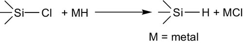
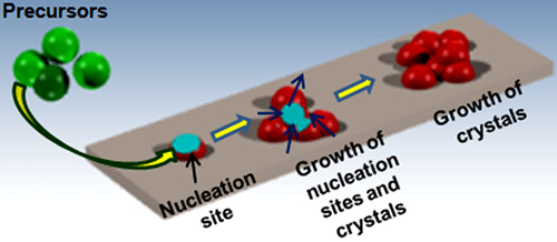
4.6 Nucleation and Growth Mechanisms
According to the operating conditions used, the precursor flow and temperature can be the main contributor to the nucleation process, that is, by the formation of new crystallites or with the growth of the initially formed crystallites136,137 (Figure 4.14). Under conditions favoring nucleation, the film obtained appears as a small crystallites, the consequent aggregation of which results in good connectivity between the grains and nearly an absence of holes and hence, a low resistivity. Under conditions supporting growth, the film is made up of large crystallites. Various physical factors influence the prevalence of nucleation or growth at the time of film formation. Due to this parameter being of a kinetic nature, the temperature is very important, the phenomena of growth and nucleation not utilizing same activation energies. The gas composition sometimes has significant effect on the nucleation. Nucleation can be supported by the nature of the substrate at the beginning of deposition and also by the nature of the gas used. For example, the addition of steam that will produce hydroxy groups; the consequences of which are limitation of atom diffusion and then of crystal growth. Nucleation is also supported by precursor “supersaturation,” obtained by increasing the precursor concentration in the phase gas. Decomposition in phase gas can also contribute to the nucleation process. Generally during deposition, small grains are formed by nucleation on the substrate surface initially; bigger grains are then formed onto this first layer. A process has been developed in order to produce smooth films with small grains throughout the thickness of the film, and for that purpose, the deposit is performed in two stages (Figure 4.14). First, the growth conditions support nucleation, the agglomeration and the formation of a smooth initial film. Second, film growth with small grains is favored. When the quantity of evaporated precursor for the formation of the initial film is reached, the operating conditions are changed; the temperature, the pressure, and the oxidizing concentration are lowered.
4.7 Coating Damage Mechanisms
A schematic illustration of the principal damage mechanisms and partial processes138 that take place between a substrate, its coating, and its environment are illustrated in Figure 4.15. The effects of oxygen attack at high operating temperature are highlighted and will be discussed in more detail; however, other aggressive species, for example, Cl2, Na2SO4, and H2, are also important.

In the case of oxygen permeation, an oxide scale may form at the substrate/coating interface, and this can be either beneficial or detrimental. If a dense compact scale is formed, it may provide additional protection against ingress of oxygen; however, the molar volume expansion of the reactant products can induce stresses which damage the protective coating. In addition, volatile species, for example, CO, N2, SiCl4, may evolve as reaction by-products and these gases must diffuse outwardly to the surface. If their diffusion is restricted, gas bubbles will form, and, under certain conditions, the internal pressures can rise to the point of disrupting the coating. If oxygen or other reactive species penetrate to the composite surface, selective attack may occur along matrix/fiber interfaces and damage the coatings that have been introduced to enhance interfacial sliding. Localized attack may progress rapidly down these interfaces and cause deterioration in overall mechanical properties. This can be a particular problem in brittle matrix composites where prior matrix cracking has occurred and in composite systems subjected to thermal or thermomechanical fatigue.
A major consideration in the application of any coating is uniform adherence between coating and substrate. Usually, the coating process is selected to provide acceptable adherence, and great care is employed to minimize or eliminate surface contamination. Coating systems must be chosen that will be thermochemically stable at operating temperature, and differences in thermal expansion between coating and substrate must be kept to a minimum. It is not always possible to balance these factors, and compromises in CTE mismatch are often accepted. The result can be an unacceptably high stress level that eventually leads to spallation or cracking. Actually, the formation of cracks, pinholes, or other coating defects is inevitable, that is, there is no perfect coating system. Thus, crack management becomes a major consideration in the development of engineered coating systems. Cracks may open and close with the application of loads or through exposure to thermal cycling. If the openings are sufficiently large at a reactive temperature, the ingress of molecular oxygen or other aggressive species will lead to internal damage. One approach is to utilize glass sealants or employ additives that have self-healing properties during high temperature exposure. Coatings which employ sealants can be effective; however, finding a sealant that is functional over a large temperature range is a challenge.
Oxygen permeability was identified as an important criterion in the selection of protective coatings. Composites are particularly susceptible to attack along matrix fiber interfaces or internally within matrix cracks. Thus, if aggressive species penetrate the coating, they can rapidly diffuse into the interior of the composite and cause damage. The result of internal oxidation and interface degradation generally, and sometimes significantly, reduces mechanical performance. A by-product of many interface reactions is a volatile gas. If these internally generated gases are unable to diffuse outwardly to the surface, gas bubbles will form and pressures can build to the point where damage occurs. Ceramic composites/coatings are being considered for expanded use in combustion system hot sections or in gas discharge regions. The presence of Na, S, or V impurities in the combustion products can lead to molten sulfate vanadate condensates which are extremely corrosive. Enhanced oxide solubility in these deposits is capable of rapidly degrading coating effectiveness, which may increase oxygen permeation or enable attack by other aggressive species. While thermochemical compatibility between aggressive environments and the composite is usually the primary factor in the selection of a coating system, mechanical stability is often the determining factor in whether a coating can provide its intended function. Large differences in CTE can usually not be tolerated and will limit thermal cycle resistance. The application of graded interfaces can be beneficial when properly designed to minimize certain types of damage, such an interlaminar shear or across-ply cracking. However, grading is not generally an answer to the amelioration of large CTE mismatches for the prevention of in-plane cracking.
Since perfect coatings are not a practical reality, some sort of crack or flaw management philosophy is an essential part of coating design. Thinner coatings produce smaller cracks that are a factor in controlling the ingress of molecular species. The coating must be designed so that the cracks heal themselves at operating temperatures, or sealants must be employed to fill and close openings.
4.8 Conclusion and Outlook
Protective layer coatings of refractory ceramics on substrate materials are applied usually to protect the substrate materials in harsh conditions such as oxidative and corrosive environments. Based on application, coating materials having desired properties such as high melting point, good thermal and chemical stability, and thermal expansion coefficient close to the substrate material are chosen. The class of materials extensively used for protective coatings includes carbides and nitrides of transition metals (titanium, zirconium) and of nonmetal (silicon). Furthermore, oxides such as silica, alumina, titania, and zirconia, are also applied for protective coatings. Among the several coating methods which are available to derive coating of such materials, the CVD process based on organometallic precursors is very promising by virtue of cost effectiveness and being environmentally safe. Additionally, this process is advantageous to derive high-quality protective coatings over the substrates without the substrate degradation. There are different modes of CVD such as LCVD, UVCVD, PECVD, EBCVD, FBCVD, ALD, and IACVD that can utilize organometallic precursors for protective coating of the substrates in an economical and safer manner. The selection, synthesis, and liquid delivery system of organometallic precursors are of utmost importance for desired coating. Significantly large numbers of synthesis methods are available for synthesizing organometallic precursors using cheaper chemicals. In addition, efficient liquid delivery systems, such as bubbler, direct liquid injection by syringe, preprogrammed volumetric pumps, and pulsated liquid injection for injecting organometallic precursors into the vaporization chamber, are also available. Therefore, the MOCVD technique has the potential for producing a good-quality protective coating on substrates in an economical and environmental friendly manner.