Measurement and Meters
Characteristics to be considered when evaluating a meter include: achievable uncertainty, comparative cost, use acceptance and specific use, repeatability, maintenance costs, operating cost, few or no moving parts, ruggedness, service life, rangeability, style to meet fluid property problems, pressure and temperature ratings required, ease of installation and removal, power required, pressure loss caused by meter (running and stopped), and how well calibration can be proved. Meter selection and application are considered in this chapter. The characteristics of different types of meter (orifice, flow nozzle, Venturi, Coriolis, ultrasonic Doppler) are summarized. Meter characteristics discussed include meter factor, rangeability, linearity, repeatability, and hysteresis.
Keywords
Coriolis meter; flow meter; flow nozzle meter; hysteresis; linearity; meter factor; orifice meter; rangeability; repeatability; ultrasonic Doppler meter; Venturi meter
After identifying—and addressing the care of—all effects of fluids and the flow signature for a specific application, meter selection and application can be attacked. Several general considerations as well as specific characteristics of individual meters will be reviewed.
Meter Characteristics
Comparing Meters
Characteristics to be considered when evaluating a meter include: achievable uncertainty, comparative cost, use acceptance and specific use, repeatability, maintenance costs, operating cost, few or no moving parts, ruggedness, service life, rangeability, style to meet fluid property problems, pressure and temperature ratings required, ease of installation and removal, power required, pressure loss caused by meter (running and stopped), and how well calibration can be proved.
No single meter will have all of the characteristics desired, but candidates can be evaluated by going through such a list for each meter under consideration and then deciding which of the factors are of prime importance for the particular flow measurement problem. A procedure something like the following may be helpful:
1. List, for each candidate meter, the characteristics of importance.
2. Define how important each is by assigning a weighting factor (such as from 10 for very important to 0 for no importance).
3. Assign a similar rating number to show how well the meter will perform to meet specific needs of the application.
4. Multiply the weighting factor by the performance factor, and add all the totals.
Comparing the totals for various meters will provide a rank ordering. (This same concept can be applied to the total metering system problems including considerations for flow, fluid, installation, maintenance, etc.)
There are no industry-required standards or testing facilities where meter tolerances can be validated and a ranking of meters published. Even if such a facility were available, it would be impossible to make a test expressing all possible uses of a meter. A simple case in point: A test on a gas may not relate to a liquid metering problem or vice versa, even with consideration of the Reynolds number effect. Therefore, specific information may not be available, but knowledge is available in the industry to give guidance on the probabilities of success for a given meter in a given application.
Specific meters prove useful with specific applications and/or fluids—or they quietly disappear from the marketplace. The flow measurement fraternity is a relatively conservative group. New meters based on a new principle have a long road to acceptance under the best of circumstances. The history of every meter in use today has followed this road. A meter must provide acceptable performance/cost ratios, considering initial cost plus the other required investments in proper installation, operation, and maintenance, or it will not complete the trip down the acceptance road.
Types of Meters
There are many ways that types of meters can be listed; they are listed here by their individual names under general categories, since there are significant differences between the meters in the same category (i.e., differential head meters of the orifice, flow nozzle, Venturi, and Pitot tube types; this is true for the linear meter). They are listed in random order, and there is no significance to the order.
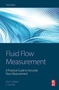
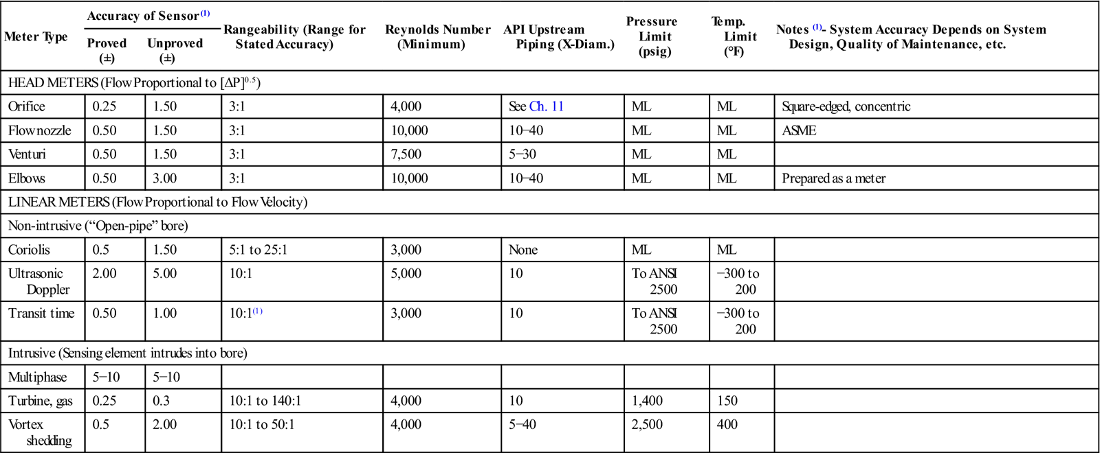
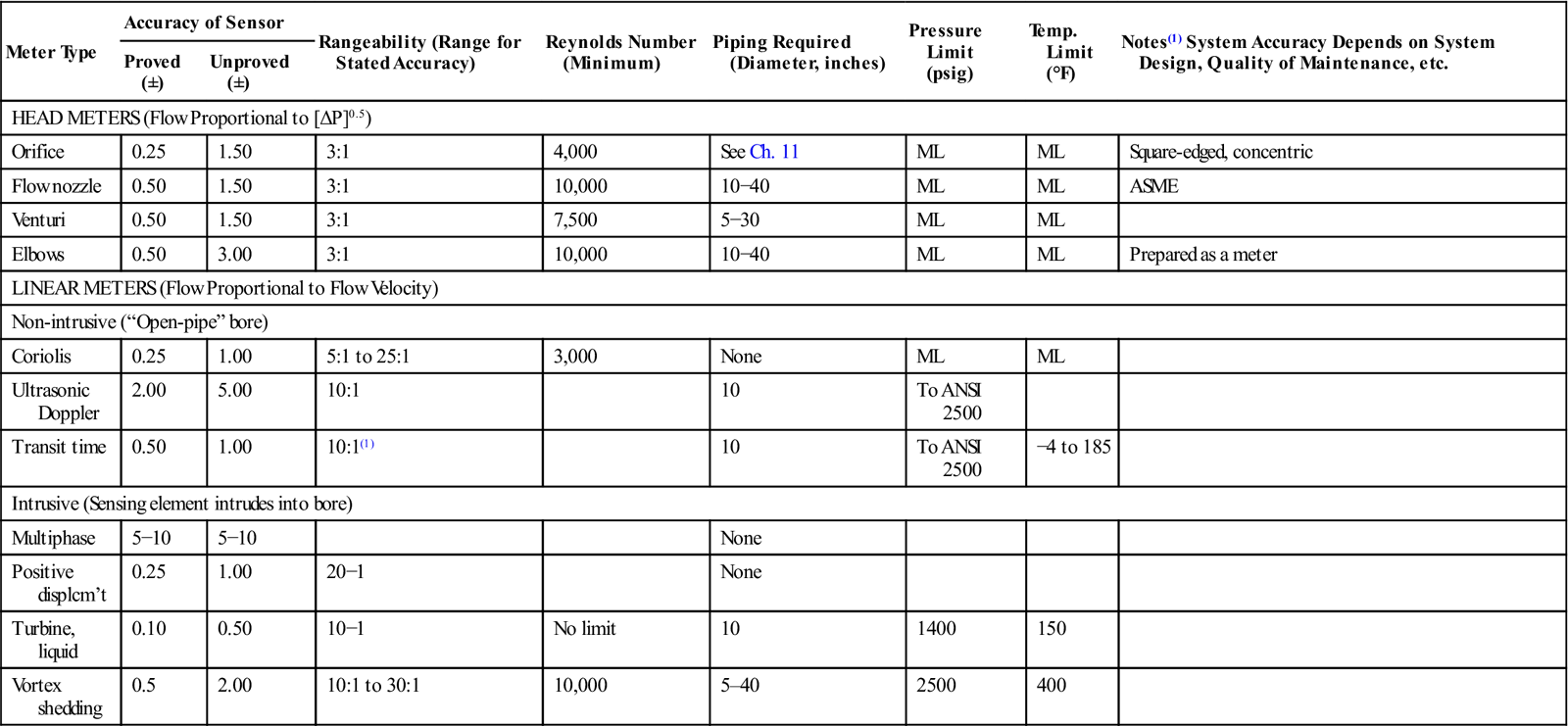
The following charts show major flow meters and their salient characteristics. These are by no means definitive since they list only general categories and performances. Most manufacturers claim performance better than tabulated here—but values in the tables are more typical of actual field conditions for properly installed and maintained meters. For specific applications, the comments may or may not apply. Once again, reference should be made to relevant industry standards and data, manufacturers’ information, and the experience of others to evaluate flow metering for a given application. But these tables provide a starting point (Figure 10-1, Tables 10-1, 10-2).

Table 10-1
Characteristics of Meters for Gas Measurement
| Meter Type | Accuracy of Sensor(1) | Rangeability (Range for Stated Accuracy) | Reynolds Number (Minimum) | API Upstream Piping (X-Diam.) | Pressure Limit (psig) | Temp. Limit (°F) | Notes (1)- System Accuracy Depends on System Design, Quality of Maintenance, etc. | |
| Proved (±) | Unproved (±) | |||||||
| HEAD METERS (Flow Proportional to [ΔP]0.5) | ||||||||
| Orifice | 0.25 | 1.50 | 3:1 | 4,000 | See Ch. 11 | ML | ML | Square-edged, concentric |
| Flow nozzle | 0.50 | 1.50 | 3:1 | 10,000 | 10−40 | ML | ML | ASME |
| Venturi | 0.50 | 1.50 | 3:1 | 7,500 | 5−30 | ML | ML | |
| Elbows | 0.50 | 3.00 | 3:1 | 10,000 | 10−40 | ML | ML | Prepared as a meter |
| LINEAR METERS (Flow Proportional to Flow Velocity) | ||||||||
| Non-intrusive (“Open-pipe” bore) | ||||||||
| Coriolis | 0.5 | 1.50 | 5:1 to 25:1 | 3,000 | None | ML | ML | |
| Ultrasonic Doppler | 2.00 | 5.00 | 10:1 | 5,000 | 10 | To ANSI 2500 | −300 to 200 | |
| Transit time | 0.50 | 1.00 | 10:1(1) | 3,000 | 10 | To ANSI 2500 | −300 to 200 | |
| Intrusive (Sensing element intrudes into bore) | ||||||||
| Multiphase | 5−10 | 5−10 | ||||||
| Turbine, gas | 0.25 | 0.3 | 10:1 to 140:1 | 4,000 | 10 | 1,400 | 150 | |
| Vortex shedding | 0.5 | 2.00 | 10:1 to 50:1 | 4,000 | 5−40 | 2,500 | 400 | |
(1)Extended low-flow meters rangeability to 50:1; ML=Material limit
Table 10-2
Characteristics of Meters for Liquid Measurement
| Meter Type | Accuracy of Sensor | Rangeability (Range for Stated Accuracy) | Reynolds Number (Minimum) | Piping Required (Diameter, inches) | Pressure Limit (psig) | Temp. Limit (°F) | Notes(1) System Accuracy Depends on System Design, Quality of Maintenance, etc. | |
| Proved (±) | Unproved (±) | |||||||
| HEAD METERS (Flow Proportional to [ΔP]0.5) | ||||||||
| Orifice | 0.25 | 1.50 | 3:1 | 4,000 | See Ch. 11 | ML | ML | Square-edged, concentric |
| Flow nozzle | 0.50 | 1.50 | 3:1 | 10,000 | 10−40 | ML | ML | ASME |
| Venturi | 0.50 | 1.50 | 3:1 | 7,500 | 5−30 | ML | ML | |
| Elbows | 0.50 | 3.00 | 3:1 | 10,000 | 10−40 | ML | ML | Prepared as a meter |
| LINEAR METERS (Flow Proportional to Flow Velocity) | ||||||||
| Non-intrusive (“Open-pipe” bore) | ||||||||
| Coriolis | 0.25 | 1.00 | 5:1 to 25:1 | 3,000 | None | ML | ML | |
| Ultrasonic Doppler | 2.00 | 5.00 | 10:1 | 10 | To ANSI 2500 | |||
| Transit time | 0.50 | 1.00 | 10:1(1) | 10 | To ANSI 2500 | −4 to 185 | ||
| Intrusive (Sensing element intrudes into bore) | ||||||||
| Multiphase | 5−10 | 5−10 | None | |||||
| Positive displcm’t | 0.25 | 1.00 | 20−1 | None | ||||
| Turbine, liquid | 0.10 | 0.50 | 10−1 | No limit | 10 | 1400 | 150 | |
| Vortex shedding | 0.5 | 2.00 | 10:1 to 30:1 | 10,000 | 5–40 | 2500 | 400 | |
(1)Extended low-flow meters rangeability to 50:1; ML=Material limit
Flow Meter Specification Terms
Meter accuracy is a much-abused term. Manufacturers often default to it for “selling shorthand,” but those specifying and buying meters to measure flow should be aware of several caveats.
Consideration of meter characteristics shows clearly that simply relying on a manufacturer’s statement of accuracy is indeed an incomplete and inadequate way to evaluate and compare meters. And, as stated, proper determination and application of accuracy, rangeability, linearity, repeatability, and hysteresis data are basic but still only part of the job in achieving the best flow measurement; operation and maintenance must also be considered.
Meter factor is a dimensionless correction that mathematically modifies a meter’s indication to a corrected true reading based on knowledge of the flow and flowing conditions. Corrected readings may be manually calculated periodically or the meter factor automatically applied continuously. It is normally determined from a throughput test, covering the range of flows to be measured, based on a master meter or a prover.
In the first place, no meter is absolutely accurate!
There are no absolute standards of gas or liquid against which to compare a meter reading to see how closely that reading compares with what is actually flowing through the meter. Furthermore, any statement of accuracy must include not only the best possible estimate of how accurate the measurement is but also over what flow range the estimate applies. The more diligent manufacturers usually supply such detailed information. But that is only part of the problem in determining meter accuracy (Figures 10-2, 10-3).
As previously noted, it is equally vital to know and take into account the type of fluid being measured, the conditions under which the meter will be used (including fluid condition), how it will be installed, how it will be operated, and what level of maintenance will be provided. Otherwise, accuracy statements are meaningless in terms of the values actually obtainable.
Rangeability expresses the flow range over which a meter operates while meeting a stated accuracy tolerance. It is often stated as “turndown,” maximum flow divided by minimum flow over the range. For example, a meter with maximum flow (100%) of 100 gallons per minute and minimum flow (within a stated tolerance such as ±0.5%) of 10 gpm has a 10-to-1 rangeability or turndown of 10. It will be accurate ±0.5% from 10 to 100 gpm.
The meter may provide a tighter tolerance over a more limited range—say 10 to 1 within ±0.5% of actual flow as above, but 3 to 1 within the ±0.25% accuracy range. This means the user can select the tighter tolerance of ±0.25% for a range 33 to 100% flow (33 to 100 gpm).
Linearity defines how close to a specific accuracy the meter registers over a stated flow range. Its proof curve will approximate a straight line. It may be significantly inaccurate but quite linear (Figure 10-4).

It is important to point out that this characteristic was much more important prior to the widespread use of computers and electronic signal-conditioning equipment. With a computer correction device, it is possible to characterize a non-linear meter output curve provided the meter output is repeatable. Such curve characterization allows a closer fit of the readout system—even for a linear meter—to minimize calibration errors. The same procedure is used on “smart” transducers to minimize any non-linearity the transducer may exhibit as a result of temperature and/or pressure effects.
Repeatability means just what it says: how nearly the same reading a meter will provide for a series of measurements of the same quantity and procedure carried out by the same operator and the same equipment in the same location over a short period of time and given flow condition. As with linearity, it may be more important to always get the same reading for specific flow rates than it is that those readings are extremely accurate. Flow control is an example in which repeatability is more important than accuracy.
Hysteresis is closely related to repeatability. It describes what happens to meter output as a given flow rate is approached from larger and smaller rates. For example, suppose a flow rate of 80 gpm is increased to 100 gpm, and a meter then registers 99 gpm. Now the flow rate increases to 120 gpm and returns again to 100 gpm; the meter registers 101 gpm. Its hysteresis is ±1 gpm, and the dead band is 2 gpm at a 100 gpm flow rate.