11
SystemVerilog
11.1 Introduction
After studying Verilog in detail, let’s go one step further and learn about SystemVerilog. Due to some additional features compared to Verilog, this becomes attractive for fast-evolving technologies and industries are now more interested. SystemVerilog obtained standardization by the IEEE 1800 in 2018 as a hardware description and hardware verification language [1] which is an extension of Verilog used to model, design, simulate, test, and implement electronic systems. For better understanding, the features of SystemVerilog are discussed in comparison with Verilog.
11.2 Distinct Features of SystemVerilog
There are many extended features that make the SystemVerilog a better hardware designing and verification language than Verilog. A few of these are:
- Non-blocking and blocking operators (≤ and = respectively) can be used for arrays.
- Input, output, and inout ports support more formats of data types such as real, struct, and enum. Multi-dimensionality is also supported.
- Equipped with the automatic declaration of variable inside the loop statement. Addition of do/while loop in the while-loop construct.
- Many new operators similar to C-language are supported in SystemVerilog. A few of these are:
- Increment/decrement operators viz. i++, ++i, i–, –i
- Compound-assignment operators viz. i + = x, i- = x, i* = x, i/ = x, i% = x, i≪ = x, i≫ = x, i& = x, i^ = x, i| = x.
- New features in the fork-join block have been added viz. join_none & join_any.
- It is now possible in SystemVerilog that Functions return no value and are declared as void.
- Parameters can be declared of any type, including user-defined typedefs.
- There is a facility in SystemVerilog for interfacing with other languages such as C&C++ known as Direct Programming Interface (DPI).
There are so many things that can be done using SystemVerilog. In the upcoming sections, the detailed description of SystemVerilog in terms of data types, interfaces, clocking, classes, etc. is available which will make you comfortable when programming with SystemVerilog.
11.2.1 Data Types
SystemVerilog introduced new data types in almost all categories. New data types are inspired from the C-language which makes programmers more comfortable when switching from C to SystemVerilog.
Two-state variable type: Compared to variable in Verilog which has four possible states 0, 1, X, and Z, the variable in SystemVerilog can have two states; 0 and 1 only.
For example, bit, byte, shortint, int and longint.
“logic” in place of “reg” or “wire”: SystemVerilog gives the freedom from deciding which one needs to declare as reg and which as wire. The SystemVerilog programmer only has to declare logic and it is the job of a synthesis tool to convert it into reg or wire as per the requirement of design.
Example 1: Difference in declaring type of input/output and endmodule syntax.
The SystemVerilog code for a 4-bit adder is shown below followed by the same program coded in Verilog for comparison. The main differences between these two codes are highlighted in bold.
module adder4bit (a,b,c,sum,carry);input logic [3:0]a,b;input logic c;output logic [3:0]sum;output logic carry;logic [4:0] result;assign result = a + b + c;assign sum = result [3:0];assign carry = result[4];endmodule:adder4bitmodule adder4bit (a,b,c,sum,carry);input reg [3:0]a,b;input reg c;output wire [3:0]sum;output wire carry;wire [4:0] result;assign result = a + b + c;assign sum = result [3:0];assign carry = result[4];endmodule
There is one difference in the syntax of module and endmodule i.e., the module name is also written after endmodule separated by a colon “:”. The other difference is declaration of “logic” instead of “wire” as well as “reg.” If we declare signals as “logic” in SystemVerilog, the synthesizing tool will sort out if it is a “wire” or “reg.”
11.2.2 Arrays
In Verilog, though multi-dimensioned arrays of both nets and variables are allowed, some of the restrictions are still there on memory array usage. Unpacked and packed dimension arrays in SystemVerilog allow more operations. Packed dimensions are declared before the name and unpacked after the name.
Example 1: reg [3:0][4:0] register [0:6];
where [3:0] and [4:0] are packed dimensions while [0:6] is an unpacked dimension. Any number of packed/unpacked dimensions can be declared without any limit.
Packed dimensions are useful in designing the memory in personal style. Systematic approaches make the memory closely packed. Slicing i.e., part-select can be done more effectively. Packed dimension objects can be copied onto any other packed object. There is a restriction on the data type that only “bit” types are allowed.
In contrast with packed dimensions, the arrangement of unpacked dimensions in memory can be done in any way depending upon the choice of simulator. Copying can be done reliably from one array to another array of the same type. If the arrays are of different types, there is a facility of cast available by which any unpacked array can be converted to a packed array by following a set of rules. There is a restriction on the data type in unpacked arrays, for example, real is also allowed.
If the shape and type of unpacked arrays and their slices are the same, then different operations can be performed in SystemVerilog. Same shape and same type here means the number and lengths of unpacked-dimensions should be exactly the same. If the number of bits in the array and slice elements are different, packed-dimensions are allowed. These operations include writing and reading the complete array, array slices, and array elements. Equality relations can also be applied on arrays, slices, and elements.
Example 2: Two-dimensional declaration of ports
The two-dimensional array data type is supported by Verilog but that data type is not allowed for use in declaration of the ports. The possibility to do the same in Verilog is that, first, the port is declared as a one-dimensional array and afterwards a two-dimensional signal will be generated internally. One example of this is shown below.
module two_dimen_verilog(. .//input reg [15:0] aone [31:0] not allowed in Veriloginput reg [32*16‐1:0] a_one,. .);//two dimensional reg can be declared internallyreg [15:0] a_two [31:0];//generation of two dimension signal inside the modulegenvar i;generatefor (i = 0; i < 32; i = i + 1) begin:assign a_two[i] = a_one[(i + 1)*16‐1: i*16];endendgenerate. . .
Port declaration of a two-dimensional array data type is fully supported in SystemVerilog. The above Verilog code can be rewritten in SystemVerilog as:
module two_dimen_sys_verilog(. . .input logic [15:0]a_two [31:0],. . .);
The concept of dynamic arrays is also available in SystemVerilog. Dynamic arrays allowed the change in a number of elements during simulation. Another type of array with a non-contiguous range, known as associative array, is also available in SystemVerilog. To handle a variety of arrays, some array querying functions and methods are provided in SystemVerilog. For example, the number of dimensions of any array can be identified using “$dimensions” keyword.
11.2.3 Typedef
Sometimes, with the available data types, the complexity of the developed system increases greatly. In SystemVerilog, there is a facility to create names for the corresponding complex data type which is going to be used frequently inside the program. To make this possible, keyword “typedef” is available in SystemVerilog. “typedefs” can be very useful while creating complex array-definitions.
Example 3: typedef usage to define complex data type
typedef reg [3:0] quater;quater b;//is same asreg [7:0] b;//andtypedef quater [7:0] Octaquater;Octaquater newbyte [1:12];//is same asreg [7:0][3:0] newbyte [1:12];
11.2.4 Enum
The concept of enumeration is also introduced in SystemVerilog. The keyword used for this application is “enum”
e.g., enum {triangle, square, rectangle} s;
Enumerations allow definition of a different type of data-type in which values are defined by names. These data-types are very useful and appropriate for representation of symbolic-data and non-numeric values viz. state-values, opcodes, etc. “typedef” is used with “enum” very commonly,
e.g.,
typedef enum {triangle, square, rectangle} shape;shape s;
In an enumeration type, the named value will act the same as a constant. By default, they can be considered as type “int.” They can be copied from and to variables of the enumeration type. Comparison can also be made between each other. Due to the strongly typed nature of enumeration, a numeric value cannot be copied into a variable of enumeration type, but usage of type_cast help.
e.g., s = 4; //errors = shape’(2); //Casting allowed
Since the default type of an enumeration is “int” so in an expression, enumeration value can be compared with an integer.
Example 4: Usage of typedef in creating enumerated datatype for FSM
In writing a code of the circuit designed using FSM, states need to be defined by means of symbols, normally alphabets. These symbols are mapped with the appropriate number of bits in the assignment process as binary-representation is necessary for hardware realization. In Verilog, this enumeration is done by using the “localparam” construct.
e.g., considering an FSM with three states A, B, C. The code will be like:
localparam [1:0] A = 2ʹb00,B = 2ʹb01,C = 2ʹb10;Declaration of signal will be written as:reg [1:0] present_state, next_state;
The above code in Verilog can be simplified by using “typedef” and “enum” of SystemVerilog which can explicitly list the symbolic values of a set. The code using SystemVerilog will be:
typedef enum {A, B, C} State;//defining an enumerate data-type StateState present_state, next_state;//declaration of signal (State type)
The above statements are also clearer and more descriptive.
11.3 Always_type
In addition to the “general‐purpose” always block, SystemVerilog introduces three additional procedural blocks to describe the nature of the intended hardware:
- always_comb: Usage of _comb after always indicates that the circuit for which this always block is written is purely combinational. In Verilog, always @ (*) is similar to always_comb but the only difference is in the sensitivity list. In always @ (*) all signals are included in the sensitivity list but in always_comb, the signals present in the right-hand side of the statements are only included in the sensitivity list. A warning will be issued by the system if any type of looping is observed as a violation if pure combinational circuit occurs.
- always_ff: Usage of _ff after always indicates that the circuit for which this always block is written contains registers. The working of always_ff is quite similar to the normal always block used in Verilog. By using always_ff information is provided to the logic synthesis that a F/F or register is used in the statements. A warning will be issued by the system if no F/F or register is found.
- always_latch: Use of _latch after always indicates that the circuit for which this always block is written contains a latch. A latch here means that one or more combinational loop is available in the circuit due to which an internal memory is created.
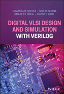
Example 5: Difference in types of always block.
Let’s take an example of always_type by writing a system Verilog code for Figure 11.1.
logic A_next, B_next, C_next;logic A_r, B_r, C_r;always_ff @(posedge clk)beginA_r ≤ A_next;B_r ≤ B_next;C_r ≤ C_next;endalways_combbeginB_next = A_r + 1;C_next = B_r + 1;end
11.4 $log2c() Function
A very interesting feature is present in SystemVerilog which proves to be very important as the binary number system is the base of any digital circuit. This feature is a new system function, ‘$log2c(),” which performs the same functionality as ⌈log 2 x⌉. This function is able to determine the required number of bits for the representation of any value.
For example, when designing a mod‐M counter, the required number of bits is determined by “log 2 M.” The code in SystemVerilog using this new feature will be:
module modcounter#(parameter M = 100) //mod‐M(input logic clock,output logic [$clog2(M)‐1:0] Q);logic [$clog2(M)‐1:0] present_state, next_state; //signal declarationalways_ff @(posedge clk) //registerpresent_state ≤ next_state;assign next_state = (present_state = (M‐1)) //next‐state logic? 0: present_state + 1;assign Q = present_state; //output logicendmodule
11.5 System-Verilog as a Verification Language
SystemVerilog is an object-oriented language incorporated with the benefits of object-oriented programming, inheritance, and polymorphism widely used in developing verification code by other high-level languages such as C++. These are very important features which make SystemVerilog language an HDVL (hardware description and verification language) but these are beyond the scope of the book.
Review Questions
Q1 Explain the difference between always_comb and always@(*).
Q2 Using enum datatype write a code to control traffic lights.
Q3 Design 512MB RAM using packed array and make it accessible using 2-dimentional ports.
Q4 Compare usage of packed and unpacked arrays in detail.
Q5 Compare Verilog and SystemVerilog in terms of available datatypes.
Multiple Choice Questions
Q1 The advantage of keyword “logic” as a data type is that it can be declared in place:
- wire
- reg
- both wire and reg
- None of the above
Q2 By using the facility of cast:
- upacked array can be converted in packed array
- packed array can be converted in unpacked array
- upacked array can be converted in packed array and vice versa
- None of the above
Q3 The keyword used in data-type for symbolic representation of data (values by names) is:
- Symb
- enum
- dname
- None of the above
Q4 The always block describing the circuit which contains registers is written as:
- always_comb
- always_latch
- always_ff
- None of the above
Q5 The value evaluated by $log2c(8) will be
- 2
- 3
- 4
- 6
Reference
- [1] IEEE. (2019). P1800 - Standard for SystemVerilog. https://standards.ieee.org/project/1800.html (accessed 22 June 2021).