
Floral Reflection. © Tim Meyer 2003.
Chapter 5 Overview
This chapter explores the process that digital capture systems use to convert the light exposing the sensor into a useable digital image. This sequence of steps includes charging the sensor, capturing light energy, moving the charge off the sensor, quantizing the analog signal, and defining the color for each pixel. How much fine detail can be captured is also discussed.
Electronic Sequencing
The lens projects light onto the sensor. Then an image is captured that can be viewed after digital processing. The sequence of steps is not as simple as it looks. The process begins with activation of the camera and ends when the image is written to memory. Turning the camera on does not necessarily prepare the sensor to take pictures. In most cases, the power switch only starts the processor that controls the camera. As with many other electronics, the power switch activates and checks the system’s operations and while preparing the camera. It is not until the camera control unit instructs the system to ready the chip that the sensor will be prepared to accept the light.
Before the image can be captured, several activities take place. Most important among these are metering for exposure and charging the sensor. Because the sensor is made of photodiodes, as are light meters, measuring the light can be done with the sensors. Other functions such as white balance can be accomplished with more advanced systems. Once the exposure is set, the sensor must be prepared to capture light. In order to calculate light values, the sensor must have a uniform charge on all sites. Without this uniformity, it would not be possible to assess the amount and variation of the light striking the individual sites. The camera accomplishes preparation of the sensor by applying an even positive charge to the gates of the sensor. In some cameras, the sensor’s gates do not charge until the shutter release button is depressed. If the sensor is charged after the shutter release button is pressed, a delay between the time the button is pushed and the time the picture is taken may result. When the system is positively charged and grounded, the positive charges that were applied to the gates migrate toward the ground, thus giving the positive charge to the potential wells.

Figure 5-1 A positive charge is applied to the gate. Because the system is grounded, the charge on the gate is drawn toward the ground, moving the positive charge to the potential well.
At this point the shutter is activated. The shutter may be an optical shutter or an electronic shutter function built into the sensor. Electronic shutters are timing sequences created by accumulating charges on the sensors and then clearing the charge at the end of the exposure time. Electronic shuttering can be part of the interline architecture without compromising the fill factor. Another type of electronic shuttering known as rolling shuttering advances sensitivity across the sensor. Rolling shuttering requires more functionality and does impact the fill factor.
The electromagnetic energy of the light enters the system, exposes the sensor, and becomes a negative charge at the gates of the sensor. Opposite charges attract; thus the positively charged wells provide a pulling strength that attracts a negative charge. The negative charge created by the light is drawn into the depletion layer of the sensor by the positively charged wells. Depending on design, wells can capture over 300,000 electrons. This is the well capacity. The well capacity in comparison to the noise level will become the range of light intensities that can be captured. The charge continues to accumulate until the exposure is stopped or the maximum well capacity is reached.

Figure 5-2 The photons of the light acting as electrons are attracted to the positively charged well, where they are captured.
If the capacity is reached and energy continues to affect the site, the charge can spill over to neighboring sites. This overexposure effect is known as blooming. Blooming occurs when the gate has accepted as much energy as the photodiode can record. At this point, the gate is saturated. If the site is saturated, sites around the saturated site can absorb the excess charge. Anti-blooming operations, however, bleed off the excess charge so it cannot be absorbed by neighboring sites.
Once the light has been captured, several processes occur in order to build the image. The first step is to remove the signals from the active sites. This is normally done in two ways. First, the signal is moved to another light-protected area of the chip that is designed to hold the signal for only a short time. As described in Chapter 2, various architectures of sensors transfer signals from the active sites to these other areas of the chip in frame, interline, or frame interline patterns. The other method of removing the signal is direct linear transfer. As the signal exits the sensor, it moves to the shift register pattern. The shift register is a short-term storage while preserving the ordering required for further processing. While the light can be quite strong, the signal itself will have to be amplified.
Because a complementary metal oxide semiconductor (CMOS) has transistors on the chip, these can be used to amplify the signal before it is moved from the sensor. Some designs amplify the signal as the signal is removed from an interline transfer or as it exits the chip. It is a misconception that digital capture collects images digitally. The light falling on the sensor is a continuous form of energy—analog. These analog quantities of light are captured within the exposure range of the sensor, and the signal coming from the sensor is an analog signal.

Chris & Sam. © Jim Wildeman.
Electronic Processing of Digital Imaging
In the charge-coupled device (CCD), the basic process is linear. The energy captured in the well is moved off the site at the end of the row. When the energy is removed, a draw is created that promotes migration of the energy from the adjacent site to the newly emptied site. This process is a chain reaction—as a site is emptied, the energy from the adjacent site in that row migrates into the vacant space, and the process continues until the row is emptied of all its charges. Because the CMOS is manufactured with transistors as part of the chip, the charge can be taken off as a CCD or it can be programmed to take the charges off in nonlinear ways.
Two problems that might be encountered with CCDs should be mentioned here. The first is smearing, which occurs when light strikes the sensor as the charge is being transferred from the well. In the final image, this will look like streaks emanating from bright areas of the picture. The second transfer problem, fading and weakening of the signal, is due to a loss of efficiency during the charge transfer.
Regardless of how the captured light is moved from the active photodiodes, the signal that is sent from the chip is not digital, as noted previously. The light is captured as analog energy and is exported from the sensor as an analog signal. In order to produce the image digitally, the analog signal must be converted via a quantization process carried out by an analog-to-digital converter (ADC). Further short-term storage can be provided by buffers. Image buffers are short-term memory devices that allow for rapid sequential imaging. The signal is then sent to the ADC for quantization.
Analog-to-digital converter (ADC) Provides a link between the analog world of light capture and the digital world of signal processing by analyzing the incoming analog signal and changing it to digital code.
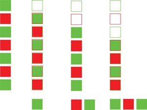
Figure 5-3 Sequencing removes the charges from a charge-coupled device (CCD). One charge is removed electronically, leaving a charge gap. The neighboring site then migrates to fill the gap, and all sequential sites transfer its charge. This continues until the row of sites has been emptied of all its charges.
Quantization
The process of quantization involves reading the strength of the signal generated by the capture of light in the potential wells and converting it to a digital number. A simplified view of the mathematics is to imagine a wave generated by the sensor being drawn on graph paper with x and y axes. The conversion proceeds by recording values of points along the wave on the graph as binary numbers indicating each point’s height. The binary number gives value to the strength of the light striking the sensor. Quantization creates the digital numbers that the rest of the system will work with in the camera, computer, or printer.
Quantization Process of converting a signal from a set of continuous linear values to a set of related unit values.

Figure 5-4 Quantization measures the value of energy and converts the measurement into a number value.
The binary system builds numbers based on the power of two. The bit, the basic unit of the system, is 0 or 1. The 0 indicates no electronic value, or Off, and the 1 indicates a charge value, or On. By using a series of 0’s and 1’s, any real number can be constructed; however, for digital imaging the numbers get quite large and normally units of bytes (8 bits), kilobytes (KB, 1000 bytes), megabytes (MB, 1000 KB), and gigabytes (GB, 1000 MB) are used. The range of signal strength that can be converted to these digital numbers is known as bit depth, which most commonly ranges from 8 (28 = 256 levels) to 12 (212 = 4096 levels) bits per channel. The bit depth represents the light intensity or grayscale value as captured. Some systems record and/or report out 16-bit channels, but these are interpolated for photographic output purposes.
The ADC calculates the energy value at each pixel location. As captured, the data do not show the scene’s color but is captured in the filtered color of each photodiode. All the data from the sensor are transmitted in a raw (uninterpolated) output form; however, most systems are programmed to interpolate the color through the array processor. The array processor is each manufacturer’s proprietary process for generating and balancing the color image.
Array processor Calculates and establishes the colors for each pixel within the digital camera system.

Waves, Death Valley. © Terry Abrams.
Factors Affecting Exposure
Other aspects related to exposure when using a digital capture device include the effective speed (ISO), the sensor’s electromagnetic spectrum (EMS), sensitivity, noise, and dynamic range. Like many electronic systems, the sensitivity of the chips in many situations can be adjusted. By changing the electronic gain for the chip, the sensor can vary its sensitivity, thus changing its effective ISO. With adjustable ISO, the sensors can function to address the varying conditions encountered by photographers. Commonly, sensors have effective ISOs from 25 to 400. Higher ISOs produce images of lower image quality primarily because of increased noise.
ISO (International Standards Organization) Not just an acronym; instead, the name derives from the Greek word iso, which means “equal.” Photographers are most familiar with ISO ratings of film speeds which are used for sensors.
The light that is captured by the sensor is only part of the electromagnetic energy spectrum. Because of the absorption characteristics of the silicon, indium tin oxide (ITO), or other materials used to construct the photodiodes, their sensitivity differs from that of the human eye or film. Sensors are sensitive to longer wavelengths of the visible spectrum and extend into the near infrared portion of the EMS. Unwanted infrared exposure is eliminated using either chromatic filtration over the sensor or hot mirror filtration. In hot mirror filtration, the longer infrared wavelengths are reflected into a heat sink that absorbs this portion of the EMS. While the sensors far exceed human perception, extending beyond red into the infrared, sensor sensitivity drops off sharply at the blue/violet end of the spectrum. This makes digital capture of short wavelengths less effective than for other areas of the visible spectrum.

Figure 5-5 Comparison of vision and sensor sensitivity.
A major problem with sensors is that they generate noise because the system is electronic. As electrons move about the sensor, they can stray, affect a site, and be recorded as captured light. While noise cannot be avoided, two major causes of increases in the noise level are long exposure and heat. Heat energy is part of the EMS, and some of this energy can be released as noise.
Three types of noise are common with electronic imaging. Signal noise is inherent to all imaging and in many situations is necessary to output tones without banding. Without some noise, a uniform tone will create a perceptual edge at its boundary. Sensors have a basic pattern of noise that is systemic. Software applications to the file or using multiple and eliminating exposures can filter system noise. A second type of noise is non-exposure noise often referred to as dark noise because it can be seen more readily in darker areas of an image. Last, noise is caused by the electronics of the capture device and its reaction to environmental situations, as well as the capture of extraneous electrons by the sensor’s sites. Regardless of the type of noise, when the signal-to-noise ratio is low, the captured level of light is not significantly greater than the noise level, and the image loses quality because of the presence of noise.
Banding Occurs when an image has too little color variation; colors tend to become flat and have distinct lines at their borders. Often caused by a limited color space or effects of compression and decompression of the image file.
One method that some manufacturers use to reduce the effect of noise in an image is known as dark frame reduction, which creates a mask based on the dark noise present in a frame exposed to black. When an exposure is made that is prone to noise, such as a time exposure, a software application is used to create a second exposure with no light reaching the sensor. This dark noise pattern mask can then be used to reduce the effect of the noise in the picture.

Figure 5-6 and Figure 5-7 Image noise signal-to-noise ratio.
High-level sensors are cooled to reduce the noise level. The least expensive option is to use a fan to move air across the sensor to reduce the sensor temperature slightly. More effective are refrigerated sensors that have microrefrigeration units to cool the sensor. The most effective option, used for scientific applications, is a coolant additive system, which uses cold materials, such as liquid nitrogen, to reduce the temperature of the sensor. To varying amounts, these methods of cooling reduce noise and thus increase the dynamic range. The construction and operation of available sensors varies, and CCD sensors tend to have less noise than CMOSs.
In short, sensors gather light. The tonal range that a device can capture is known as the dynamic range, which can be defined in different way by the various manufacturers. Most commonly, the decibel (dB) rating and stop range are used. The decibel rating uses a logarithmic ratio between the noise level and the well potential. Sensors vary greatly, but many achieve a rating of 80 dB with an ability to gather a 16,000: 1 ratio of light gathering to noise level. The stop rating is more familiar to photographers. Some manufacturers rate their sensors at 16 stops or more. Some digital systems have the ability to resample for intensity and stretch the tonal separation, effectively expanding the apparent dynamic range. With the expanded dynamic range of digital sensors, it is now possible to capture light that was beyond the reach of film, approaching the entire range of light we can see.
Decibel (dB) Unit of measure expressing the relative difference in power or intensity. It is commonly used to compare two acoustic or electric signals and is equal to ten times the common logarithm of the ratio of the two levels.
Dynamic range Measure of the tonal range of light, from brightest to darkest, that an imaging device can capture.
The physical size of the pixel (photosite’s gate) also affects the captured dynamic range. Larger pixels will gather more light information translating into a greater dynamic range. This creates a trade-off between capturing fine detail and light value information. In some systems software is used to mediate the loss of dynamic range captured by small sized pixels. The Fuji® SR sensor uses two photodiodes with different sensitivities at each pixel location to expand the captured dynamic range. In this arrangement, a small portion of the site is less sensitive and thus is used to capture the bright light exposing the sensor. The larger portion of the site is more sensitive to light, thus capturing the lower level light.
Software can be used to reduce image noise. Reproducing the effect of the noise and then removing it to the extent possible reduces the amount of noise in the image. The most common way of doing this is to replicate the exposure time without allowing light to strike the sensor, and a pattern created by only the noise is recorded. Based on this pattern, a masking filter can be created to reduce the noise, because the noise for any given exposure time is quantifiable and reproducible.
Most important for an area array is the generating of a color image. This requires filtration, as sensors do not respond differentially to varying wavelengths (colors), but only to the energy strength of the light within the sensor’s sensitivity range. Without using color filters, a sensor will act like panchromatic film acquiring only a grayscale image. Sensors use a matrix of red, green, and blue filters over the photosites that when processed interpolate the color for each pixel. If or when the file is not interpolated, a RAW file is obtained. This means that each pixel will be a light value for the filter color over the site. The RAW file will be discussed further in Chapter 8.

Figure 5-8 Simplified color filter matrix.
In a simplified model of the interpolation of the color, assume that a sensor has only four sites: two green, one red, and one blue. Because colors can be defined in terms of mixtures of red, green, and blue, when we capture them with such a matrix we have all the information needed to generate estimations of the colors within a scene. While a color can be made up of more than three 8-bit channels, most images can be handled in this form, and this format will be used for our discussion here. In a 24-bit color pallet each-channel at each pixel will have 1 byte, or 8 bits (28 = 256), of information regarding light levels for red, green, and blue; thus, the file of the image contains 3 bytes of color information for each pixel. A 4-megapixel sensor creates 12-megabyte files in an interpolated file format. In this 8-bit-perchannel arrangement, black or no light will be recorded as 0, and white will be recorded as 255. With color filtration, each channel of red, green, and blue will have levels ranging from 0 to 255. Using 8 bits of illumination information for each of the three primary color channels (red, green, and blue, or RGB), 16,777,216 colors are possible. These colors are generated through an algorithm that uses information from more than one site.
Algorithm Set of mathematical methods, rules, and/or procedures used to solve a problem.
While the algorithm is not as simple as the example used here, this explanation gives some idea of the process required. For some sensors, an area array processor handles this conversion. In our example, the values from each of the four sites on the sensor (G–R–G–B) are read and mixed. The algorithm used here sums the values of the two green sites and then divides that figure in half. The red and blue values are used as quantized. This provides a combination of the three colors (red, green, and blue) at an interpolated pixel. At this point, there are as many pixels as sites on the sensor.
Fall Colors. © Ike Lea, Lansing Community College.
A major problem with interpolation using the above Bayer array is that an assumption is made that the light exposing through any of the three filters must only be passing the color of the filter through. These filters are not pure and allow some other colors to expose the site. If the recorded light is from a uniform color area, then the interpolation should be valid, but this is seldom the case. For example, even assuming that no red light strikes the red-filtered site and that the red filter will pass through some blue light, then the photosite will absorb some energy from blue light. Therefore, it cannot be conclusively said that the blue light does not affect the red sites. In addition to the small amount of color inaccuracy there is the potential for moiré patterns when photographing fine-grid patterns. As discussed in Chapter 3, the Foveon X3® technology stacks the sensors, and while this reduces moiré it is necessary to interpolate some of the color because of crossover exposure on upper sensor areas.

Figure 5-9 Interpolation of a fleshtone color involves interpolating the two green filtered sensors (125 and 129), giving a value of 127. This value is used along with the red value (230) and the blue value (127) to form a pixel value of 230: 127: 127.

Figure 5-10 and Figure 5-11 The first picture shows a detail of an approximate captured image (a RAW file). The second picture shows the effect of the color interpolation as seen in the final image.
A 24-bit color pallet is not the only file structure available for color in files. An older file type that still has some use on the World Wide Web is an 8-bit color pallet format that provides 256 separate colors, with no other mixtures possible. Even though there are only 256 colors, they can be chosen as an “adaptive pallet” that allows users to select colors to fit the image in the file. Also available are 48-bit files for both capture and saving. These files have 16 bits (2 bytes) per channel, or 65,000 light values per channel. The human perceptual system can only see about 10 million colors, so these bit depths of 8 and 16 bits per channel calculate many more colors than can be recognized by a human observer. It must be noted, however, that some of the colors that can be seen by a normal human cannot be calculated mathematically.
Sampling and Detail
Two components of an image determine its quality: (1) color, which is defined by the color array processor as just explained, and (2) sampling rate. Sampling determines how fine the image divisions are; in other words, it is the ability of the sensor and system to resolve detail. The resolution of a digital image is discussed in terms of pixels per inch (PPI).
Detail in a picture is more critical to a successful image than any other single quality. Resolution is a measure of how well a photographic system can handle detail,or resolve the separation of fine lines. Both physical measurement and perceptual judgment can determine resolution. The sampling rate must be twice as fine as the detail to be captured in the image; a principle known as the Nyquest limit states that to image a detail it must be projected on the sensor twice the size of the pixel. From the perceptual point, the resolution must meet the needs of the photographer; that is, the output of the process is acceptable to the photographer.

Figure 5-12 High sampling rate; moderate sampling rate; low sampling rate.
Under-sampling Occurs when the capture of an image uses fewer sites than the number required to accurately capture a detail.
Aliasing Occurs when the shape or attitude of a detail in an image changes faster than an acceptable sampling rate and jagged or step-like artifacts form along the contour of the detail.
The most common artifact resulting from under-sampling of an image is aliasing, which occurs when the resolution is not fine enough to adequately sample a smooth and rapid change in the image, with the result that the pixels making up the edge of the detail are quite apparent. This situation is often referred to as aliasing or the jaggies. This problem is sometimes addressed by using anti-aliasing software that blends tonal variations into the aliased edge. This softens the step-like look of the aliased detail.
Some systems utilize software to make larger file sizes. Through a combination of software applications, the output file can be modified to resemble one made with a sensor with more pixels. The software increases the size of the image and then applies edge enhancement techniques to provide anti-aliasing and edge contrast. While the resulting image is larger, no more detail can be revealed. If the detail is not captured at the time of exposure, it is not in the image.

Figure 5-13 At high enough magnification, a digital image shows aliasing.
Software can also be used to reduce the output size. A photographer might want to make small files that can be exported rapidly or moved quickly, have lower final use requirements, or do not require high sampling rates. In these cases, many cameras allow grouping of pixels to resample the image to a smaller file size.

Telluride, Wildcat Studios, Stacy Smith.
Often overlooked is how sampling affects color. Because the capture device determines the number of distinct divisions in the image, the pixels, small differences in color are missed with lower level sampling. In order to maximize the color definition in an image, then, the sampling rate must be maximized.
Our discussion of resolution should include a comparison of a digital image to a film image. Because silver halide crystals are one-fourth the size of the smallest commonly used sensor site, film has the potential to gather more information based on surface area. A 35-mm film frame has about 100 million crystals in its emulsion that generate about 14 to 17 million pieces of image information. Taking into consideration the Nyquest limit, a digital sensor would have to have twice the number of sites to gain the same detail as film; however, with digital imaging the critical issue is the number of pixels in the final image application. A comparison of digital to film will be discussed further in the last chapter.
Types of Digital Images
Within the digital format two types of digital images are possible. The least-used method of digital imaging is the vector graphic. Vector graphic images are the type used in computer animation and are made up of small, interconnected lines that create a wire frame, which defines the object. This wire frame is then texture mapped with digital detail to allow for a solid image. There are very few specialized cameras that can capture and create vector graphic images. The vast majority of digital images are bit maps, also called raster graphics. Where the vector graphic can be used to create either a two- or three-dimensional object, the bit map produces only a twodimensional image. In a bit map, pixels are located within a grid. The bit map is a direct transformation of the site structure on the sensor. When the file is exported from the on-camera processing unit, it is formed into a bit-map image. The points on the bit map are called pixels (picture elements). Each pixel has color information in the form of a digital number defining its red, green, and blue values. The values recorded for each pixel are the interpolated or combined light values for the red, green, and blue values for that pixel.
One N. Wacker Drive. Craig Duggan © Hedrich-Blessing.
Summary
- Digital capture requires sequencing activities. In order for the sensor to acquire the light accurately, a consistent positive charge must be applied to the sensor.
- The image light is captured in analog form, after which it must be removed from the sensor and then converted into digital values through the process of quantization in the ADC.
- The sensitivity of the sensor is defined by the part of the electromagnetic spectrum and how much light the sensor can capture. The lower level of capture is the noise level.
- Because the sensor captures the strength of light, not different colors, to capture color we must interpolate either filtered light or stacked, separated light.
- Sampling is the way we define the way we capture detail.
- While some digital systems use vector graphic images, the majority of images used in digital imaging are bit-map files.
Algorithm Set of mathematical methods, rules, and/or procedures used to solve a problem.
Aliasing Occurs when the shape or attitude of a detail in an image changes faster than an acceptable sampling rate and jagged or step-like artifacts form along the contour of the detail.
Analog-to-digital converter (ADC) Provides a link between the analog world of light capture and the digital world of signal processing by analyzing the incoming analog signal and changing it to digital code.
Array processor Calculates and establishes the colors for each pixel within the digital camera system.
Banding Occurs when an image has too little color variation; colors tend to become flat and have distinct lines at their borders. Often caused by a limited color space or effects of compression and decompression of the image file.
Decibel (dB) Unit of measure expressing the relative difference in power or intensity. It is commonly used to compare two acoustic or electric signals and is equal to ten times the common logarithm of the ratio of the two levels.
Dynamic range Measure of the tonal range of light, from brightest to darkest, that an imaging device can capture.
ISO (International Standards Organization) Not just an acronym; instead, the name derives from the Greek word iso, which means “equal.” Photographers are most familiar with ISO ratings of film speeds which are used for sensors.
Quantization Process of converting a signal from a set of continuous linear values to a set of related unit values.
Under-sampling Occurs when the capture of an image uses fewer sites than the number required to accurately capture a detail.