
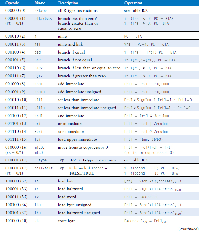
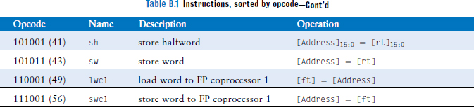
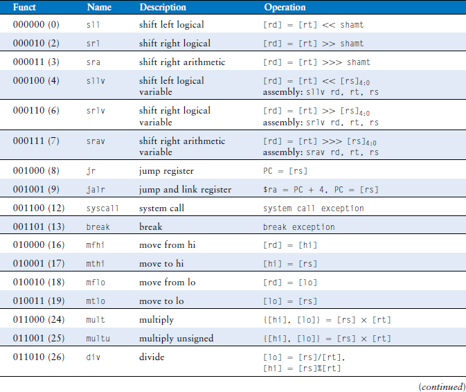
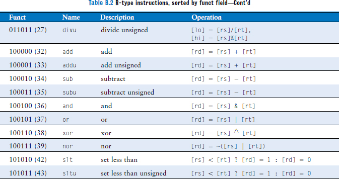
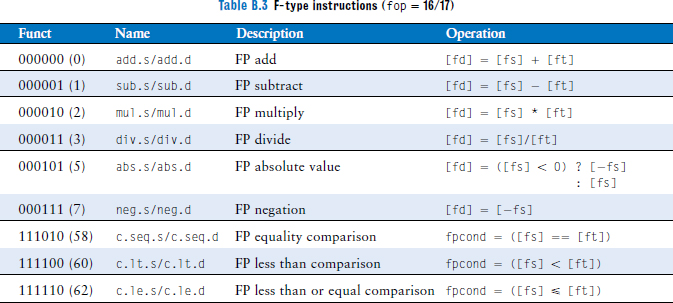
This appendix summarizes MIPS instructions used in this book. Tables B.1–B.3 define the opcode and funct fields for each instruction, along with a short description of what the instruction does. The following notations are used:
[reg]: |
contents of the register | |
imm: |
16-bit immediate field of the I-type instruction | |
addr: |
26-bit address field of the J-type instruction | |
SignImm: |
sign-extended immediate | |
= {{16{imm[15]}}, imm} |
||
ZeroImm: |
zero-extended immediate | |
= {16’b0, imm} |
||
Address: |
[rs] + SignImm |
|
[Address]: |
contents of memory location Address |
|
BTA: |
branch target address1 | |
= PC + 4 + (SignImm << 2) |
||
JTA: |
jump target address | |
= {(PC + 4)[31:28], addr, 2’b0} |
1 The SPIM simulator has no branch delay slot, so BTA is PC + (SignImm << 2). Thus, if you use the SPIM assembler to create machine code for a real MIPS processor, you must decrement the immediate field by 1 to compensate.
..................Content has been hidden....................
You can't read the all page of ebook, please click here login for view all page.