Edison: Enabling Extreme Scale Science at NERSC
NERSC
3.1 Edison Supercomputer—NERSC-7
3.1.1 User Base and Science Areas
3.3.3.3 Hardware Supervisory System
3.3.4.2 Cray Sonexion 1600 Hardware
3.3.4.4 Data Management Platform and Login Nodes
3.4.1 Computational Research and Theory Facility
3.4.2 Cray XC30 Cooling Design
3.6 Early Application Results on Edison
3.6.2 Large-Scale Structure of the Universe
3.6.3 Graphene and Carbon Nanotubes
3.6.4 Better Combustion for New Fuels
3.7 Exascale Computing and the Future of NERSC
3.7.1 NERSC-8 as a Pre-Exascale System
3.7.1.2 Collaboration with ACES
The National Energy Research Scientific Computing Center (NERSC) at Lawrence Berkeley National Laboratory (Berkeley Lab) is the primary scientific production computing facility for the Department of Energy’s (DOE) Office of Science (SC). With 5,000 users from universities, national laboratories, and industry, NERSC supports the largest and most diverse research community of any computing facility within the DOE complex. NERSC provides large-scale, state-of-the-art computing, storage, and networking for DOE’s unclassified research programs in high energy physics, biological and environmental sciences, basic energy sciences, nuclear physics, fusion energy sciences, mathematics, and computational and computer science.
NERSC – originally called the Controlled Thermonuclear Research Computer Center – was founded in 1974 to support the fusion energy research community, the first time such a powerful computing resource was used for unclassified scientific computing. Located at Lawrence Livermore National Laboratory from 1974 to 1996, the center was renamed the National Magnetic Fusion Energy Computing Center in 1976, and in 1983 began providing a fraction of its computing cycles to other research areas.
To reflect its increasingly broad scientific mission, the Center was christened the National Energy Research Supercomputer Center in 1990. The facility moved to Berkeley Lab in 1996 and, while keeping the acronym NERSC, was renamed the National Energy Research Scientific Computing Center. NERSC is currently housed in Berkeley Lab’s Oakland Scientific Facility, but will relocate to the new Computational Research and Theory facility on Berkeley Lab’s main campus in 2015.
Over the years, NERSC has installed and operated many of the world’s fastest supercomputers. In fact, NERSC’s history is a reflection of the evolution of high-performance computing (HPC) over the last four decades. In 1974, the Center began operation with a borrowed Control Data Corporation (CDC) 6600 computer. In 1975, a CDC 7600 replaced the 6600, but the new machine was rapidly filled to capacity, and for a while NERSC had to purchase additional 7600 time from Berkeley Lab.
The Center acquired a Cray-1 in 1978 and soon became known as an innovator in the management and operation of supercomputers. The world’s first Cray-2, a four-processor system, was installed at the Center in 1985. In 1992, with its user base growing steadily, NERSC added Cray’s newest supercomputer, the Y-MP C90 – the first C90 to be installed in the U.S. at a non-classified customer site. In 1997, the facility deployed a Cray T3E-900 supercomputer and named it MCurie in honor of Marie Curie, a physicist who was the first woman to win a Nobel Prize. MCurie was followed two years later by Seaborg, an IBM RS/6000 SP system named for Berkeley Lab Nobel Laureate Glenn Seaborg.
In 2003, NERSC put its first 10 teraflops per second IBM supercomputer – the Seaborg II – into service, providing researchers with the most powerful computer for unclassified research in the U.S. at the time. From 2005 to 2009, NERSC further expanded its supercomputing resources to include DaVinci, an SGI Altix system; Jacquard, a Linux computing cluster; Bassi, an IBM p575; and Franklin, a Cray XT4 that was one of NERSC’s most prolific supercomputers before being retired in 2012. And in 2010, NERSC broke the quadrillions-of-calculations-per-second mark with its Hopper system, a Cray XE6 named for pioneering computing scientist Grace Murray Hopper.
NERSC also has a history of collaborating with users to migrate their codes to next-generation architectures. These code changes are often evolutionary, but sometimes significant modifications are needed. During the late 1990s, NERSC worked very closely with its users to successfully transition their codes to massively parallel architectures. This was a daunting task due to the large number of teams computing at NERSC and the complexity of the changes that were required. A similar transition is now under way with the emergence of manycore processors. NERSC is launching an application readiness effort aimed at preparing our users for energy-efficient processors that will be used in NERSC systems going forward.
A paradigm shift for NERSC has been the growing importance of data-intensive computing. Almost every month more than a petabyte of data is transferred to the Center from experimental facilities around the world. The Center currently deploys data-intensive systems to analyze this deluge of data. Many generations of the Parallel Distributed Systems Facility (PDSF) at NERSC have served the high energy physics and nuclear physics communities for over a decade. In 2010, NERSC collaborated with the Joint Genome Institute to deploy a data-intensive system, Genepool, for DOE’s genomics community. Several architectural features in NERSC’s next supercomputer – announced in May 2014 and named Cori for American scientist Gerty Cori – are aimed at further supporting this data-intensive workload. Cori will have a significant data partition that will contain latency optimized processors with more memory per core and will run a software stack aimed at data-intensive computing. Cori will also contain a layer of nonvolatile memory to accelerate I/O, which is often a bottleneck for these applications.
From its earliest days, NERSC’s mission has remained consistent: to accelerate the pace of scientific discovery by providing high-performance computing, information, data, and communications services to the DOE SC community. Today, typically over 300 users are logged into each of NERSC’s supercomputers during daytime hours, with tens or hundreds of jobs simultaneously active. Batch queues run continuously, with each system typically running at 95% or higher utilization. The NERSC workload reflects the variety of the research performed by its users, including many simulations that span a large fraction of NERSC’s supercomputers. In addition to capability calculations, high-throughput data analysis and massive datasets are becoming increasingly important at NERSC in support of SC experimental facilities.
3.1 Edison Supercomputer—NERSC-7
During 2009-2011, the DOE SC Advanced Scientific Computing Research (ASCR) office commissioned a series of workshops to characterize the computational resource requirements for current and future science programs [7, 8, 9, 10, 11, 12, 13, 14]. A careful analysis of these requirements demonstrated a critical mission need for an order-of-magnitude increase in high performance production computing platform capability by 2014 to address the computational needs of projects sponsored by SC Program Offices and avoid creating an unacceptable gap between needs and available computing resources.
As a result, NERSC initiated the NERSC-7 program, with a goal of procuring and installing a next-generation supercomputer that could meet this computing criteria and enable NERSC to continue to support the research activities of SC. Through NERSC-7, NERSC acquired the very first Cray XC30 system (serial #1) and named it Edison in honor of American inventor Thomas Alva Edison (Figure 3.1). The XC30 [1] is the first all-new Cray design since Red Storm, a supercomputer architecture designed for the DOE’s National Nuclear Security Administration Advanced Simulation and Computing Program, which was first deployed in 2005.

FIGURE 3.1: Edison, NERSC’s newest supercomputer, is a Cray XC30 with a peak performance of 2.57 petaflops/sec, 133,824 compute cores, 357 terabytes of memory, and 7.4 petabytes of disk.
Edison was the first Cray XC30 supercomputer, which was developed in part with the Defense Advanced Research Projects Agency’s (DARPA) High Productivity Computing Systems (HPCS) program. Run by the U.S. Department of Defense, DARPA formed the HPCS program to foster development of the next generation of high productivity computing systems for both national security and industrial user communities. Program goals were to develop more broadly applicable, easier-to-program, and failure-resistant high performance computing systems. The Cray XC30 system represents the last phase of the three-phase HPCS program, and the DARPA HPCS prototype became the first cabinet of Edison.
As part of the program, DARPA and its mission partners were to have up to 20 million hours of computing time on an XC30 for testing, evaluation, and machine characterization. In a collaboration with Cray and DARPA, NERSC hosted mission partners from DARPA, DOE, and universities. Forty-four mission partner users were integrated into the NERSC community of users, with full access to NERSC training, consulting, and other user benefits. To ensure the mission partners had adequate access to the machine for their runs, NERSC implemented a fair-share schedule on the pre-production Edison system to give DARPA its promised 25% share of the system until the 20 million hour usage level was reached. Mission partners concluded their testing when Edison went into production in January 2014.
With the addition of Edison, NERSC was able to retire Franklin (NERSC-5). Hopper will continue in operation through 2015. Having two systems available to users is a fundamental operational and procurement strategy at NERSC. (See Section 3.2.4.)
The Edison system has a peak performance of 2.57 petaflops/s, 133,824 compute cores, 357 terabytes of memory, and 7.4 petabytes of online disk storage with a peak I/O bandwidth of 168 GB/s (Table 3.1). To enable this performance, Edison features a large number of high-performance compute nodes and a high-bandwidth, low-latency inter-node communications network that offers very high levels of sustained performance on real user codes. It incorporates Intel Xeon E5–2695 v2 “Ivy Bridge” processors and the next-generation Aries interconnect, which uses a dragonfly topology instead of a torus.
Edison was designed to optimize data motion, which is a key bottleneck for many of our applications. Many applications are unable to take advantage of more floating point operations per second unless there is a commensurate increase in memory bandwidth. Consequently, we did not deploy accelerators in Edison, which would have increased its peak speed but provide little average payoff to our very broad and diverse application base. By electing to deploy Intel Ivy Bridge processors with 1866 Mhz memory, we were able to provide more than a 2X increase in performance per node compared with Hopper (the previous generation NERSC-6 system [2]). Some applications report as much as a 4X increase due to the much higher memory bandwidth.
TABLE 3.1: Edison hardware specifications.
System Type |
Cray XC30 |
CPU Type |
Intel Ivy Bridge |
CPU Speed (GHz) |
2.4 |
Compute Nodes |
5,576 |
Service Nodes |
118 |
SMP Size |
24 |
Total Compute Cores |
133,824 |
Flops/Core (Gflops/sec) |
19.2 |
Peak Performance (Tflops/sec) |
2569.4 |
Memory per Node |
64 GiB |
Aggregate Memory |
349 TiB |
Memory Speed |
1,866 |
Avg. Memory/Core |
2.67 GiB |
Memory Bandwidth per Socket (STREAM) |
105 GiB/s |
Node Interconnect |
Arles |
Scratch Disk |
7.56 PB (local) + 3.9 PB (global) |
Disk Bandwidth |
168 GB/s |
Avg. Power (KW) |
1,600 |
Edison also utilizes a novel water-cooling mechanism that can operate with much warmer water temperatures than earlier supercomputers. The Cray XC30’s hybrid water/air cooling system, transverse airflow, and high operating temperatures allow NERSC to use the moist, cool air that flows through the Golden Gate from the Pacific Ocean to help reduce cooling costs and increase energy efficiency. Using cooling towers only – without any mechanical refrigeration – Edison can be cooled for one-third the cost of earlier systems [6].
3.1.1 User Base and Science Areas
NERSC serves a broad range of science disciplines for the DOE SC and is the principal provider of HPC services to the six SC programs: Fusion Energy Sciences, High Energy Physics, Nuclear Physics, Basic Energy Sciences, Biological and Environmental Research, and Advanced Scientific Computing Research. Each year more than 5,000 researchers are working on 700 projects and running 600 different codes at NERSC across a broad range of disciplines [2], including:
• Solar energy: Understand the processes by which biological systems use solar energy, and design materials to efficiently convert solar energy to usable electricity or fuels.
• Energy-efficient lighting: Design highly efficient energy conversion processes for enhanced light emission in solid-state lighting devices.
• Energy storage: Design efficient and low-cost batteries and hydrogen storage devices.
• Fusion science: Understand and control instabilities that limit efficiency in fusion energy reactors.
• Fundamental particles and interactions: Supercomputer simulations are crucial to support DOE’s “targeted outcomes” involving new facilities and experiments in quantum chromodynamics, the theory of the nuclear force, and the unification of the forces of nature.
• Accelerator design and development: Design cost- and energy-efficient particle accelerators, both for exploring the fundamental nature of the universe as well as for biomedical diagnoses and treatment.
• Astrophysics: Support DOE efforts in unraveling the origins of the universe, the nature of dark energy and matter, and astrophysical production of exotic nuclei. Another notable outcome will be the design and validation of a new generation of world-class telescopes and satellite.
• Climate science: Develop methods to predict extreme events. Support policy makers by providing accurate and precise understanding of relationships between climate change and Earth’s ecosystems.
• Biology: Create predictive, systems-level understanding of complex biological systems in support of DOE missions in energy, the environment, and carbon sequestration. Understand how cells communicate, how proteins are created from DNA sequences, and how enzymes operate.
• Bioinformatics: Develop genome-scale microbial and plant system technologies for energy, the environment, and carbon sequestration.
• Materials science: Identify or design novel materials for energy capture, conversion, and storage; energy-efficient devices; carbon sequestration; bioremediation; desalination; radically faster computers; and information storage and communication devices.
• Computer science: Develop new high-efficiency, multi-physics simulation methods and codes to support research in combustion, porous media flow, astrophysics, cosmology, and engineering.
The number of NERSC science users has been growing almost 350 per year since 2008, and we expect this growth rate to continue. We have observed a usage trend in the past 10 years toward sciences with more potential for applied research applications, and we expect this trend to continue.

FIGURE 3.2: NERSC resource utilization by science area.
NERSC’s primary focus is maximizing the scientific productivity of its users. To achieve high productivity, we balance computing, storage, and networking resources at our center. In addition, we deploy flexible resources to meet the wide-ranging needs of our users. For the last four years, NERSC has been a net importer of data. About a petabyte of data is typically transferred to NERSC every month for storage, analysis, and sharing.
Allocations of NERSC computer time are made on a yearly basis. Eighty percent of the DOE time is allocated by program managers in the DOE SC program offices; applicants must be part of a research project funded by the DOE SC or show that their work meets the DOE mission. Ten percent of DOE time is allocated through the ASCR Leadership Computing Challenge program. The final 10% of DOE time is the NERSC Director’s reserve, allocated through the NERSC Initiative for Scientific Exploration program.
Figure 3.2 shows the allocation breakdown of NERSC supercomputing resources by science area.
NERSC has nearly four decades of experience acquiring some of the largest supercomputers in the world, and as a result has developed a rigorous approach to procuring systems that has been widely adopted in the DOE community and elsewhere.
As the primary provider of high performance scientific computing, storage, and services for the entire DOE SC, NERSC must support the mission of all six SC program offices as well as satisfy the operational needs of the scientists who use NERSC’s resources. To ensure that it can meet these needs, NERSC regularly gathers requirements from the DOE SC program offices, other key HPC or domain experts, leading scientists in each research area, and its 5,000+ users. Requirements from the user community are obtained through regular meetings with the NERSC Users Group (NUG), an annual User Survey, allocations requests, one-on-one conversations with users, participation at community conferences and meetings, and a series of Computing and Storage Requirements Reviews with each program office within the DOE SC.
The requirements reviews are key to NERSC’s strategy for gathering community requirements. This ongoing series of reviews, one for each program office, brings together DOE program managers, science leaders, and NERSC staff to derive future HPC needs for scientific communities. The results of the reviews include community requirements for computing, storage, and services five years in the future. Requirements for software and services are also captured in the review reports [14, 13, 11, 12, 10, 9, 8, 7]. Together these results help DOE and NERSC plan for future systems and HPC services.
In addition, NERSC holds regular monthly teleconferences with NUG and an annual face-to-face meeting with NUG where NERSC users are invited to discuss issues of interest or concern and make their needs known. NERSC users elect a 21-member Executive Committee (NUGEX) that plays an active role in making suggestions for improving NERSC systems, services, policies, and procedures (e.g., queue configurations). NUGEX members are given invitations to attend the requirements reviews in their area of research.
NERSC also collects satisfaction, importance, and usefulness scores on various systems and services via its annual User Survey. The survey responses help guide NERSC’s choices for future systems and services offerings. Another important vehicle for collecting requirements is the allocations application process. When applying to use NERSC resources, projects are required to give detailed descriptions of their codes, data requirements, and software needs for the coming year.
The primary criteria for a NERSC system is sustained performance on scientific applications, not peak performance [16]. The required level of performance is based on the requirements gathering process and on available budget.
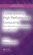
For Edison, as with several of its predecessors, NERSC used a suite of seven real applications carefully chosen to span important science areas and algorithmic methods (Table 3.2). A specific input deck is defined for each benchmark, and a flop count is measured on a reference system. Each bench-mark’s time to solution is measured to get a flop/sec rate, and then divided again by the number of compute elements to get a flop/sec/compute element rate. The geometric mean of flop/sec/compute element is calculated across all the benchmarks. The average rate per compute element is then multiplied by the number of compute elements to get the final Sustained System Performance (SSP) [17]. Thus, SSP is a function of both performance of each compute element and the number of compute elements; it represents the throughput of the system. This matches the NERSC workload well as user-run applications at all scales.
TABLE 3.2: Seven real applications chosen to test sustained performance NERSC supercomputers.
Note: Xs indicate algorithmic methods used by but not directly addressed for a particular science area.
Competing vendors must commit to an SSP target for a delivered system, and they must explain why they think they can meet that target. Vendors may be creative in meeting the target, balancing among such factors as processor and memory speed, core count, number of nodes, and compiler optimizations to determine the most competitive offering. The SSP target effectively establishes the “size” of the system for contractual purposes. If a delivered system with a particular number of processors, etc. does not meet the SSP requirement, the vendor is required to provide additional capacity to increase performance.
The SSP benchmark is updated for procurements of each successive generation of systems. This accounts for changes in computational methods and the introduction of new popular applications. However, the revised SSP is always calculated on earlier systems for comparison.
It is important to note that peak performance and microbenchmark performance (e.g., HPL or Stream) are considered at NERSC but are a minor factor in the center’s evaluation of the system choice. As previously noted, NERSC primarily focuses on SSP. Recent “Top 10” systems have employed GPUs to boost their peak performance, but such rates are difficult to achieve on most applications. As a result, the SSP for such systems as compared to the peak is a much lower ratio. NERSC chose not to list Edison on the Top 500 list because this increasing disparity between peak and sustained performance on real applications has rendered the ranking much less valuable.
Because of the wide difference in the characteristics of systems offered by vendors, it is difficult to make direct comparisons between their systems. A decision based solely on price may not represent the optimal choice to meet the needs of NERSC’s users. Instead, NERSC uses the “best value” process to make the selection [16]. Best value evaluates and compares non-price factors such as SSP, I/O performance, projected reliability, vendor reputation, and others, in addition to strict price. One of the most beneficial features of this approach is that it explicitly recognizes risk as a criteria, including technical schedule and business risks. Best value selection relies heavily on the judgment and experience of the buying team, as well as the various quantitative metrics available to describe machine performance.
As the production computing facility for the DOE SC, it is critical that NERSC be able to provide substantial computing capability at all times. For this reason, we have adopted a strategy of acquiring a new system approximately every three years. Since systems have an expected lifetime of five to six years, this means we always have two large systems in operation concurrently.
Our overlapping system strategy has many benefits. Maintenance on the systems can be staggered, keeping one in operation at all times. Since 2008, it has been easy for users to move applications between systems, enabling them to realize this benefit. In addition, site preparation, installation, and testing of a new system take approximately one year (or more) following decommissioning of its predecessor. During this integration period, users still have access to a system of substantial capability.
The three-year cycle roughly approximates the timeline for new product introductions. For example, in Intel’s tick-tock model, a complete cycle of new process technology (tick) and architecture (tock) takes roughly the same time period. Consequently, the newer system is closer to the state-of-the-art in performance and can address users’ largest and most demanding applications, while the older system takes on volume processing of smaller jobs. By comparison, if NERSC were to acquire a system every 5-6 years, the Center could afford to purchase a system of approximately twice the size at the time of acquisition. But Moore’s law (i.e., performance doubles every two years) would quickly render that system less performant than another newer system of half the price.
Edison is a highly scalable multiprocessor Cray XC30 that is built from multiple blades and connected by a flexible, high-bandwidth interconnect [15]. The system is packaged in 30 individually powered processing cabinets that provide an easily expandable and configurable environment. Each cabinet has three chassis; each chassis has 16 compute blades; each compute blade has four dual socket nodes.
Edison’s 5,576 compute nodes are powered by 12-core Intel Xeon E5–2695 v2 “Ivy Bridge” processors running at 2.4 GHz. Each node has two sockets, each of which contains an Ivy Bridge processor, so that each node has 24 cores [3]. Each core runs at 19.2 Gflops/core, which equals 460.8 Gflops/node and 2.39 Pflops/s for the entire system. The Cray XC30 is the first time Cray has used Intel Xeon processors in a high-end supercomputer.
All memory used in service blades and compute blades is based on DDR3 Dual Rank Registered DIMMs (dual in-line memory modules) configured as two ranks of x4-based DDR3 SDRAM devices. The memory supports the Intel extended ECC algorithm, which allows the nodes to detect and correct 1- to 4-bit internal data and data pin failures within one memory device and detect up to 8-bit internal data and data pin failures within two memory devices. The Cray XC30 is designed to recover from faults that are contained within a single memory device that do not impact other memory devices in the memory system. The dual-rank configuration permits rank interleaving to help reduce memory access latency and improve performance.
Edison integrates Cray’s HPC-optimized Aries interconnect to yield substantial improvements on all network performance metrics, including bandwidth, latency, and message rate. This network provides users with global access to all of the memory of parallel applications and supports demanding global communication patterns.
The Aries interconnect [1] uses a Dragonfly topology [15] for inter-node connections. This topology is a group of interconnected local routers connected to other similar router groups by high-speed global links. The groups are arranged such that data transfer from one group to another requires only one route through a global link.
This topology comprises circuit boards and copper and optical cables. Routers (represented by the Aries ASIC) are connected to other routers in the chassis via a backplane. Chassis are connected to form a two-cabinet group (a total of six chassis, three per cabinet) using copper cables. Network connections outside the two-cabinet group require a global link. The system uses optical cables for all global links. All two-cabinet groups are directly connected to each other with these cables.

FIGURE 3.3: The Dragonfly Network.
As shown in Figure 3.3, each router (Rx) in the Dragonfly Network is connected to four processor nodes (P). Sixteen blades, each with one router, are connected together at the chassis level by backplane links (Rank-1 Subtree). Six chassis are connected together to form the two-cabinet group by using copper cabling at the cabinet level (Rank-2 Subtree). Finally, the two-cabinet groups are connected to each other using optical cables for the global links (Rank-3 Subtree). A system may have as many as 482 cabinets.
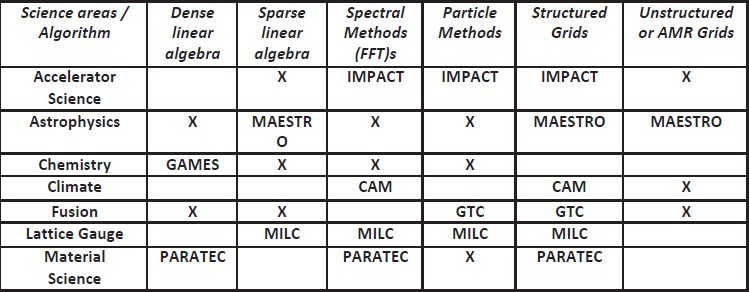
Within a chassis, the internal wiring of the backplane connects every Aries ASIC in the chassis to each other. As many as 16 Aries reside in each chassis (one per base board); there is one link between each ASIC. The interconnections of the chassis level ASICs require no cables. This set of interconnections is called the intra-chassis network (Figure 3.4).
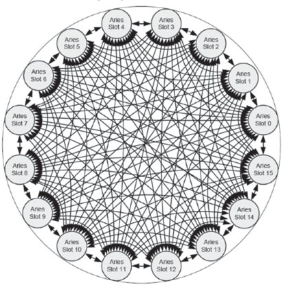
FIGURE 3.4: Intra-chassis connections (Rank-1).
Copper cables connect each chassis in the two-cabinet group. Each cable contains three links that comprise a total of 18 differential pair wires (36 total). Each cable connects a blade router to a blade router in another chassis, in the same slot location. For example, the router in Slot 1, Chassis 0, Cabinet 0 would be connected to the five blades in the Slot 1 position in the five other chassis (two in the same cabinet and three in the neighboring cabinet). Two cabinet groups are always fully connected, which requires 240 cables.
The Rank-3 network is used to interconnect two-cabinet groups. This level of the topology utilizes optical cables that are housed in integrated cable trays above the system cabinets.
The optical connection uses a 24-channel optical cable: 12 channels for transmit and 12 channels for receive. Each cable handles four links (six channels per link), two from each of two Aries ASICs. Up to five optical cables are associated with every pair of Aries ASICs, and a total of 40 optical connections are possible for each chassis. Thus a complete two-cabinet group has up to 240 optical connections.
The Rank-3 connections must form an all-to-all network between the two-cabinet groups. The width of these connections is variable and can be as few as 1 optical cable between two-cabinet groups and as many as INT(240/(N-1)), where N is the number of two-cabinet groups. For example, a system with 30 cabinets (or 15 two-cabinet groups) can utilize up to 17 optical cables (INT(240/(15-1)) between each pair of two-cabinet groups.
Since optical cables are the most expensive level of the interconnect, configurations are typically not fully populated in this dimension unless the application mix requires unusually high global bandwidth.
The Cascade processing cabinet has three individual chassis that support a backplane and up to 16 blades. Configurations of up to 16 compute blades or up to eight I/O blades and the remaining compute blades are supported. The I/O and compute blades are installed in the front of the cabinet, and the high-speed internal network connections (cables) are installed in the rear. In addition, each cabinet is equipped with a power distribution unit (PDU) and a cabinet controller for power control, cooling control, and Ethernet communication with the System Management Workstation.
The chassis blade slots are divided into a left-hand side and a right-hand side. Blades designed for one side cannot be plugged into the other. I/O blades are left-side only. Right-side compute blades plug into the right side of the chassis and left compute blades plug into the left I/O. The compute blades are connected by the Aries ASICs. Processors communicate with the Aries ASIC Network Interface Core over a PCI-e x16 link. The Aries ASIC routers are connected together with links to form the high-speed network that provides communication between nodes on the compute blades.
Compute blades are used only for user applications and have no direct external I/O connections. All I/O is routed through the Aries network. A compute blade is modular in nature and is composed of a base blade and two quad processor daughter cards (QPDCs) (Figure 3.5). The base blade has one Aries ASIC, a hardware supervisory system processor, connectors for the QPDCs, voltage regulator modules, connections for the copper interconnect cables, and a chassis backplane connector. Compute blades use QPDCs based on the Intel Socket R Xeon processor. Each QPDC contains two nodes, each composed of two processor chips and eight memory DIMMs. The QPDCs are designed to be upgradeable over time to accommodate new processing technologies as they become available. Compute blades are available with both a left- and right-hand version.
Service blades are used to provide operating system services and connectivity for the system. Functions include:
• Lustre LNET routing services FIGURE 3.5: Compute blade block diagram.

FIGURE 3.5: Compute blade block diagram.
• Connectivity to other file systems through the DVS facility
• Boot services and connectivity to the SMW and boot raid
• Connections to the login nodes
• Networking services
Service blades have one Aries ASIC, a hardware supervisory system processor, connectors for two node daughter cards, voltage regulator modules, connections for copper interconnect cables, and a chassis backplane connector (Figure 3.6). Service blades are based on the Sandy Bridge Xeon processor but contain only two nodes, each with one processor and four memory DIMMs. Each node is associated with two independent PCI-e busses (Gen3 x8), each of which is associated with a slot designed to hold various host bus adapters (HBAs). Hence a single service blade supports up to four PCI-e HBAs. Service blades are only available with a left-hand personality.
FIGURE 3.6: Service blade block diagram.
3.3.3.3 Hardware Supervisory System
The Hardware Supervisory System (HSS) is a cabinet- and blade-level subsystem that controls and monitors the basic functions and health of the system. HSS also plays an important role in system debugging and diagnosis of system faults. The major functions of HSS include:
• Monitor and control the cabinet’s power supplies and regulators
• Monitor and control the blade level power, including support of power management
• Monitor and control the cabinet and blade temperatures
• Conduct blade and node initialization sequences
• Provide monitoring and reporting services for nodes
• Support the In-Target Probe (ITP) test access port on the processors
• Report monitored device errors to the SMW
• Support processor memory dumps to the SMW through HSS network
• Support the diagnostic software for system analysis and diagnosis
The HSS consists of a SMW, cabinet controller (one for each cabinet), chassis host (one for each chassis), a blade controller (one for each blade), and various thermal and voltage sensors located throughout the cabinet (Figure 3.7). The cabinet controller, chassis host, and blade controllers are connected via a private Ethernet and a clocked serial sideband bus. In addition, the cabinet controller is connected to the SMW via a separate Ethernet network.
The processing cabinet includes the cabinet controller, PDU, and three chassis, with one chassis host each. Each chassis supports up to 16 compute or I/O blades. Each compute or I/O blade contains a blade controller for HSS control. Details are shown in Figure 3.8.
The cabinet controller is connected to the chassis host via Ethernet cables and sideband bus cables. Connection to the external Ethernet switch and SMW are via Ethernet cables only. The cabinet controller is directly connected to the cabinet controller backplane using standard backplane connectors. Connection of the cabinet controller to the blowers, rectifiers, and thermal sensors are through the environmental distribution board using various cables.
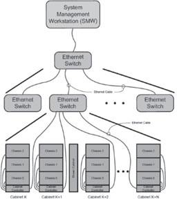
FIGURE 3.7: HSS cabinet level detail.
NERSC’s systems are configured with local, scratch storage for fast I/O for the jobs running on the system. They also use a shared file system that is available on all NERSC systems for home directories, site provided software, shared areas for each project, and a shared scratch file system used to facilitate data sharing between all systems at NERSC (including Edison, Hopper, and smaller throughput-oriented clusters) by avoiding the need to move data between file systems.
The Edison system has access to several different file systems that provide different levels of disk storage and I/O performance (Table 3.3).

FIGURE 3.8: Cabinet controller diagram.
TABLE 3.3: Edison’s file systems.
File System |
Home |
Local Scratch |
Global Scratch |
Project |
Environment Variable Definition |
$HOME |
$SCRATCH |
$GSCRATCH |
None. Must use/project/projectdirs/ |
Purpose |
• Global home file system shared with other NERSC systems. • All NERSC machines mount the same home directory. • GPFS file system. • Where users land when they log into the system. |
• Three Lustre file systems, with 7.5 PB of total storage disk space. • Local means the files are not accessible on other NERSC systems. |
• Large (3.9 PB) GPFS file system for temporary storage. • Currently mounted on all NERSC systems except PDSF. |
• GPFS global file system mounted on all NERSC systems. |
Default Quota |
• 40 GB • 1 million inodes |
• 10TB* • 10 million inodes |
• 20 TB • 2 million inodes |
• 1 TB • 1 million inodes |
Intended Purpose |
• Shell initializations • Storing source code • Compiling codes • Not intended for 10 intensive applications |
• Running production applications • I/O intensive jobs • Temporary storage of large files |
• Alternative file system to run production applications • Aid users whose workflow requires running on multiple platforms • Temporary storage of large files |
• Running production applications • Groups needing shared data access • Projects running on multiple NERSC machines |
Peak Performance |
Low,˜100 MB/sec |
168 GB/sec |
15 GB/sec |
40 GB/sec |
Purged? |
No |
Yes, files older than 12 weeks are purged. |
Yes, files older than 12 weeks are purged |
No |
Edison is configured with three local scratch file systems using the Lustre Parallel File System integrated into Cray Sonexion storage systems.
Two file systems provide 2.16 PB with a bandwidth of 37 GB/s, and one file system provides 3.24 PB file system with a bandwidth of 70 GB/s. The smaller file systems are used for user scratch directories and are assigned round robin the first time a user logs in. The third is provided on request for projects or users with a requirement for high-bandwidth applications.
Use of three file systems serves to improve metadata performance. At the time of Edison’s installation, a single Lustre file system was able to achieve only roughly 20 thousand metadata operations per second. This is a relatively low number and led to frequently long waits for listing directories or other file operations such as create or delete. Subdividing the workload into three separate file systems increased overall metadata throughput by a factor of three. Future Lustre versions are expected to implement a clustered metadata server, in which case NERSC may elect to consolidate the two smaller file systems.
Having multiple file systems also improves system availability. In the relative rare event that a file system is damaged and has to be taken down for maintenance, the remaining file systems can continue to serve users without taking the whole system down.
3.3.4.2 Cray Sonexion 1600 Hardware
The Cray Sonexion 1600 [4] is a complete hardware and software solution housed in network-ready 42U racks (Sonexion rack). Each Sonexion file system includes two redundant Metadata Management Units (MMUs), multiple Scalable Storage Units (SSUs) providing modular expansion of disk storage and bandwidth, and 14 Data Rate (FDR) InfiniBand switches to connect to the compute nodes via Lnet routers.
The two 2.16 PB file systems occupy two racks with 12 SSUs. The 3.24 PB file systems occupy three racks with 18 SSUs.
Scalable Storage Unit Hardware
All SSUs are configured identically. Each SSU includes two embedded server modules (ESM) running the Lustre OSS, Cray Sonexion Storage Manager (CSSM) middleware, and back-end services. Each SSU is configured with identical hardware and software including 84 shared drives with shared access by the two ESMs.
Each of the ESMs in an SSU serves simultaneously as active/active Lustre OSS servers, each providing a secondary failover service for its peer in the event of a failure. On failure, the surviving ESM will take over the OSTs of the failed ESM. Both ESMs in an SSU can access the disks as shared storage through a common 6 GB SAS midplane to all drives in the SSU and shares a redundant high-speed interconnect across the midplane for failover services. The ESM runs Linux and has its own dedicated processor, memory, and network and storage connectivity.
At the front of each 5U SSU are two drawers; each drawer has 42 drive bays that support 3.5 inch dual-ported NL-SAS drives housed within carriers. The rear of the SSU houses the ESMs, two redundant power supplies, and five hot-swappable fans.
Each SSU contains 80 dual-ported 3.5 inch 3 TB NL-SAS 7,200 RPM disk drives, providing 180 TB of usable capacity. The disks are configured as eight RAID 6 arrays, each with eight data disks and two parity disks. Each array is configured as a single volume and each volume is formatted as a single LDFS (ext4) file system that is assigned to function as a single Lustre OST. Under normal operation access to the eight OSTs in each SSU is split equally between the ESMs. Thus each ESM/OSS instance will own and provide access to four of the Lustre OSTs. Two dual-ported 3.5 inch 100 GB SSDs drives are configured as a shared RAID 1 array. This array is partitioned and used for the MDRAID write intent bitmaps (WIBs) and the OST/ldiskfs file system journals. The remaining two 3 TB NL-SAS disk drives are used as hot standby spares.
Metadata Management Unit Hardware
Each MMU is configured with identical hardware and software components. Each MMU includes one 2U server with four Intel Metadata Servers (MDS), active and passive Management Servers (MGS), and active and passive Mouse servers and a Metadata Target (MDT) array with 22 450 GB 2.5 inch 6 GB SAS drives and two 100 GB SAS SSDs configured as RAID 1 for metadata journaling. The 450 GB SAS drives are configured as RAID10. The MMU connects to the FDR InfiniBand rack switches and to the 1 GbE management network.
Each Sonexion file system is configured with two MDS servers for redundancy and memory capacity. The primary, active MDS manages the name and directories in the file system and provides the network request handling for the metadata (filenames, directories, permissions and file layout) that is stored on the MDT. There is one MDT per file system. The MDT is also available to the backup, passive MDS, so that if the primary/active MDS fails, the passive MDS can serve the MDT and make it available to clients. Such an occurrence is referred to as “MDS failover.”
Cray Sonexion 1600 Connection to Cray System Lustre Clients
Each Sonexion rack is connected to a host system via FDR InfiniBand cables and two director-class FDR InfiniBand switches to Lustre LNET router nodes in the system (Figure 3.9). The FDR InfiniBand switches are configured with enough ports to support the required Lustre file system bandwidth to the System and provide connectivity to the esLogin servers. Lustre client software on the Cray compute nodes are then able to communicate with the Cray Sonexion 1600 MMU and SSUs via the LNET routing capability. The Cray Sonexion 1600 supports communication with Lustre 1.8.6 and higher client versions.
Each file system requires two LNET routers to connect from the compute system to the MMU. SSUs are always deployed in groups of three, and require 4 LNET routers. Thus, there is a 2:1 ratio of LNETs to MMUs and 4:3 for SSUs.
Cray Sonexion Software
Edison utilizes the Cray Sonexion System Manager (CSSM), the management software used for installation, configuration, and baseline testing in the factory and management and monitoring at the customer’s site. CSSM features a graphical user interface (GUI) that provides a unified system management view, presenting all necessary information from the various sources on the platform including hardware, Lustre, and the storage. The GUI is accessible through a direct connection between the NERSC designated network and the Management Server (MGS).
Each Sonexion file system is configured with an active and a passive MGS to run CSSM and store information for all the resources in the file system. The Lustre MDS and OSS servers contact the MGS to post this information, and the Lustre clients interact with the MGS to discover location and configuration information for the file system components. Within a Sonexion 1600 the MGS runs in an active-passive configuration on a pair of server nodes that are connected to shared storage. This shared storage is referred to as the Management Target (MGT) that is provisioned as a discrete storage volume, dedicated for use by the MGT. The MGT and the underlying file system are hosted on a dedicated RAID 1 volume. In the event the active MGS fails, the failover process ensures that the passive MGS is activated, taking control of the MGT and all MGS functions.
Each Sonexion rack provides a dedicated local network on a 1 GbE switch that is used for configuration management and health monitoring of all components in the Cray Sonexion. The management network is private and not used for data I/O in the cluster. This network is also used for IPMI traffic to the MMU’s MDSs and the SSU’s OSSs, enabling them to be power-cycled by the CSSM.

FIGURE 3.9: Logical Cray Cascade LNET routing.
Software and firmware upgrades across an entire Cray Sonexion system are executed through CSSM. CSSM interacts with the enclosure firmware in the SSUs and MMU for each file system to provide the following:
• Failover and failback of primary and secondary I/O modules
• Thermal monitoring and automatic fan speed control
• Drive power control
• Drive fault/identity LEDs
• I/O controller fault/identity LEDs
• Enclosure LEDs and audible alarm control
• Device presence detection
• Power supply monitoring via PSMI
• Communications bus fault detection
• Data and fault logging
CSSM monitors and manages the entire Sonexion storage system and will provide administrative control to the Lustre file system and nodes. In addition to the GUI, CSSM supports the administrative functions to be run from a command line interface (CLI) using a terminal session.
The NERSC global file system (NGF) is a collection of centerwide file systems, based on IBM’s GPFS, available on nearly all systems at the facility. The file systems that comprise NGF include one providing a common login user environment for all our systems, one for sharing data among collaborators on a science project or team and one for high bandwidth short term storage across systems at the facility. The main focus of NGF is data sharing, ease of workflow management (i.e., not moving data around or maintaining unnecessary copies of data), and data analysis.
The NERSC global file system is available to the Edison nodes through the data virtualization service (DVS). The Cray DVS is a network service that provides compute nodes transparent access to file systems mounted on a reduced number of service nodes. Through DVS, applications use a remote file system that appears to be mounted on and local to a compute node. This solves several common problems, including:
• Provides access to existing file systems in the data center
• Reduces resource overhead of file system clients on the compute nodes
• Enables file system access scaling to many thousands of compute nodes
Edison is configured with 16 DVS nodes and is capable of providing 80 GB/sec of total bandwidth to all NERSC global file systems.
Global Scratch
The global scratch file system uses Data Direct Networks (DDN) Storage Fusion Architecture 12000 Embedded (SFA12KE). The storage hardware essentially combines file system servers with the disk array controllers, thereby embedding file system functionality into disk arrays. Advantages of this approach are reduced complexity and better hardware efficiency. The disk controllers are connected directly to a centerwide IB network. The centerwide IB network connects storage to the Edison DVS nodes and other computational systems at NERSC.
The GPFS file system is tuned for large sequential I/Os and thus has an 8 MB block size. Applications on Edison are capable of achieving 80 GB/sec of sustained sequential I/O on the file system. Data in the file system is highly active as it is purged regularly of files that have not been used in the past 12 weeks.
Global Project
The global project file system uses more than a single type of storage in order to reduce the effect or risk that problems with a single type of storage would cause the file system. Currently, the file system uses Nexsan E-series storage (E60s) and DDN Silicon Storage Architecture 9900s (S2A9900s). The file system uses traditional GPFS Network Storage Device servers with the aforementioned disk arrays to provide more than 5PB of capacity at over 40GB/sec sustained aggregate bandwidth using the same centerwide IB network mentioned in the Global Scratch section.
This file system is tuned for smaller I/Os with a 4 MB block size, with its primary focus being enabling users to share their data with collaborators or the broader scientific community through science gateway nodes. As a result, the file system is not purged and generally requires better data management in order to prevent overuse. High-speed access to global project exists from the data transfer nodes at the facility that aid importing or exporting large amounts of data to or from the facility.
Global Home and Common
Global home and common file systems are primarily higher availability storage and are built on a combination of Netapp E-series and Hitachi AMS model hardware. The file systems are tuned for very small I/Os with a 128 KB block size. They are not purged, and users are discouraged from using the file systems for computational system job I/O so that they remain reasonable for interactive I/O. The major advantage of using the global home and common file systems on Edison and other computational systems at NERSC are that users benefit from having a common login and software environment across systems.
3.3.4.4 Data Management Platform and Login Nodes
The Cray Data Management Platform (DMP) integrates Cray XC30 systems into a customer environment using 1U and 2U commodity rack-mounted service nodes. DMP nodes run a combination of commercial off-the-shelf Linux software and Cray proprietary software to replicate the Cray Linux Environment for application development and testing. These specialized external login and service nodes expand the role of the Cray system internal login nodes and provide a development platform for shared externalized file systems, data movers, or high-availability configurations. A Cray Integrated Management Services node runs the commercially available Bright Cluster Manager software (Bright). Bright software enables administrators to manage many DMP nodes using the Bright CMDaemon (cmd), cluster management shell (cmsh), or the cluster management GUI (cmgui).
Edison’s external service nodes consist of 12 eslogin nodes, each with four quad-processor Intel Sandy Bridge CPUs and 512 GB of RAM. Each node has two dual port 10 GE network cards with two ports bonded that connect to the external network (which allows connections from outside the facility) and the other two ports bonded to connect with the NERSC internal networks used primarily for GPFS access. In addition, two dual port FDR infiniband HCAs are used for access to the lustre scratch file systems and GPFS. Two additional nodes are used to manage the login nodes (esms – external services management server) with a primary and backup server for redundancy. Bright cluster management software is used to configure and manage the login nodes.
The NERSC user community is focused on the continuing development of highly parallel application codes. The resource management facility for scheduling, submitting, and executing user jobs must be efficient, flexible, robust, and capable of handling the various scientific workflows of NERSC users. The production environment requires mature software and tools that are well integrated with the operating system software (Table 3.4).
Cray systems at NERSC use a variant of SuSE Linux. The configuration of the compute nodes uses what is called CNL (compute node Linux). This is a scaled-down version of Linux that runs in memory on each compute node. This keeps as much memory as possible available for user applications. Since some applications require libraries that are not available in CNL, CCM (cluster compatibility mode) provides a fuller version of Linux using DVS through DSL (dynamic shared library) nodes. These jobs require some additional setup, which is provided through the job prologue. To allow users to build code for the Cray systems, the login nodes are configured with the same levels of software and tools needed on the Cray to ensure compatibility. To ensure nodes are in a good state, a node health check is run at the completion of each job to verify that no user processes are still on the system, along with other checks to ensure node health. If a node is found to be in a bad state, it is put into an admindown state so new jobs will not be started on it.
TABLE 3.4: Major system software, applications, and libraries on Edison.
Software Area |
Application Area |
Representative Software |
Operating Systems |
SUSE Linux, CLE |
|
Batch System |
Torque/Moab |
|
Storage Systems |
Lustre, GPFS |
|
Communication Stack |
OFED, Aries |
|
Applications |
Math |
Matlab |
Chemistry |
G09, NWChem, GAMESS, NAMD.AMBER, Molpro |
|
Material Sciences |
VASP, QE, LAMMPS, CP2K, BerkeleyGW, GROMACS, SIESTA |
|
Compiler/Languages |
GCC, Intel, Cray Compiler/Fortran, C, C++, PGAS, Python, Java, Shell |
|
Development Tools |
General |
CVS, SVN, CMAKE, MySQL, Craypkg-gen |
Debugging |
DDT, Totalview, LGDB, CCDB, GDB, Valgrind |
|
Profiling |
Perftools, perftools-lite, PAPI, IPM,TAU, Darshan |
|
Programming Libraries |
Math |
LibSci, MKL, PETSc, GSL, Cray-tpsl, FFTW, SPRNG |
I/O |
HDF5, NetCDF, ADIOS, IOBUF, Silo |
|
Graphics |
NCAR |
|
Communication |
Cray-mpich, cray-shmem, uGNI, DMAPP, cray-onesided, OpenMPI |
|
Other |
Trilinos, Boost, GlobalArray |
|
Analytics/Visualization |
Visit, IDL, R |
In addition to a rich set of software libraries supplied by Cray, NERSC builds, installs, and supports a number of popular applications, including VASP, BerkeleyGW, Quantum Espresso, NWChem, and NAMD. NERSC also augments the Cray code development tools with third-party debuggers from Allinea Software (DDT) and Rouge Wave Software (totalview).
The batch system software is configured to support a mix of extreme scale parallel applications and large numbers of ensemble runs at a more modest parallel concurrency [5].
Edison’s development and runtime environment was configured to be remarkably similar to the environment on Hopper, which eased the porting and transition effort required by application scientists. As a result, system utilization was effectively 100 percent on the first day all NERSC users were granted access to the system.
Edison was installed at the University of California Oakland Scientific Center (OSF) in Oakland, CA. However, in 2015 NERSC and Edison will move to the new Computational Research and Theory (CRT) facility, on the Berkeley Lab main campus in the hills of Berkeley, CA.
In order to be installed in CRT, it was critical that Edison operate with the higher temperature water and air provided by the “free cooling” mechanisms that are key elements of the CRT design. The new cooling design of the XC30 meets this requirement. NERSC took advantage of this capability to modify OSF to mimic the CRT cooling mechanism and provide an early test of the CRT design [6]. Not only was this test successful, the Center saved enough electricity to earn a $435,000 energy efficiency rebate from our power utility.
3.4.1 Computational Research and Theory Facility
CRT has been designed to provide the kind of world-class energy efficiency necessary to support exascale systems. It will be a highly energy-efficient, state-of-the-art computing facility that can provide over 40 MW of power and 30,000 square feet of space for computing and storage (Figure 3.10). The additional power and space within CRT will allow NERSC to deploy pre-exascale and exascale systems that are usable by the broad scientific community and meet the exponentially growing data needs of DOE.
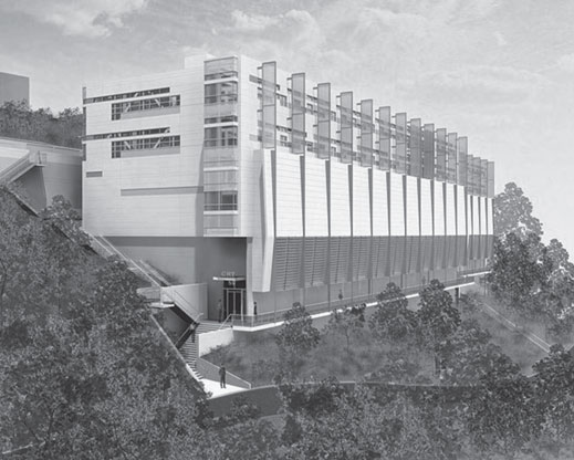
FIGURE 3.10: Artist’s rendering of the new Computational Research and Theory facility at Berkeley Lab.
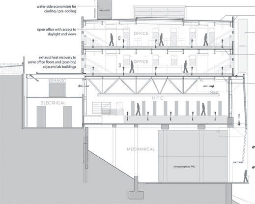
FIGURE 3.11: A cross-section of NERSC’s CRT data center, opening in 2015. The bottom mechanical floor houses air handlers, pumps and heat exchangers. The second floor is the data center; the top two floors are offices.
The San Francisco Bay Area climate is strongly moderated by the bay itself. Temperatures remain relatively cool year-round, and on those occasions when temperatures rise above the 70s, humidity stays low. The design of CRT leverages this benign environment to provide year-round cooling without mechanical chillers, which consume large amounts of power (Figure 3.11).
On the air side, the building is designed to “breathe,” taking in outside air to cool systems and expelling the hot exhaust generated by the systems. Hot air can be recirculated to temper and dehumidify the inlet air. (Heat is also harvested to warm office areas.) On the water side, evaporative cooling is used to dissipate heat from systems. Water circulates through cooling towers, where it is cooled by evaporation. This outside, open water loop is connected by a heat exchanger to a closed, inside water loop that provides cool water directly to the systems. The water loop additionally provides cooling for air on hot days.
Many data centers utilize free cooling when the conditions are amenable, and fall back on chillers when temperatures and humidity rise. For example, free cooling may be used in the winter but not in summer, or at night but not during the day. In the Bay Area conditions are favorable all year. In the worst conditions, which occur only a few hours per year, CRT is designed to provide 74°F air and 75°F water. For this reason, NERSC has decided to attempt to forgo chillers altogether. As a result, the maximum PUE at CRT is predicted to be less than 1.1 for a likely mix of equipment.
NERSC’s early experience with Edison was invaluable in understanding how to operate in a free-cooling environment, before we move into the CRT building. In addition, we have increased pump capacity in CRT and have added requirements for flow rate, differential pressure, and water quality to requests for proposals (RFPs) for future systems.
3.4.2 Cray XC30 Cooling Design
The Cray XC30 system has an innovative cooling mechanism that uses a side-to-side airflow where the exhaust air from one rack becomes the intake air of the next (Figure 3.12). Each cabinet contains a water intercooler (radiator) on the outlet side. This transfers heat from the air blowing through the cabinets to the water loop and cools air delivered to the next cabinet in the row. Fan cabinets are placed at the intake and outlet ends of the row as well as interspersed between pairs of two compute racks.
Flowing the air from side to side has unique advantages. First, additional cabinets in a row do not require more air from the computer room than was supplied to the first rack. Less overall air requirements means fewer building air handlers and greater overall center efficiency.
Additionally, the surface area of the side of the rack is greater than the front and the width of the rack is less than the depth. Both of these contribute to less fan energy required to move the same volume of air through a compute rack. With the air moving more slowly across an intercooler, a greater amount of heat is extracted per volume. This leads to a closer temperature approach between the water used to cool the system and the air that is being cooled, and a greater change in temperature of both the air (cooling) and the water (warming) through the system.

FIGURE 3.12: The Cray XC30 side-to-side airflow design.
Approach is the difference between the water temperature and the exiting air temperature. The slower the air moves through the coil (more time to transfer the heat) and the more efficient the coil is, the smaller the approach will be. Approach can get to a few degrees on a very efficient system but can never be zero. Depending on the direction of water flow through the intercooler, the approach can be the difference between the exiting water and the exiting air (parallel flow) or the entering water and the exiting air (counter flow). Since the entering water is always colder than the exiting water, it is more efficient to have the water flow in the opposite direction of the air. Counter-flow is required for efficient free cooling, and is included in the XC30 design.
Since the OSF and CRT sites are nearby and share the same climate, the free cooling approach was also implemented at OSF as a way to prototype the CRT design and understand system requirements. In addition, power cost savings were calculated at 80%, or 216 kW per year [6].
NERSC users have access to a wide array of consulting and support services designed to increase their scientific productivity through technical support, education, advocacy, and the development and deployment of new computational and data technologies. NERSC provides problem management and consulting, help with user code optimization and debugging, strategic project support, web documentation and training, and third-party applications and library support for its diverse set of users.
NERSC’s User Services group comprises 12 consultants, including nine HPC experts, six with Ph.D. degrees. NERSC’s two account support personnel each has 10+ years of experience. NERSC’s consultants and account support staff are available to users via email, a web interface, and on the phone during business hours (8 a.m.-5 p.m. Pacific Time). Account support is available via the NERSC operations staff 24 x 7, 365 days a year, with many capabilities also available online.
When users contact NERSC, they immediately are in contact with highly trained HPC specialists who can usually solve issues directly or immediately route the request to the appropriate systems engineers. NERSC’s policy is to respond to all inquiries within four business hours, and either solve the problem or communicate a work plan to the user within three business days for all reported incidents.
Each month, NERSC’s consulting and support staff field about 140 user questions related to Edison. Users most often ask for assistance on how to run parallel jobs more efficiently, how to use software libraries and applications, how to debug and optimize code, and how to read and write data files at high performance. NERSC also helps users with data analytics and visualization related to their computations run on Edison.
3.6 Early Application Results on Edison
Since Edison Phase I first came online in early 2013, a number of NERSC users have been running very large data projects on the system. Here are some of their initial results [18, 3].
Edison’s 64 gigabytes of memory per node and faster processors are critical to the data-rich research of David Trebotich, a Berkeley Lab scientist who is studying the effects of sequestering carbon dioxide (CO2) deep underground to better predict the physical and chemical changes it will cause and where all the CO2 will wind up. Trebotich is modeling the physical and chemical changes sequestered CO2 causes in the rocks and saline reservoirs it is pumped into deep underground. Such “geologic sequestration” is already in use at some sites, but scientists still cannot predict its behavior using flow simulations that zoom in no closer than meters.
To get the detail necessary for accurate predictions, Trebotich’s models calculate the physical and chemical reactions at a resolution of 1 micron, generating datasets of one terabyte for a single, 100 microsecond time-step – 16 seconds for the full simulation (Figure 3.13). Edison’s high memory-per-node means that more of each calculation (and the resulting data) can be stored close to the processors working on it. As a result, the simulations run 2.5 times faster than on the previous flagship system, reducing the time it takes him to get a solution from months to weeks.
3.6.2 Large-Scale Structure of the Universe
Zarija Lukic, a cosmologist with Berkeley Lab’s Computational Cosmology Center (C3), models mega-parsecs of space in an attempt to understand the large-scale structure of the universe. Working with 2 million early hours on Edison, Lukic and collaborators performed the largest Lyman alpha forest simulation to date: the equivalent of a cube measuring more than 300 million light years on each side (Figure 3.14). Such large-scale simulations will be key to interpreting the data from many upcoming observational missions, including the Dark Energy Spectroscopic Instrument (DESI). The work supports the Dark Universe project, part of the DOE’s Scientific Discovery through Advanced Computing (SciDAC) program.
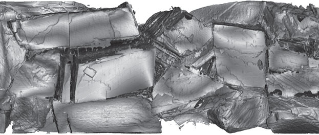
FIGURE 3.13: Simulation showing computed pH on calcite grains at 1 micron resolution. (Image: David Trebotich.)
3.6.3 Graphene and Carbon Nanotubes
Vasilii Artyukhov, a post-doctoral researcher in materials science and nanoengineering at Rice University, used 5 million processor hours during Edison’s testing phase to simulate how graphene and carbon nanotubes are “grown” using chemical vapor deposition. His goal is to develop a theory for the growth of carbon nanotubes to be able to selectively grow the ones that are most needed.
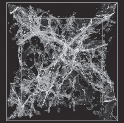
FIGURE 3.14: Using the Nyx code on Edison, scientists were able to run the largest simulation of its kind (370 million light years on each side) showing neutral hydrogen in the large-scale structure of the universe. (Image: Casey Stark.)
Edison’s Aries interconnect wired in the Dragonfly configuration allowed Artyukhov to run his code on twice as many processors, at speeds twice as fast as before. Artyukhov is also running codes that work at the molecular level that are not as computationally demanding, but because Edison is so large, he is able to run many of them at once.
3.6.4 Better Combustion for New Fuels
Jackie Chen of Sandia National Laboratory (SNL) is investigating how to improve combustion using new engine designs and new fuels – such as biodiesel, hydrogen-rich “syngas” from coal gasification, and alcohols like ethanol. She models the behavior of burning fuels by simulating the conditions found in these combustion engines, using a direct numerical simulation code developed at SNL (Figure 3.15).
During Edison’s early science period, she and post-doctoral researchers Hemanth Kolla and Sgouria Lyra modeled hydrogen and oxygen mixing and burning in a transverse jet configuration commonly employed by turbine combustors in aircraft engines and industrial power plants.

FIGURE 3.15: This volume rendering shows the reactive hydrogen/air jet in crossflow in a combustion simulation. (Image: Hongfeng Yu, University of Nebraska.)
Chen was able to run her direct numerical simulation code, S3D, on 100,000 processors at once and observed a 4x-5x performance improvement over the Cray XE6 (Hopper). They were also pleased with the I/O performance on file systems, with a write performance of about 6-10 GB/s and read performance of around 2.5 GB/s.
3.7 Exascale Computing and the Future of NERSC
A critical strategic objective at NERSC is to meet the ever growing computing and data needs of our users by providing usable exascale computing and storage systems, transitioning SC codes to execute effectively on many-core architectures, and influencing the computer industry to ensure that future systems meet the mission needs of SC.
The aggregate computing needs of SC science teams at NERSC will be well into the exascale regime by the end of the decade. Users need to run simulations at hundreds of petaflops, and they need to run thousands to millions of petascale simulations to achieve their goals. Following Edison (NERSC-7), NERSC will deploy pre-exascale systems in 2016 (NERSC-8) and 2019 (NERSC-9), and we anticipate deploying our first exascale system, NERSC-10, in 2022. Our goal is to provide our users a consistent path to exascale, particularly in the evolution of the programming model.
NERSC will continue to support MPI into the foreseeable future so that our codes can execute, albeit at less than optimal performance, on future systems with little or no modifications. We anticipate that many of our codes will transition to MPI for interprocessor communication plus OpenMP for on-node concurrency in the NERSC-8 time frame.
3.7.1 NERSC-8 as a Pre-Exascale System
The NERSC-8 system will be a Cray XC system delivered in 2016 that will provide over 10 times the sustained performance of NERSC’s Hopper system, a 1.2 peak petaflop Cray XE6 system. In addition to increasing the computational capability available to DOE computational scientists, the NERSC-8 system will also begin to transition DOE scientific applications to more energy-efficient, manycore architectures.
The system, named Cori in honor of bio-chemist and Nobel Laureate Gerty Cori, will be composed of over 9300 single-socket compute nodes using Intel’s next-generation Xeon Phi processor, code-named “Knights Landing.” The Knights Landing processor used in NERSC-8 will have over 60 cores, each with multiple hardware threads with improved single thread performance over the current generation Xeon Phi co-processor. The Knights Landing processor is “self-hosted,” meaning that it is not an accelerator or dependent on a host processor. With this model, users will be able to retain the MPI/OpenMP programming model they have been using on NERSC’s Hopper and Edison systems. The Knights Landing processor also features on-package high bandwidth memory that can be used as a cache or explicitly managed by the user.
Additionally, Cori will provide over 400 GB/s of I/O bandwidth and 28 PB of disk space. The Cray XC features the Aries high-bandwidth, low latency network for inter-node communication. The system will be installed directly into the new CRT facility in 2016.
Included in the NERSC-8 contract is an option for a Burst Buffer, a layer of solid-state flash storage meant to address the persistent and growing gap between memory performance and disk performance. The initial design for the Burst Buffer was focused on check-point restart, a means for applications to restart in case of interruption. However, NERSC’s use cases are much broader, including the need to quickly access large datasets generated at DOE experimental facilities.
By using solid-state flash storage, a Burst Buffer can provide many times the bandwidth of a similarly priced pure disk solution as well as significantly better random, small-block I/O characteristics. Thus, leveraging the capabilities of solid-state flash and traditional disk-based parallel file systems into a single HPC system can provide both higher bandwidth and larger capacity than either solid-state flash or disk could provide alone for a given price.
While promising, the Burst Buffer technology is immature and the software to support it undeveloped. For this reason, the NERSC-8 system was designed to achieve the mission goals without a Burst Buffer. The Burst Buffer software will be developed through a separate Non-Recurring Engineering contract. Depending on Burst Buffer software development progress, NERSC may execute the option for a Burst Buffer.
3.7.1.2 Collaboration with ACES
NERSC has been and is continuing to collaborate with ACES (Alliance for Computing at the Extreme Scale, an HPC partnership between Los Alamos National Laboratory and Sandia National Laboratories) to procure the next generation systems for each organization: NERSC-8 and the Trinity system. NERSC and ACES collaborated informally in the past and, in 2010, independently procured very similar systems: Hopper, a Cray XE6 for NERSC, and Cielo, a Cray XE6 for ACES. The Office of Science and the National Nuclear Security Administration have been working together for many years, and most recently the two programs began partnering on DesignForward and FastForward, with the goal of developing critical technologies needed for extreme-scale computing.
There were numerous reasons that motivated the decision to work together on the NERSC-8 and Trinity projects. Principally, the collaboration supports the strategy of each program’s headquarters (SC and NNSA), which seek to leverage each other’s investments, provide a unified message to vendors during this time of rapidly changing technology in the HPC market, and build a broader coalition to overcome the challenges of transitioning the user communities to more energy efficient architectures.
TABLE 3.5: NERSC systems roadmap.
System |
PF |
Memory (TB) |
Storage (PB) |
BW (GB/s) |
Franklin |
0.35 |
77.4 |
0.93 |
28 |
Hopper |
1.3 |
216.6 |
2.4 |
70 |
Edison |
2.6 |
358.9 |
7.4 |
168 |
Cori (planned) |
>27.9 |
893.2 |
28.5 |
432 |
NERSC-9 |
250–500 |
10 PB |
300 |
4,000 |
NERSC-10 |
1,000 |
30 PB |
700 |
12,000 |
The NERSC-8 and Trinity teams have been working together since the spring of 2012 and created joint technical requirements, developed a common set of application benchmarks, and jointly conducted vendor market surveys. The teams released a joint RFP for a single vendor to procure two independent systems in the 2015/2016 timeframe, one for NERSC-8 and one for Trinity. Staff from ACES and NERSC participated in the RFP response evaluation and selected the vendor’s proposal that provided the best value system. After vendor selection, each team negotiated its own contract, though the teams were in close contact during negotiations, each observing the negotiations of the other. The Trinity and NERSC-8 teams will continue to collaborate through the delivery, integration, testing, and acceptance of the systems. While the two teams are collaborating, each project has its own mission drivers and contract.
The NERSC systems roadmap is shown in Table 3.5. Note that Memory and Storage figures are calculated using Base 10.
Computing technology is undergoing major changes because chip hardware technologies are reaching physical scaling limits imposed by power constraints. Although transistor density continues to increase, chips are no longer yielding faster clock speeds; as a result, vendors are increasing the number of cores on a chip.
The HPC community at large is facing a challenge to prepare applications for these future architectures. From the most conservative architecture choice to the most exotic architecture choice a center like NERSC could adopt in the exascale time-frame, there are several common design elements. First, increased parallelism will be seen in increased core per node and threads per core, and increased vector lengths will also be prevalent. Second, memory per core/thread will decrease. Third, fast local memories will emerge and require explicit management by user programs.
These architecture innovations with vast increases in chip parallelism (referred to as “manycore”) and new memory hierarchies are incorporated into the NERSC-8 Knight’s Landing (KNL) processor, which will have more than 60 cores per node with multiple hardware threads each, and high bandwidth on-package memory. Although it will be straightforward to get applications running on the system, it is expected that many user applications will require code modifications to achieve high performance. The amount of code modification and restructuring will depend on many factors, including the extent to which users had begun transitioning to MPI+X programming models on existing, current-generation NERSC and DOE platforms. Achieving high performance on the KNL processor will likely require finer levels of parallelism, increased vector lengths, and utilization of on-package memory.
Well before the NERSC-8 architecture was selected, NERSC had assembled an Application Readiness team, comprising approximately 12 staff members, to examine how NERSC’s approximately 600 applications would fare, performance wise, in light of these trends and estimate how much work it would take to optimize an application on an architecture with more on-node parallelism. With the NERSC-8 architecture identified, the Application Readiness effort will ramp up as a broad, multi-pronged effort that includes user training, access to early development systems, application analysis deep dives, and collaborations with vendors and other members of the HPC community who are facing the same transition to manycore architectures. Preparing users and their applications for advanced architectures is a long-term NERSC initiative and, as such, will last longer than the duration of the NERSC-8 project, well into NERSC-9 and beyond. NERSC plans to develop and deliver a rigorous and comprehensive training program to ensure that NERSC’s end-user customers are adequately prepared for the new system.
NERSC has had substantial vendor support from Intel and Cray to aid in the transition of users to the KNL architecture. Before the NERSC-8 system arrives Intel will provide “white-box” test systems with early KNL processors. These single-node systems will provide NERSC staff and NERSC users an early opportunity to test and port codes to an early KNL architecture. Intel will also provide deep dive dungeon code sessions to help code teams transition to the KNL architecture.
NERSC will also form a partnership with Cray for a Center of Excellence (COE) comprising NERSC Application Readiness Staff and Cray staff. The COE was launched in the fall of 2014, and Cray staff will be tasked with helping to port and optimize key DOE SC applications to the KNL. As part of the Application Readiness effort, NERSC plans to create integrated code teams composed of NERSC principal investigators, Cray COE staff, NERSC Application Readiness staff, and newly hired postdoctoral researchers to aid in each application’s transition.
NERSC has examined the top applications running on NERSC systems and has completed a preliminary analysis of each code’s readiness for the NERSC-8 system. Several NERSC top application codes run on the Leadership Computing Facilities at Oak Ridge and Argonne, and many of them are already well prepared for the NERSC-8 system. Other application teams will need more guidance and help making the transition. NERSC will leverage best practices from the LCFs, ACES, and others in the HPC community to prepare its users for the NERSC-8 architecture. Additionally, because the Edison system will overlap with the NERSC-8 system, users who need to make substantial code changes will still be able to compute productively on the Edison (NERSC-7) system.
While transitioning the NERSC workload to manycore architectures presents several challenges, NERSC has developed a comprehensive plan and acquired the necessary resources to make it a success. Making this transition as smoothly and effectively as possible will allow our science teams to meet their goals in the 2015-2023 timeframe.
Edison is the first all-new Cray supercomputer design in nearly a decade. It features Intel processors and a new, higher performance interconnect (Aries) that uses a Dragonfly topology. The system can execute nearly 2.57 quadrillion floating-point operations per second (petaflop/s) at peak theoretical speeds. While theoretical speeds are impressive, however, NERSC’s longstanding approach is to evaluate proposed systems based on sustained performance on real applications to increase the scientific productivity of our users.
As a result, Edison was designed to optimize data motion – the primary bottleneck for many applications at NERSC – rather than peak speed. It has very high memory bandwidth, interconnect speed, and bisection bandwidth relative to its floating point operation speed. In addition, each node has twice the memory of many leading systems. This combination of fast data motion and large memory per node makes it well suited for NERSC’s traditional HPC workload and newly emerging data-intensive applications.
The authors wish to thank the Advanced Scientific Computing Research Program in the U.S. Department of Energy’s Office of Science, which supports NERSC under contract No. DE-AC02-05CH11231. The authors would also like to thank Cray Inc. for their numerous contributions to this document, notably the description and drawings of the Aries interconnect and Sonexion I/O system.
[1] Bob Alverson, Edwin Froese, Larry Kaplan, and Duncan Roweth. “the cray xc series network”. http://www.cray.com/Assets/PDF/products/xc/CrayXC30Networking.pdf. Cray Inc.
[2] K. Antypas, J. Shalf, and H. Wasserman. NERSC6 workload analysis and benchmark selection process. LBNL Technical Report - LBNL 1014E, August 13, 2008.
[3] Katie Antypas, Nicholas Wright, and Zhengji Zhao. Effects of hyper-threading on the NERSC workload on Edison. Cray Users Group (CUG), 2013.
[4] Nicholas P. Cardo. Sonexion 1600 I/O performance. Cray Users Group (CUG), 2013.
[5] Tina Declerck and Iwona Sakrejda. External torque/MOAB and fairshare on the Cray XC30. Cray Users Group (CUG), 2013.
[6] Brent Draney, Jeff Broughton, Tina Declerck, and John Hutchings. Saving energy with free cooling and the Cray XC30. Cray Users Group (CUG), 2013.
[7] Richard Gerber, Harvey Wasserman et al. Large scale computing and storage requirements for biological and environmental research. https://www.nersc.gov/assets/HPC-Requirements-for-Science/NERSC-BER-WorkshopReport.pdf, May 7-8, 2009.
[8] Richard Gerber, Harvey Wasserman et al. Large scale computing and storage requirements for high energy physics. https://www.nersc.gov/assets/HPC-Requirements-for-Science/NERSCHEP-WorkshopReport.pdf, November 12-13, 2009.
[9] Richard Gerber, Harvey Wasserman et al. Large scale computing and storage requirements for basic energy sciences. https://www.nersc.gov/assets/HPC-Requirements-for-Science/NERSCBES-WorkshopReport.pdf, February 9-10, 2010.
[10] Richard Gerber, Harvey Wasserman et al. Large scale computing and storage requirements for fusion energy sciences. https://www.nersc.gov/assets/HPC-Requirements-for-Science/NERSCFES-WorkshopReport.pdf, August 3-4, 2010.
[11] Richard Gerber, Harvey Wasserman et al. Large scale computing and storage requirements for advanced scientific computing research. https://www.nersc.gov/assets/HPC-Requirements-for-Science/NERSC-ASCR-WorkshopReport.pdf, January 5-6, 2011.
[12] Richard Gerber, Harvey Wasserman et al. Large scale computing and storage requirements for nuclear physics research. https://www.nersc.gov/assets/HPC-Requirements-for-Science/NERSCNP-WorkshopReport.pdf, May 26-27, 2011.
[13] Richard Gerber, Harvey Wasserman et al. Large scale computing and storage requirements for biological and environmental research - target 2017. https://www.nersc.gov/assets/HPC-Requirements-for-Science/BER2017/BER2017FinalJune7.pdf, September 11-12, 2012.
[14] Richard Gerber, Harvey Wasserman et al. Large scale computing and storage requirements for high energy physics - target 2017. https://www.nersc.gov/assets/pubs_presos/NERSC-PRR-HEP-2017.pdf, November 27-28, 2012.
[15] John Kim, Wiliam J. Dally, Steve Scott, and Dennis Abts. Technology-driven, highly-scalable dragonfly topology. SIGARCH Comput. Archit. News, 36(3): 77-88, June 2008.
[16] William Kramer. Percu: A holistic method for evaluating high performance computing systems. Technical Report No. UCB/EECS-2008-143, November 5, 2008.
[17] William Kramer, John Shalf, and Erich Strohmaier. The NERSC sustained system performance (SSP) metric. LBNL tech report, 2005.
[18] Zhengji Zhao. Comparing compiler and library performance in material science applications on Edison. Cray Users Group (CUG), 2013.