EPCC, University of Edinburgh
2.1.1 Sponsor/Program Background
2.2 Applications and Workloads
2.2.1 Highlights of Main Applications
2.4.1 Compute Node Architecture
2.4.3 Service Node Architecture
2.4.4 External Login Nodes (esLogin)
2.4.5 Pre- and Post-Processing Nodes
2.5.2 Job Submission System: PBS Pro/ALPS
2.7 Long-Term Storage and Data Analytics
2.7.1 UK Research Data Facility Overview
2.7.2 UK-RDF Technical Details
2.7.3 Access to the UK-RDF and Moving Data
2.8.3 Innovations and Challenges
2.10 SAFE: Service Administration from EPCC
2.1.1 Sponsor/Program Background
ARCHER is the latest UK national HPC service and is funded by two major UK research councils — the Engineering and Physical Sciences Research Council (EPSRC) and the Natural Environment Research Council (NERC). EPSRC users typically work on Chemistry, Materials, Physics, Computational Fluid Dynamics, and Engineering. NERC users work on Ocean Modelling, Atmospheric Science, and Mineral Physics. More details are given in Section 2.2.
EPSRC and NERC have contributed to a series of national HPC systems during the last 20 years.
Table 2.1 lists the series of overlapping national UK HPC services. Each service has lasted 7-8 years and has had a number of significant technology refreshes. There have also been overlaps between consecutive services to ensure smooth transitions for users.
EPCC took leading roles in all of the above services, apart from CSAR. However, EPCC’s history of systems is significantly more extensive. In particular, the University of Edinburgh’s first parallel systems were DAPs and Meiko transputer systems in the 1980s. These were followed by a Connection Machine and a Meiko i860 system at the beginning of the 1990s; these systems marked the birth of EPCC.
TABLE 2.1: National parallel HPC systems in the UK.
Service |
Vendor |
Years |
T3D/T3E |
Cray |
1994-2002 |
CSAR |
SGI |
1998-2006 |
HPCx |
IBM |
2002-2010 |
HECToR |
Cray |
2007-2014 |
ARCHER |
Cray |
2013-2017+ |

FIGURE 2.1: Peak performance of EPCC systems during the last 35 years.
The graph in Figure 2.1 shows the performance of the major systems at Edinburgh during the last 35 years. For comparison, the graph also includes a line reflecting Moore’s Law and a plot of the peak performance of the systems at number 20 on the Top 500 list [4].
The graph shows an exponential increase in performance at EPCC, even somewhat ahead of Moore’s Law. When we first plotted this graph about 10 years ago, we predicted that EPCC would have a Petaflop system in 2014; ARCHER met this prediction towards the end of 2013. The graph also shows that the leading systems within the UK are consistently within the top 20 largest systems in the world. The peak performance of ARCHER does not yet include any accelerators and so we are confident that it is one of the largest general-purpose HPC systems in the world and will deliver world-class research.
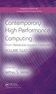
ARCHER will support more than 3000 users from throughout the UK working on a wide variety of applications areas. At this stage in the service, there are only limited statistics on usage, but the pattern is expected to be similar to the previous national service, HECToR. HECToR had more than 3000 users. Around half of the users were UK nationals, while the other half came from more than 80 different countries. These users came from more than 50 different UK universities and higher education institutes, including all of the major research institutions. The map in Figure 2.2 shows the distribution of users across the UK.
The map shows that UK national HPC systems attract users from throughout the UK, representing most of the major research universities. Although there are significant groups of users associated with major centers of computational research (London, Manchester, Oxford, Cambridge, Edinburgh,…), there are noticeable similarities with the maps of population density produced by the UK’s Office of National Statistics (http://www.ons.gov.uk/). The map indicates the broad importance of HPC across the UK.
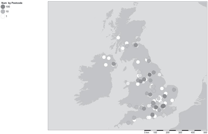
FIGURE 2.2: Map of user distribution across the UK.*
The procurement of ARCHER took exactly two years from the initial award of funding through to full user service. The key dates are shown in Table 2.2.
EPSRC, as managing agent for ARCHER, set up a technical procurement working group (PWG) consisting of representatives from both users and service providers. Their initial task was capturing the requirements of the users. The key elements of this process were a questionnaire circulated to users of the existing HECToR service and other interested parties, and a user meeting where the key issues were discussed; these occurred in March 2012. In parallel with this, there were also initial meetings with possible vendors. These meetings led to a slight delay in the procurement timeline so that the vendors would be able to offer the new Intel Ivy Bridge processors.
TABLE 2.2: Key dates for the ARCHER service.
Month |
Key Event |
December 2011 |
Funding secured |
March 2012 |
User meeting and questionnaire |
October 2012 |
Draft Statement of Requirements |
November 2012 |
Initial responses from vendors |
January 2013 |
Final bids from vendors |
February 2013 |
Vendor bids evaluated |
April 2013 |
Vendors informed of outcome |
August 2013 |
Hardware delivered |
September 2013 |
Installation |
October 2013 |
Final acceptance tests |
October 2013 |
Early access began |
December 2013 |
Full service |
The draft Statement of Requirements was published in October 2012 and vendors were encouraged to submit initial responses. After minor changes to this Statement of Requirements, the final bids were submitted and evaluated in early 2013. Cray were told that they were the preferred bidder in April 2013.
There were then separate procurements for the Service Provision (operations and service desk) and in-depth Computational Science and Engineering support. Both of these were ultimately awarded to UoE HPCX Ltd, a wholly owned subsidiary of the University of Edinburgh.
The ARCHER system was built in the USA and then shipped to Edinburgh in August 2013. The on-site acceptance tests were completed in October and some users were offered early access. The full user service started in December 2013.
2.2 Applications and Workloads
ARCHER supports a broad range of scientific application areas within the remit of the UK Research Councils, particularly the Engineering and Physical Sciences Research Council (EPSRC) and the Natural Environment Research Council (NERC), where computational codes are frequently used to address current scientific research challenges. In particular, the following eight scientific application areas are dominant: Materials Science and Chemistry, Nanoscience, Earth Sciences, Plasma Physics, Soft Matter Physics, Computational Fluid Dynamics, Physical Life Sciences and Big Data/Data Intensive Computing. The first six of these account for more than 80% of the time used on the UK’s National HPC resources (ARCHER and its predecessor HECToR); the other two areas (Physical Life Sciences and Big Data/Data Intensive Computing) are both areas that are becoming increasingly important to UK computational science.
1. Materials Science and Chemistry
Traditionally one of the largest areas of use on the UK’s national HPC facilities, ARCHER is being exploited by a broad range of applications in this area, underpinned by research communities such as the Materials Chemistry Consortium and the UK Car-Parrinello Consortium. Key codes include CP2K and VASP, which account for around 25% of the total time usage. In addition CASTEP, ONETEP and NWChem all exploit the ARCHER service.
2. Nanoscience
Significant use of ARCHER comes from Nanoscience applications. These are being used to exploit large-scale HPC facilities to model problems and phenomena that are simply not accessible using smaller-scale facilities. One of the largest of these is the GROMACS molecular dynamics package. This is primarily used for simulating biomolecules and is one of the most heavily used codes on our facilities. Other key applications in this area include GULP and LAMMPS.
3. Earth Sciences
This NERC-funded area of science has traditionally been a large consumer of HPC time in the UK and is a key community on the ARCHER service. This community is notable in that many of the users exercise not just parallel compute capability, but also require the ability to effectively pre- or post-process simulation data and to handle the transfer of extremely large data sets onto or off the service. The Fluidity ocean modelling application and ECMWFs IFS application are two important applications in this area. NEMO, the Unified Model (UM) MicroMag are also long-term users of our services.
4. Plasma Physics
The fusion community has been utilizing the UK HPC resources significantly over the past 5 years. The electromagenetic turbulence code Centori and the gyrokinetic simulation code GS2 codes are the main codes used in this area, with ELMFIRE and GENE also utilized on the system.
5. Soft Matter Physics
The current simulation method of choice for soft-matter simulations is the Lattice-Boltzmann (LB) approach that shows excellent potential for scalability on current and next-generation HPC systems. The Ludwig code is being used by researchers on ARCHER to study soft materials using a coarse-grained approach based on solution of the Navier-Stokes equations via the LB method. The LB3D code is being used for the study of complex fluids such as oil/water mixtures, surfactant systems and porous media flows. Finally, HemeLB is being used to simulate blood flow in realistic geometries (e.g., arteries).
6. Computational Fluid Dynamics
Computational Fluid Dynamics (CFD) simulations are being used on ARCHER in a range of scientific domains. Of particular importance is OpenFOAM, a widely used Open Source CFD framework. This is being used to study large turbine simulations within a hydroelectric power plant. The Gordon Bell winning Nek5000 code is also utilized on the system, as is the two-phase direct numerical simulation Navier-Stocks flow solver TPLS. Other codes include EBL, which is modelling a turbulence layer in the atmosphere, and FireGRID, a code being developed to model close-to-real-time modelling of fires.
7. Physical Life Sciences
The use of ARCHER to model systems in the life science domain and to perform computationally demanding analyses of biological/medical data is increasingly important. This community often has extremely large amounts of data and are sophisticated in their data management and handling. Codes include SPRINT, a general purpose parallel framework for the R statistical language, and The Advanced Complex Trait Analysis (ACTA) open-source software which is being used to understand the role played by genetics in a range of diseases.
8. Big Data/Data Intensive Computing
The amount of data produced by scientific instruments and simulations is expanding and supporting the management, analysis and transfer of huge data sets is a growing requirement of ARCHER. For example, the VERCE project - a pan-European FP7 project - is integrating the sharing and analysis of extremely large seismology data sets from disparate sources.
2.2.1 Highlights of Main Applications
ARCHER runs a wide variety of applications across multiple domains. The following are only a small selection of these.
1. CP2K performs atomistic and molecular simulations of solid state, liquid, molecular, and biological systems. Developments carried out on ARCHER’s predecessor have allowed specific scientific examples to achieve a 50% performance improvement. This work has involved improving the domain decomposition algorithms; introduced hybrid MPI/OpenMP parallelism; and improved the sparse linear algebra algorithms.
2. VASP is a plane wave electronic structure code which has been optimized for the use of the UK National systems. Work on VASP has been carried out to optimize the use of MPI collectives and the FFTW library in the application; and to introduce OpenMP parallelism to the exact-exchange part of the code. This has resulted in a 12x speedup for pure DFT calculations and the ability to exploit twice the number of cores effectively for exact-exchange calculations.
3. Fluidity is a multi-phase computational fluid dynamics code. Recent developments on ARCHER have included the addition of OpenMP to the matrix assembly routines; added threading to core functionality of the PETSc library, which is used as the linear solver engine; and optimized the mesh ordering using Hilbert space-filling curves.
4. GS2 — this gyrokinetic simulation code has been optimized to improve the FFT routines, to remove indirect addressing from core simulation routines, and to optimize the data decomposition using novel “unbalanced” decomposition ideas.
5. Ludwig is a lattice Boltzmann code being used to study soft materials. In particular it has been used to predict a new class of materials “bijels,” which are now patented and under investigation for commercial applications.
6. SPRINT — this general purpose parallel framework for the R statistical language is being used to allow the computation of time-dependent correlations between 14,000 gene expressions in control and pathogen-infected systems.
The ARCHER service is based around a Cray XC30 supercomputer that provides the central computational resource. This 3008 node MPP supercomputer is supported by a number of additional components including: high-performance parallel filesystems, pre- and post-processing facilities, external login nodes, and a large, resilient, long-term data facility (the UK Research Data Facility, UK-RDF).
TABLE 2.3: ARCHER 1 hardware configuration.
Feature |
Phase 1 (November 2013) |
Node Architecture |
Cray XC30 |
Processor |
Intel Xeon E5-2697, 12-core |
Processor microarchitecture |
Ivy Bridge (x86_64) |
Processor Frequency (GHz) |
2.7 |
Processor Count per Node |
2 |
Cores per Node |
24 |
Hardware threads per Node |
48 |
Node Memory Capacity (GB) |
64/128 |
Node PCIe |
Gen 3 |
Interconnection Network |
Cray Aries |
Interconnection Topology |
Dragonfly |
Latency |
1.3 ßs |
Bisection Bandwidth |
7200 GB/s |
Compute Racks |
26 |
Total number of nodes |
4920 |
Peak FLOP Rate (TF) |
2550.5 |
The Cray XC30 architecture itself consists of compute nodes connected together by the Aries interconnect and service nodes that act as interfaces for the file system, interfaces to external login nodes, and job launcher nodes.
The hardware that makes up the ARCHER service is summarized in Table 2.3 and described in more detail in Section 2.4.
The operating system is Cray Linux Environment, this consists of two components: fully featured Linux on the service nodes and an optimized version of Linux running on the compute nodes. This is described in more detail in the System Software section below.
Most standard compilers and tools are available along with the Cray Application Developer Environment to support the production of optimized parallel code. Table 2.4 provides details of the software installed on the system and the Section 2.5 describes the software in more detail.
In addition to the compute hardware, ARCHER comprises a number of different file systems and data analysis hardware. These include:
• NFS “home” filesystem — described in Section 2.4.
• Lustre “work” filesystem — described in Section 2.4.
• Post-processing nodes — high memory nodes for serial data processing. Described in Section 2.4.
• UK Research Data Facility — long-term data storage and data analytic hardware. Described in Section 2.7.
TABLE 2.4: ARCHER software configuration.
Feature |
Phase 1 |
Login Node OS |
Cray Linux Environment 5.1 |
Compute Node OS |
Cray Linux Environment 5.1 |
Parallel Filesystem |
Lustre/GPFS |
Compilers |
Intel 14/15 |
GCC 4.8/4.9 |
|
Cray Compiler Environment (CCE) 8.2/8.3 |
|
MPI |
Cray MPI |
SHMEM |
Cray SHMEM |
Coarray Fortran |
via CCE |
Unified Parallel C |
via CCE |
Notable Libraries |
Cray LibSci |
Intel MKL |
|
PETSc |
|
NetCDF |
|
HDF5 |
|
Hugetables |
|
GSL |
|
SLEPc |
|
Python |
2.7.6, 3.3.3 |
mpi4py |
|
Numpy |
|
Matplotlib |
|
Anaconda |
|
Job Scheduler |
ALPS |
Resource Manager |
PBS Pro |
Debugging Tools |
Allinea DDT |
GDB |
|
Cray ATP |
|
Performance Tools |
CrayPAT |
Allinea MAP |
|
Scalasca |
|
Vampir |
|
Cray Reveal |
2.4.1 Compute Node Architecture
ARCHER compute nodes each contains two 2.7 GHz, 12-core E5-2697 v2 (Ivy Bridge) series processors. Each of the cores in these processors can support 2 hardware threads (Hyperthreads). Within the node, the two processors are connected by two QuickPath Interconnect (QPI) links.
Standard compute nodes on ARCHER have 64 GB of memory shared between the two processors. There are a smaller number of high-memory nodes with 128 GB of memory shared between the two processors. The memory is arranged in a non-uniform access (NUMA) form: each 12-core processor is a single NUMA region with local memory of 32 GB (or 64 GB for high-memory nodes). Access to the local memory by cores within a NUMA region has a lower latency than accessing memory on the other NUMA region.
There are 4544 standard memory nodes (12 groups, 109,056 cores) and 376 high-memory nodes (1 group, 9,024 cores) on ARCHER giving a total of 4920 compute nodes (13 groups, 118,080 cores).
At zero load the compute nodes on ARCHER draw approximately 700 kW of power and at full load they draw approximately 2000 kW of power.
The Cray Aries interconnect links all compute nodes in a Dragonfly topology. In the Dragonfly topology 4 compute nodes are connected to each Aries router; 188 nodes are grouped into a cabinet; and two cabinets make up a group. The interconnect consists of 2D all-to-all electric connections between all nodes in a group with groups connected to each other by all-to-all optical connections. The number of optical connections between groups can be varied according to the requirements of the system. ARCHER has 84 optical links per group giving a peak bisection bandwidth of over 11,090 GB/5 over the whole system. The MPI latency on Aries is 1.3 μs with an additional 100 ns of latency when communicating over the optical links. This additional latency is generally not visible to end users as it vanishes into the noise associated with the communications software stack.
2.4.3 Service Node Architecture
The ARCHER service nodes each contain two 2.6 GHz, 8-core Xeon E5-2650 v2 (Ivy Bridge) series processors.
The service nodes provide a number of different functions on ARCHER: PBS job launcher (MOM) nodes, LNET routers (for connecting to the filesystems) and others. The service nodes are internal to the XC30 hardware and are collocated in the cabinets with the compute nodes.
2.4.4 External Login Nodes (esLogin)
The ARCHER login nodes are external to the main XC30 system and are therefore available for use even when the compute portion of the facility is out of service. They have access to all the filesystems on ARCHER and also have the full Cray application development environment installed. This means that data can be accessed, programs compiled, and pre- and post-processing performed when the compute nodes are unavailable.
The esLogin nodes each has two 2.6 GHz, 8-core Xeon E5-2650 v2 (Ivy Bridge) series processors. There are eight login nodes provided to ARCHER users.
2.4.5 Pre- and Post-Processing Nodes
The two ARCHER post-processing (PP) nodes each contains four 2.0 GHz, 10-core Intel Xeon E7-4850 (Westmere) series processor giving a total of 40 physical cores (80 hyperthreads) available on each node. Each PP node has 1 TB physical memory available.
The PP nodes are available to users by two methods:
• Through the PBS Pro job submission system.
• By direct interactive access via the ARCHER login nodes.
As for the esLogin nodes, the PP nodes are usually available to use even when the compute portion of the system is unavailable. They also have the full Cray application development environment installed and mount all the ARCHER filesystems and the UK Research Data Facility (see below).
ARCHER has a number of different storage systems with different purposes:
• “home” — NFS filesystems for small-scale storage of critical data such as source code. See below for more details.
• “work” — Lustre filesystems for high-performance IO operations. See below for more details.
• UK Research Data Facility — GPFS-based system for long-term storage of large amounts of data. Described in more detail in Section 2.7.
All of the group and user quotas on the ARCHER filesystems can be queried and managed by project managers and service staff through the SAFE web interface described at the end of this chapter.
The ARCHER filesystems collectively draw approximately 40 kW of power and the RDF draws approximately 120 kW of power.
A set of four 50TB NFS filesystems designed to hold small amounts of critical project data such as source code and small input files. Each project on ARCHER is assigned space on one of the “home” filesystems and the allocation is balanced to try and achieve an even load across the full set.
The “home” filesystems are not available on the ARCHER compute nodes so any data that is required during simulations has to be stored on the “work” filesystems. The machine is specifically designed in this way to:
• avoid users seeing poor performance by mistakenly using the NFS filesystem for intensive IO operations;
• minimize the chances of the NFS filesystem becoming full with large output files from simulations.
The “home” filesystems are backed up, first to a second set of hard disks, and then to tape with a set of backups stored off-site for disaster recovery purposes.
A collection of three high-performance, parallel Lustre filesystems with a total of around 4 PB of available storage. Each project is assigned space on a particular Lustre partition with the assignments chosen to balance the load across the available infrastructure.
The “work” filesystems are designed for use during simulations for high-performance IO operations. Users can choose how many of the available file servers they stripe the data over. For large files using parallel IO operations using the maximum number of stripes usually gives best performance.
The Lustre filesystems are not backed up in any way and are not a scratch filesystem (as they are not periodically cleaned up). It is up to individual projects and users to manage their own data.
The operating system (OS) on ARCHER is the Cray Linux Environment (CLE) that in turn is based on SuSE Linux. CLE consists of two components: CLE and Compute Node Linux (CNL). The service nodes of ARCHER (for example, the esLogin nodes) run a full-featured version of Linux. The compute nodes of ARCHER run CNL. CNL is a stripped-down version of Linux that has been extensively modified to reduce both the memory footprint of the OS and also the amount of variation in compute node performance due to OS overhead.
2.5.2 Job Submission System: PBS Pro/ALPS
PBS Pro is used to schedule jobs. Users interact with PBS via job submission scripts and by using PBS commands on the esLogin nodes. All ARCHER job submission scripts run on Job Launcher Nodes rather than on the compute nodes themselves. These Job Launcher Nodes (sometimes also called MOM Nodes) are ARCHER Service Nodes that have permission to issue aprun commands to start jobs on the compute nodes. The Job Launcher Nodes are shared between users meaning that memory or CPU intensive serial commands are best placed in serial job submission scripts and run on the pre- and post-processing nodes.
Cray ALPS (Application Level Placement Scheduler) is used to launch and place parallel processes and threads. This provides fine grained control over which nodes and cores processes and threads run on. ALPS is initiated using the aprun command within a job submission script and is the only way to run jobs on the ARCHER compute nodes. Any commands launched within a script which are not launched with aprun will run on the Job Launcher Nodes. Options can be given to aprun to determine the total number of distributed processes, the number of distributed processes per compute node, the number of threads per distributed processes (i.e., the “stride” between processes) and the number of Intel Hyperthreads to use for each physical core (either 1 or 2).
ARCHER has queueing structure which allows for jobs of different lengths and sizes. Jobs can run for up to 24 hours any number of nodes (i.e., up to 118,080 processing cores with fully populated nodes) and up to 48 hours for jobs up to 128 nodes 3072 processing cores with fully populated nodes). Jobs are charged on completion according to the number of node-hours used. In addition, low priority jobs can run that are not charged but receive lower priority than charged jobs. The low priority access queue is only opened when the backlog in the queueing system drops below a certain threshold.
A typical job submission script contains just one aprun call to allow a parallel job to run. However, it is possible to run array style jobs on ARCHER using PBS allowing for multiple jobs to be run at once using the same submission script.
For jobs which do not fit into the above queue structure, users can apply to reserve a set of nodes for a fixed time period. This is particularly useful for occasional jobs running for more than 48 hours or for courses or demonstrations.
Pre- or post-processing jobs run on dedicated post-processing (PP) nodes. This is useful for long compilation, post-calculation analysis and data manipulation on single cores.
Interactive access to compute jobs and post-processing nodes is available via PBS allowing for the running and debugging of codes via the command line.
Tools such as bolt and checkScript have been developed to assist users in running scripts and checking their validity.
The bolt job submission script creation tool has been written by EPCC to simplify the process of writing job submission scripts for modern multicore architectures. Based on the options supplied by the user, bolt will try to generate a job submission script that uses ARCHER as efficiently as possible. This tool can generate job submission scripts for both parallel and serial jobs on ARCHER. MPI, OpenMP and hybrid MPI/OpenMP jobs are supported. If there are problems or errors in your job parameter specifications, then bolt will print warnings or errors. However, bolt cannot detect all problems so users can run the checkScript tool on any job submission scripts prior to running them to check for budget errors, etc.
In this section we outline the parallel programming models that can be used on ARCHER, the various languages that support these models and the compilers that implement them. We also cover the major libraries and tools that we support to assist users in application development.
Like almost all petascale systems that do not employ accelerators, usage of ARCHER is dominated by message-passing applications written using MPI. A pan-European survey by the PRACE project [2] showed that 88% of applications on the largest systems could run using basic message-passing operations, although just over half of these could also exploit threaded parallelism using OpenMP (see Section 2.6.1.4). The vendor-supplied MPI library provides an implementation of the MPI-3.0 standard via the Cray Message Passing Toolkit (MPT). Although in principle this supports additional models such as single-sided puts and gets, and a unified memory model allowing exploitation of shared memory without the use of threads, almost all codes still use traditional two-sided message passing. The ARCHER network hardware and MPI software are optimized by Cray for HPC applications to such an extent that users can achieve low latency and high bandwidth simply by using traditional MPI send, receive and collective operations.
Partitioned Global Address Space (PGAS) models, such as Unified Parallel C (UPC), Fortran Coarrays (CAF) and OpenSHMEM, have been the subject of much attention in recent years, in particular due to the exascale challenge. There is a widespread belief that existing message-passing approaches such as MPI will not scale to this level due to issues such as memory consumption and synchronization overheads. PGAS approaches offer a potential solution as they provide direct access to remote memory. This reduces the need for temporary memory buffers, and may allow for reduced synchronization and hence improved message latencies. Some modern distributed memory architectures allow for Remote Memory Access (RMA) directly over the interconnect, meaning the PGAS model maps directly onto the underlying hardware.
UPC extends the C language to allow for the declaration of logically shared data, even on a distributed memory system. UPC includes new data and work-sharing statements to give the user full control of how programs execute in parallel. Although typically classified as a PGAS language alongside CAF and OpenSHMEM, UPC takes quite a different approach to parallel data. In CAF and OpenSHMEM there are no data distribution directives: just as in MPI, accessing remote data requires the user to explicitly specify the remote processor. In UPC the user can reference a particular element of shared data and the compiler or runtime system works out if it is a local or remote access, and if remote which processor owns the data.
PGAS features have been introduced into the Fortran 2008 standard with coarrays. Programming using coarrays has many potential advantages compared to MPI. Amongst these are simplicity, compiler checking and scope for automatic optimization of communications by the compiler. Coarrays can also be introduced incrementally to existing MPI codes to improve performance-critical kernels.
Coarrays have a long history on Cray systems, with implementations dating back to 1998 on the Cray T3E. The original coarray extensions proposed by Bob Numrich and John Reid [9] were implemented as an option in Cray Fortran 90 release 3.1. The direct RMA capabilities of the T3E torus interconnect enabled this PGAS model to be implemented easily and efficiently.
The origins of OpenSHMEM, like Fortran coarrays, date back to the first Cray MPPs of the early 1990s. OpenSHMEM is a standardization of the various single-sided SHMEM models that evolved from the original Cray SHMEM. Unlike UPC and CAF, OpenSHEM is an API not a language extension. It includes single-sided puts and gets, various synchronization methods and collective operations.
The first generation of more modern Cray systems, the XT architecture, used the Seastar interconnect which had an underlying message-passing (i.e., two-sided) data-transfer model. As a result, PGAS approaches had to be implemented on top of some software layer such as GASNET [1] to emulate true RMA capabilities. However, ARCHER uses the ARIES interconnect which once again offers native RMA capabilities. UPC and CAF are supported natively by the Cray compilers, and OpenSHMEM is supplied as part of the Cray MPT. Studies of coarray performance on HECToR [7], a Cray XE6 system that was ARCHER’s predecessor, showed that the GEMINI network performed very well. As ARCHER has the next-generation ARIES network, PGAS performance is generally expected to be very good; initial studies of coarrays on ARCHER [8] support this.
Each node of ARCHER is a 24-way shared-memory machine. Running pure MPI applications with one process per core does not take full advantage of this feature. Although intra-node messages will be very fast as the system software can exploit the shared memory, users cannot explicitly exploit it using MPI alone (other than using the very new and largely untested memory model supported by MPI 3.0). As is standard in HPC, OpenMP is the method used by most users since it provides higher-level abstractions than POSIX threads, and is tailored to parallel programming. However, a pure OpenMP code can only use 24 cores (less than 0.3% of ARCHER) so shared-memory approaches are only useful in combination with distributed-memory (e.g., message-passing) models.
An exception to this is for pre- and post-processing where we expect OpenMP to be used on ARCHER’s large shared-memory “serial” nodes.
The standard way to run a parallel code on ARCHER is to run a single MPI process per core, i.e., 24 MPI processes per shared-memory node. However, there are a number of reasons in general why using a hybrid MPI/OpenMP model can be advantageous on modern systems:
• Replicated data;
• Poorly scaling MPI codes;
• Limitations of the MPI library for large process numbers;
• MPI implementation not tuned for SMP clusters.
The latter two reasons do not apply to ARCHER as Cray MPI easily scales to the full system size, and is well tuned for the SMP nature of the nodes. However, the first two reasons are features of the user application and may be relevant.
Running 24 separate processes can be wasteful in terms of memory as any replicated data (e.g., static lookup tables) needs to be stored 24 times on each node. With hybrid MPI/OpenMP, all the OpenMP threads can access a single copy of the data stored by the parent MPI process. In the limit of a single MPI process and 24 OpenMP threads, this means a single copy per node as opposed to 24 for pure MPI.
Although few HPC applications have large lookup tables, many have shared data in the form of halos round data arrays which store boundary values from neighboring processes. These halos can become a significant fraction of the total memory requirements, especially when local data volumes shrink with high core counts.
There are also situations where hybrid MPI/OpenMP can extend the scalability of existing MPI algorithms. For example, the simplest way to parallelize a 3D FFT on an N ×N ×N array is to use a 1D “slab” domain decomposition across one of the array dimensions, giving entire N × N slices to each MPI process. However, this limits the scalability of the algorithm to N processes, which is likely to be in the hundreds rather than the thousands. Rather than changing the algorithm to a more complicated 2D “pencil” decomposition, another approach is to parallelize within each existing slab using OpenMP. This extends the scalability of the algorithm to one MPI process per core, or 24 × N processes in total on ARCHER, which is a substantial improvement. Similar approaches have been used in the popular CP2K code [6], and these are expected to be useful on ARCHER.
Care always has to be taken with the way that MPI processes and OpenMP threads are placed on a node, but this is fairly simple to do using various options to Cray’s aprun job launcher. Users have very fine-grained control over which cores the processes and threads are scheduled. However, the NUMA node architecture on ARCHER means that data locality may also need to be considered. As ARCHER only has two NUMA regions per node (corresponding to the two sockets), this is not a serious issue if more than one MPI processes are used per node. The processes can be allocated evenly between the sockets using aprun, so threads will always access data from the socket on which they are executing and no code changes are required. However, with a single MPI process per node threads can access data from both sockets so it is important to do NUMA-aware data allocation. Although this is quite easily done, as memory is allocated on a first-touch basis, it may require code changes. The easiest approach is to perform data initialization in parallel (even if this operation is not in itself time-critical) which can have significant performance benefits. Initial results on ARCHER show this clearly: NUMA-aware memory allocation doubles the performance of memory-bound OpenMP threaded codes running on 24 cores.
Although their inter-operation is not completely standardized, a few users have experimented with exotic hybrid models. For example, using MPI, OpenMP and Fortran coarrays all at the same time has given performance benefits in the IFS code [5].
The fundamental HPC programming languages of Fortran, C and C++ are all supported by multiple compilers. On ARCHER, users can choose between the compilers listed in Table 2.5.
The default environment is the Cray one, although users can easily select an alternative by loading different modules. Compilers should always be referred to by their generic names (ftn, cc, CC), with the specific compiler being selected automatically depending on the currently loaded module. As mentioned previously, UPC and Fortran Coarrays are fully supported on ARCHER by the Cray compilers.
TABLE 2.5: Supported compilers on ARCHER.
Module |
Product |
Specific Compilers |
PrgEnv-cray |
Cray Compilation Environment |
crayftn, craycc, crayCC |
PrgEnv-intel |
Intel Composer Suite |
ifort, icc, icpc |
PrgEnv-gnu |
GNU Compiler Collection |
gfortran, gcc, g++ |
Python is becoming increasingly widely used in the scientific community, and is supported on ARCHER. At scale, importing python modules can be very slow so we are installing the Anaconda distribution to solve this problem.
A number of performance tools are supported on ARCHER, including CrayPAT, Allinea MAP and Scalasca.
The Cray Performance Analysis Tool (CrayPAT) is a Cray-specific tool that is designed to give performance data on very large and complicated parallel codes. Using CrayPAT has three distinct stages:
1. use the pat_build command to create an instrumented executable from an existing standard executable;
2. run the instrumented executable which produces various files which store the performance results;
3. use pat_report to produce summary text information, or more detailed reports which can be viewed with Cray’s visualization tool Apprentice2.
At the pat_build stage, the user has very fine-grained control over what information is gathered from what portions of the code. However, to enable users easily to get a first impression of the overall performance of their code, this can be semi-automated as follows:
1. run an initial version instrumented using sampling;
2. feed the results of this sampling experiment back into pat_build by giving it the appropriate Automatic Profiling Analysis file (suffix .apa);
3. re-run the new executable which will be instrumented using a more detailed tracing approach, informed by the initial high-level sampling.
As it is provided by Cray, the CrayPAT tool is very closely integrated with the Cray compiler and runtime environment. For example, it is straightforward to find out the maximum amount of memory used by each process, or to find out how much time in an MPI collective call was spent in synchronization (which can be an indication of load imbalance).
Allinea MAP can be used to profile MPI code only - unlike CrayPAT, it does not support detailed profiling of OpenMP, SHMEM, CAF, or UPC. However, unlike CrayPAT it is a portable tool that is available on a wide variety of platforms. MAP is a commercial product, and on ARCHER we currently have license valid on up to 8192 cores.
Profiling using Allinea MAP consists of four steps:
1. set up a MAP profiling version of your MPI library (generally simple);
2. re-compile your code linking the MAP MPI profiling library;
3. run your code to collecting profiling information;
4. visualize the profiling using the MAP Remote Client.
MAP has been designed to have a small overhead, so results should generally be a good reflection of how the uninstrumented code actually behaves.
Figure 2.3 shows a typical run viewed with the Allinea Remote Client.
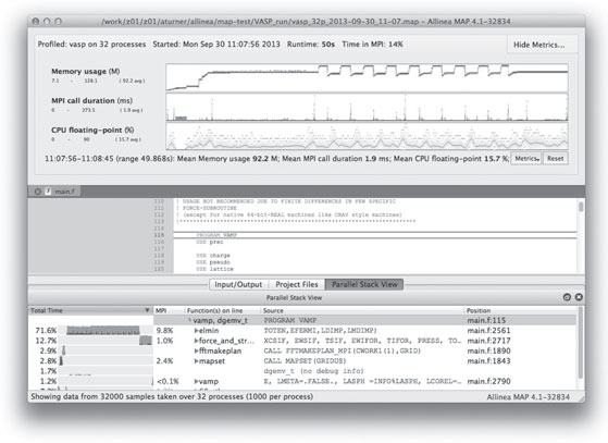
FIGURE 2.3: Typical MPI profiling output from Allinea MAP.
Scalasca [3] is “a software tool that supports the performance optimization of parallel programs by measuring and analyzing their runtime behavior. The analysis identifies potential performance bottlenecks - in particular those concerning communication and synchronization - and offers guidance in exploring their causes. It has been specifically designed for use on large-scale systems including IBM Blue Gene and Cray XC, but is also well-suited for small- and medium-scale HPC systems.”
Scalasca is distributed free of charge and is available on ARCHER, and its design means that it scales well and can be used to do performance analyses of large production codes.
The main debugging tool on ARCHER is Allinea DDT. DDT is a graphical debugging tool for scalar, multi-threaded and large-scale parallel applications. Running GUI-based applications on ARCHER and exporting the display is not recommended as network performance can severely limit the response time. The recommended way to use DDT on ARCHER is therefore to install the free DDT remote client on your workstation or laptop and use this to run DDT on ARCHER. As well as minimizing data transfer between ARCHER and the local machine, the client also enables job launching etc. to be controlled locally.
A typical view of the DDT debugging interface is shown in Figure 2.4.

FIGURE 2.4: Typical debugging session using Allinea DDT.
2.7 Long-Term Storage and Data Analytics
As described in the Hardware Section, there are three filesystems available to ARCHER users: the “home” filesystems, the “work” filesystems, and the UK Research Data Facility (UK-RDF).
The “home” and “work” filesystems have been described in detail in the Hardware Section above so here we concentrate on the UK-RDF.
The UK Research Data Facility (UK-RDF) is external to the UK national HPC services, and is designed for long-term data storage. The RDF consists of 13.86 PB disk, with an additional 30 PB of offsite backup tape capacity. Data is backed up daily and the backup capability is managed via Tivoli Storage Manager.
2.7.1 UK Research Data Facility Overview
The UK-RDF, funded by EPSRC and NERC, is collocated with ARCHER and is housed at the ACF facility.
The Research Councils’ vision behind the RDF includes:
• Provides a high capacity robust file store;
• Persistent infrastructure — will last beyond any one national service;
• Easily extensible in size and number of hosts — degree of future proofing and potential for increasing local post-processing activities;
• Operates independently of any one vendor’s offering for compute;
• Remotely accessible via an Edinburgh host — not restricted to through login nodes;
• Removes end of service data issues — transfers at end of services have become increasingly lengthy;
• Ensures that data from the current ARCHER service is secured — this will ensure a degree of soft landing if there is ever a gap in National Services.
The RDF currently hosts a range of filesystems (see Table 2.6). We expect the range and type of fielsystems and data infrastructure to expand significantly as the facilty matures.
2.7.2 UK-RDF Technical Details
The disk storage is based on four DDN 10K storage arrays populated with near-line SAS 3 TB 72000 rpm HDDs. Metadata storage is based on two IBM DS3524s populated with SAS 300 GB 10 krpm HDDs.
TABLE 2.6: Current filesystems on the UK-RDF.
Filesystems on RDF |
Disk capability |
Primary use |
/dirac |
107 TB |
Data storage from DiRAC Bluegene/Q system |
/nerc |
2.7 PB |
Data storage, NERC projects on ARCHER |
/epsrc |
770 TB |
Data storage, EPSRC projects on ARCHER |
/general |
171 TB |
Data storage, other projects on ARCHER |
/INDY |
43 TB |
Industrial data from INDY cluster |
/roslin (RDF pilot) |
193 TB |
Data analytics for sequence data from Roslin Institute |
/euclid (RDF pilot) |
513 TB |
Data analytics for University of Edinburgh gene sequencing service |
In addition to the 13.86 PB disk, the RDF has 30 PB of offsite backup tape capacity. Data on the RDF is backed up daily using Tivoli Storage Manager, based on an IBM TS3500 tape library with 12 drives.
Table 2.7 summarizes the connectivity to the RDF both externally through JANET (the UK academic network backbone) and to different facilities.
The future plan for the network also includes plans to connect the RDF core switches directly to JANET at 40 Gb/s. The first stage of this 40 Gb/s to ACF routers will happen fairly soon.
The RDF also includes a Data Analytic (DA) cluster with 24 nodes:
• 20 nodes have 2 10-core Intel E5-2660v2 (Ivy Bridge) 2.2 GHz processors, 128 GB RAM, 2 TB local disk
• 4 nodes have 4 8-core Intel E7-4830 (Ivy Bridge) 2.13 GHz processors and 2 TB RAM, 8 TB local disk
These nodes all have dedicated Infiniband links to the RDF storage with bandwidths of 2*56 Gb/s to each node to allow for large-scale data analysis.
2.7.3 Access to the UK-RDF and Moving Data
The RDF is directly mounted on ARCHER. Data transfer across from the “home” and “work” filesystems can be achieved by the standard commands such as cp. The native cp command was found to be able to give the best performance on transferring data from ARCHER filesystems to the RDF.
TABLE 2.7: Summary of UK-RDF Connectivity.
Connected to |
Bandwidth |
Notes |
JANET (UK Academic Internet Backbone) |
1 Gb/s |
The DTNs and the compute nodes which ultimately become headnodes/vms are currently connected at 1 Gb/s. |
PRACE |
N/A |
10 Gb/s connection to pan-European PRACE network planned for the near future. |
JASMIN |
1 Gb/s |
Dedicated 1 Gb/s light path through JANET to JASMIN climate and earth system science data facility. Planned upgrade to 2 Gb/s in near future. |
ARCHER |
2*10 Gb/s |
|
Data Analytic Cluster |
2*56 Gb/s |
DAC nodes are connected directly to disk storage at 2*56 Gb/s. |
Data Transfer Nodes |
2*10 Gb/s |
DTNs are connected to GPFS servers at 2*10 Gbs. |
DiRAC BG/Q |
N/A |
No connection at the moment but is intended to have a bandwith of 10 Gb/s in the future. |
The RDF is also mounted on EPCC’s industry-focused compute cluster: INDY and provides a long-term data store for data produced on this machine.
Access to data on the RDF is not restricted to HPC facilities. The four Data Transfer Nodes (DTN) have been configured on the RDF to enable access at times when facilities are unavailable such as during maintenance sessions, and provide direct 10 Gb/s Ethernet connections to the outside world. In addition to the normal Linux data transfer commands such as scp, the DTNs have been configured to use Grid-FTP, part of the Globus Toolkit, that provides a mechanism to efficiently move large volumes of data. Grid-FTP has been found to be able to give the best performance in transferring data from external sites to the RDF.
The DA cluster has been set up to provide an extremely flexible resource for different scientific workflows. A number of modes of access are provided according to the needs and expertise of particular communities. These include:
• A standard linux build provided by ourselves including standard tools and a batch job submission system. Provided for communities with generic DA requirements and little/no expertise in building their own environments.
• Custom virtual data appliance managed by ourselves. Aimed at communities who have a custom DA requirement but who do not have all the expertise to manage their own virtual data appliance.
• Hosting of virtual data appliances managed by the community itself. We recognize that some user communities have the expertise and requirement to manage their own setup and we can host these instances on the DA cluster hardware.
For all of the above options we provide the ability to access data on the UKRDF via direct connections to the disk at 2*56 Gb/s over dedicated Infiniband links. The DA hardware is configured to ensure the strict separation and security of data between different communities unless there is a requirement to share the data.
These data appliances can also be used to publically expose the data via, for example, a web interface if this is required by the community.
ARCHER is located at the Advanced Computer Facility (ACF) at the Bush Estate on the outskirts of Edinburgh. The center opened in 1976 as the Edinburgh Regional Computing Centre. The site has evolved through three development phases (2004, 2007 and 2012) and at each phase power and cooling systems were designed and installed to match the expected loads. Operating efficiencies were high on the design agenda, and this has been reflected in the increasing overall efficencies of the plant and infrastructure as the facility has evolved. During the most recent development in 2012 the center was enlarged as part of a £12 M extension to accommodate the ARCHER service bringing the total capacity to around 7 MW.
The ACF now consists of three machines rooms, two having a floorspace of 280m2 and one larger room with a 500 m2 floorspace which houses ARCHER. For ARCHER a new 760 m2 plant room (see Figures 2.5 and 2.6) was constructed to supply cooling and power for ARCHER’s machine room. This plant room supplies the ARCHER machine room with up to 4 MW of power. When idle, ARCHER draws 600 kW rising to 2 MW when the system is fully loaded. The RDF is also located in the larger machine room drawing around 100 kW of power.
FIGURE 2.5: The pipework for the ARCHER cooling system.

FIGURE 2.6: The high-voltage switchroom supplying ARCHER with power.
Each phase of the ACF plant has been designed to allow for an increasing amount of “free cooling” whereby final heat rejection to the atmosphere can be achieved with the minimum of mechanical overhead.
The Power Usage Effectiveness (PUE) is defined as the ratio of the total energy consumed by the facility (including cooling, etc.) to that consumed by the system itself. The PUE target for the ARCHER infrastructure is a mean value of 1.10, with expected seasonal variations between 1.05 and 1.15.
In addition to the power supplied to the plant from the UK National Grid, a 2 MW standby diesel generator is provided for essential services. The generator has an 8-hour running capacity and provides potential STOR (Short Term Operating Reserve) capability for the UK National Grid.
2.8.3 Innovations and Challenges
The increase in efficiency has been due to careful operational monitoring allowing optimization to be applied, with increasing efficiency being designed in at each upgrade phase. As computer systems have become power-hungry, the equipment suppliers have moved towards liquid-cooling with an increase in cooling water temperatures enabling the optimized plant to maximize efficiency and mimimize the cooling overhead. These trends seem set to continue.
However, since the overwhelming bulk of the energy required to operate large HPC systems is consumed by the computing equipment itself, the onus is on the computer manufacturers (and indeed chip designers) to design in operating efficiences (cores switching off, internal power management of fans, more efficient power supplies, enhanced cooling water temperature requirements and so forth).
Getting the plant right helps, but the problem is better tackled at the source.
The ARCHER system commenced production operation on the 16th December 2013. It currently has 3063 active users from 88 different nationalities and 1123 projects.
Figure 2.7 shows utilization of the service against time. ARCHER utilizes a metric called an allocation unit (AU), where 0.015 kAUs represent an hour on a single ARCHER core. Prior to production operation commencing, the service ran an early access program for users. As a result utilization was significant from the first few days of the production service, steadily increasing to a peak in January 2014. Usage has remained similar since then, averaging 75% utilization in 2014 1st January 2014–30th November 2014 (see Figure 2.8).

FIGURE 2.7: ARCHER’s Aries interconnect.

FIGURE 2.8: ARCHER usage against time for the 16th December 2013 to the 16th December 2014 in allocation units. The large increase in the end is due to the size increase with Phase 2 installation.
Breaking this down into subject area, Figure 2.9 shows that chemistry and environmental codes utilize the majority of the time (using 36% and 37% of the machine, respectively). Engineering codes also play a major role, utilizing 16% of the resources.
Within these areas, further analysis over the month of April 2014 shows that the dominant codes are VASP, CASTEP, CP2K, GROMACS and WRF are the most dominant codes. This is shown in Figure 2.10.

FIGURE 2.9: ARCHER usage by subject area for the period 16th December 2013 to the 16th December 2014.

FIGURE 2.10: ARCHER usage by code for the period January–November 2014.
The range of job sizes utilized on the system are shown in Figure 2.11. It is clear that the majority of the jobs utilize between 1024 and 8192 cores, with a smaller percentage (12%) utilizing the highest core counts (larger than 8192). There is also a significant number of jobs in the range 129-1024 cores. These job sizes are, on average, slightly larger than job sizes on the previous UK National Service, HECToR, reflecting a long-term trend of increasing job size on these systems.
2.10 SAFE: Service Administration from EPCC
User management on the ARCHER service is handled by the SAFE (Service Administration from EPCC). This is a software system developed over the last decade by EPCC to manage High Performance Computing services such as ARCHER. It is a web-based system built using java-servlets and a SQL relational database. It is responsible for almost all aspects of user management ranging from user registration and service desk to resource management and reporting. One of the particular challenges of this type of service is that it is often entirely stand-alone, rather than being embedded within the wider IT service provision of an existing organization. This means that there is no pre-existing database of users or support infrastructure that can be utilized; all these functions need to be provided from scratch. On the other hand this allows us to implement these functions in a single tool providing a focused and well-integrated solution.
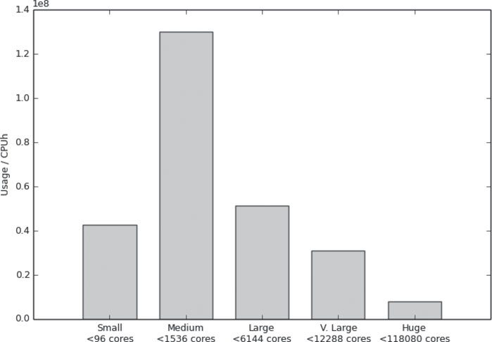
FIGURE 2.11: ARCHER usage by job size for the period January–November 2014.
One of the big advantages of this single integrated system is that it can easily be extended to allow many operations to be delegated to appropriate users. For example a project manager can approve access to, generate reports on, and manage resources within their projects. A similar level of integration would also have been possible with more traditional enterprise architectures where each function is implemented as a separate tool; however, a single code base allows for a more agile development process.
This ability to delegate operations to project managers is absolutely essential for ARCHER. Resource allocations are typically made to large projects. As these projects are large and complex there is often a need to support resource allocation to sub-groups within the project. These allocation decisions can only be made by the internal management within the project. In addition, the project membership is often quite fluid and decisions on membership of the sub-groups, and even membership of the project itself can also only be made by the project managers. It is therefore much more efficient to provide the project with the necessary management tools via a self-service web interface than to try and route all of these operations through a traditional help-desk as service requests. It provides a much better user interface for the project managers as requests can be validated for correctness in real time (for example ensuring that a disk quota request is not below the current usage within that quota). In addition, any requests that result in configuration changes to the service machine are mapped to a small set of well-defined change-tickets such as change-quota, new-user, password-reset, etc. For the ARCHER service, the implementation of these change-tickets has been largely scripted, though we choose to keep a manual approval step as part of the process rather than giving the SAFE the ability to make changes automatically.
The generation of reports and the analysis of system use is an important activity for any HPC service. There are many different groups that may require different levels of access to this data. Individual users need to be able to access information on their own use of the system. Project managers need to generate overview reports on the use by their project. System operators and funding agencies need reports on the overall use of the system. In addition reports need to be generated from a variety of different data sources. The reporting sub-system of the SAFE is capable of ingesting data from a variety of sources including most major batch systems. It uses a system of plug-in parsers to allow addition types of data source to be easily added to the system. The reporting system is not restricted to batch job information and can also handle such diverse information as project resource allocations, file-transfer activity or disk usage data. In addition, policy plug-ins can be used to trigger side effects such as job charging and to augment the raw information based on local site policies. For example, additional accounting properties can be derived based on the queue where the job runs, or additional log files can be parsed to add additional information such as executables used.
We chose to build a general purpose reporting system rather than focus solely on the generation of reports of jobs run on the HPC resource. This allows the same framework to be used to generate reports on disk utilization and helpdesk activity. The general nature of the reporting system has also allowed us to re-use the code in other unrelated software projects. There are three principle ways that the reporting system is used:
1. Integrated reports: these are charts and tables generated in-line in SAFE web pages as part of the fixed user interface, and generated using direct calls to the reporting programming interface.
2. Dynamic reports: these are defined dynamically using an XML-based report generation language. This allows new reports to safely be added dynamically to the running SAFE without requiring any changes to the application code. The report generation language is quite flexible and can generate a wide variety of charts and tables. The reporting language contains elements that support access-control rules, allowing reports to be restricted to particular groups of users. Dynamic reports can be parameterized, in which case a form is presented to users allowing them to select the appropriate parameters, such as the reporting period.
3. Custom analysis: for those cases where the analysis is too intensive to run against the live database or sufficiently complex that it needs to use the programming interface rather than the XML reporting language, then small custom analysis applications can easily be built and run against an offline copy of the SAFE database.
SAFE is an invaluable tool that allows access to all of the data associated with a service, such as ARCHER. This helps PIs track the CPU and data usage of their users, as well as providing easy access to the raw data for the regular reports produced by the Service Provider.
However, in addition to this, SAFE allows us to answer a wide variety of questions about the service. In this section, as an example of the kinds of questions it lets us answer, we discuss another analysis performed in response to discussions with EPSRC and at the Scientific Advisory Committee using data from ARCHER and its predecessor service HECToR.
Historically, there have been regular discussions about the appropriate level of utilization for a major capability service. It was widely believed that at high utilization, the job wait times increased significantly. However, as SAFE contains information about when all jobs were queued and then run, we were able to analyze this to provide quantitative information about the relationship between utilization and wait time. Figure 2.12 shows this information for the various phases of HECToR, as well as for the initial months of ARCHER.
Each point on the graph represents an analysis of a calendar week of the service. The vertical axis is a measure of the average amount of work queued during the week normalized by the maximum performance of the machine during that phase to give a drain time in hours. The horizontal axis is average percentage utilization of the machine during the week. The strong similarity between data from four generations of Cray hardware and four different sizes of machine suggest the results represent a universal relation between utilization and waiting work.

FIGURE 2.12: Drain time as a function of utilization.
The graph shows that the likely wait time for a job grows relatively slowly up to around 80% utilization. However, thereafter, the wait time grows rapidly. This in turn suggests that a target utilization of around 80-85% is a good balance between effective use of the system and modest wait times.
SAFE is a single integrated tool to manage the wide variety of service functions and service data, including user management, service desk, resource management and reporting. It has proven extremely valuable for a number of major UK-HPC services, providing a high quality service to users. In addition, SAFE allows custom analyses to address key questions about the service; these analyses are invaluable for tailoring the service to best match the needs of users, and for planning future services.
[1] GASNET. http://gasnet.lbl.gov.
[2] PRACE. http://www.prace-ri.eu.
[3] Scalasca. http://www.scalasca.org.
[4] Top500 list. http://www.top500.org.
[5] A PGAS implementation by co-design of the ECMWF integrated forecasting system (IFS). High Performance Computing, Networking, Storage and Analysis (SCC), 2012 SC Companion:, pages 652–661, 2012.
[6] Iain Bethune. Improving the scalability of CP2K on multi-core systems: A DCSE project. http://www.hector.ac.uk/cse/distributedcse/reports/cp2k02/cp2k02_final_report.pdf. Accessed 4 December 2014.
[7] David Henty. Performance of Fortran coarrays on the Cray XE6. Proceedings of Cray User Group 2012, 2012.
[8] David Henty. Fortran coarrays: PGAS performance on Cray XE6 and Cray XC30 platforms, 2014. Presentation at EASC 2014. Details from author on request.
[9] Numrich and Reid. Co-array Fortran for parallel programming. ACM Fortran Forum, 17(2):1–31, 1998.
* © Microsoft Corporation and/or its suppliers. All rights reserved. http://www.microsoft.com/uk/mappoint © 1984–2010 Tele Atlas. All rights reserved. Data Source © 2010 Tele Atlas N.V. This product includes mapping data licenced from Ordnance Survey with the permission of the Controller of Her Majesty’s Stationery Office. © Crown copyright and/or database right 2010. All rights reserved. Licence number 100025324. © NAVTEQ. All rights reserved. NAVTEQ on Board is a registered trademark of NAVTEQ.