
Chapter 8
Filters
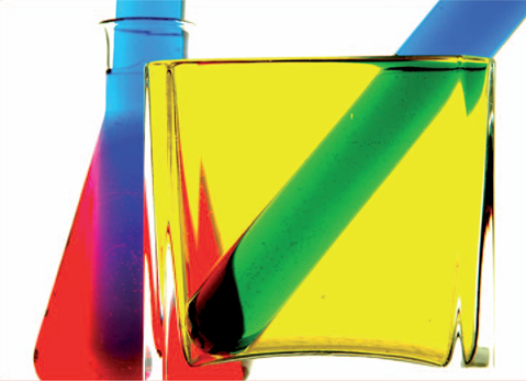
Photograph by Professor Glenn C. Miller, Imaging and Photographic Technology, Rochester Institute of Technology.
How Do Filters Work?
When light falls on a surface it can be reflected, absorbed, or transmitted. A common mnemonic used to remember these is RAT (see Figure 8-1). An object, such as a ball, will reflect the light that strikes it, whereas a stain glass window will do all three, reflect, absorb, and transmit the light that strikes it. The perceived color of any object depends upon the spectral quality of the reflected or transmitted light by that object. When illuminated with white light, an opaque white object will appear white because the surface reflects a high proportion of the incident light at all wavelengths. A black object will appear black because it reflects only a small proportion of the incident light at all wavelengths. In contrast, a red object appears red when illuminated with white light because it selectively absorbs most of the blue and green parts of the white light and reflects most of the red part. Although it will be necessary to consider what happens to the incident light wavelength by wavelength, for now it is sufficient to think in terms of the additive primary colors of light—red, green, and blue—and the additive secondary colors (or the subtractive primary colors)—cyan, magenta, and yellow.
Photographic filters function by removing part of the incident radiation by absorption or reflection, so that the transmitted radiation is of the desired spectral quality. So a green filter will pass green radiation and absorb red and blue radiation (Figure 8-2).

Figure 8-1 Light falling on a surface can be reflected (A), absorbed (B), or transmitted (C).

Figure 8-2 A green filter appears green to the eye because the filter absorbs the red and blue components of white light and transmits the green.

Figure 8-3 The blue light has no red component and therefore will not pass any light to the eye.
Filters work by removing some of the entering light.
Additive primary colors: red, green, and blue
A color filter transmits light of its own color and removes other colors of light.
Filters, of course, cannot add anything to the incident radiation—a red filter cannot transmit red light if there is no red light in the radiation falling on the filter. If a red filter is illuminated with blue radiation, no light will be passed through the filter (Figure 8-3).
Filters can be classified in a variety of ways, but with respect to the effect they have on the incident radiation there are three basic categories. They can be selective by wavelength, thus removing specific wavelengths of radiation, such as with color filters. They can be non-selective by wavelength, such as a neutral density filter that reduces the amount of radiation evenly across all wavelengths. Finally, filters can be selective by angle of polarization, as with a polarizing filter.
Color Filters
Color filters are commonly identified by the perceived color of the transmitted light when illuminated by white incident light (see Figure 8-2). For example, a red filter transmits red light and absorbs green and blue light. Color filters differ with respect to (a) which part of the visible spectrum is transmitted freely (identified by color hue or peak transmittance wavelength); (b) the width of the region transmitted and the sharpness of the cutoff (identified by a general description such as narrow, sharp-cutting bandpass or specific bandpass data); and (c) the degree of absorption of the unwanted colors (identified by general terms such as light yellow and dark yellow, or specific transmittance and density data).
Contrast filters are deep or saturated color filters that almost completely absorb the unwanted colors of light, and are commonly used in black-and-white photography to lighten or darken selected subject colors. Photographers need to be able to predict the effect that such filters will have on subject colors. One method is to look at the subject through the filter and observe which colors are lightened and which are darkened. Accuracy of this process depends upon the film and the eye responding similarly to subject colors. Although panchromatic film and the eye do not respond identically, the responses are sufficiently close to make this a valid procedure.
The Maxwell triangle (containing the three additive primary colors—red, green, and blue; and the three additive secondary colors—cyan, magenta, and yellow) can be used to predict the effect of contrast filters on black-and-white photographs without looking through the filters (see Figure 8-4). The general
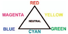
Figure 8-4 The Maxwell triangle can be used to predict the effect of contrast color filters on black-and-white photographs.

Figure 8-5 Image B is a black-and-white version of image A. Image C is taken through a yellow filter. It can be seen that the yellow in the image was lightened as was the red which is adjacent to yellow in the Maxwell triangle.
rule is that a filter will lighten subject colors that are the same color as the filter or are adjacent to that color in the triangle (see Figure 8-5). Thus a red filter will lighten red, magenta, and yellow subject colors in the print, and will darken the opposite color, cyan, and its adjacent colors, blue and green. Note that to lighten yellow and darken red simultaneously, it would be necessary to use a green filter (which is adjacent to yellow but is not adjacent to red in the triangle).
Filter factors are different for daylight and tungsten illumination.
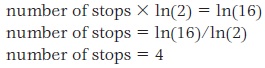
A filter factor of 16 corresponds to a 4-stop change in exposure.>
A filter will absorb light making it necessary to adjust the camera exposure to avoid under exposure. The filter factor is a multiplying number that specifies the change in exposure necessary to obtain the same density in a neutral subject area with the filter as without. Table 8-1 provides a list of filter factors and the number of stops they translate to.
The relationship between filter factor and the required number of stops the exposure must be adjusted by is defined by the following relationship, 2number of stops = filter factor. So for example, if the filter being used has a filter factor of 16, the number of stops to increase the exposure by can be found by solving the above equation as follows:
Table 8-1 Filter factor and corresponding number of stops necessary to increase exposure
| Filter Factor | Number of stops |
| 1 | 0 |
| 1.3 | 1/3 |
| 1.4 | 1/2 |
| 1.5 | 2/3 |
| 2 | 1 |
| 2.5 | 1 1/3 |
| 3 | 1 2/3 |
| 4 | 2 |
Take the natural log (ln) of each side of the equation
A second method, and perhaps easier method, is to divide the logarithm of the filter factor by 0.3. (Recall that 0.3 in neutral density is the equivalent of a one-stop change in exposure). Continuing from the above example with a filter factor of 16

If the filter factor adjustment is being applied to the exposure time without a filter, the new exposure time is found by simply multiplying the original exposure by the filter factor. For example, with an initial exposure time of 1/500 second and a filter factor of 16 the new exposure time 1/500 * 16 _ 1/30. If the filter factor must be applied to the aperture, it is important to remember that opening the diaphragm by 1 stop doubles the exposure. Continuing with the above example, for a filter factor of 16 the lens would need to be opened up by 4 stops. If the initial ƒ-stop was f/8, applying the filter factor the new f-stop would be f/2.
The published filter factor may not always produce the optimum results as factors such as the type of film and development used or the sensitivity of the digital sensor can affect the outcome. This is one reason manufacturers commonly indicate that published filter factors should be modified by the photographer if they do not produce satisfactory results. Two other aspects of the photographic process that must be taken into account in determining filter factors are the color quality of the illumination and the color sensitivity of the photographic material or digital sensor. Red filters, for example, have larger filter factors with daylight illumination than with tungsten illumination because they absorb a larger proportion of the bluer daylight illumination. Conversely, blue filters have smaller factors with daylight.
An advantage claimed by manufacturers of some cameras having behind-the-lens exposure meters is that the meter automatically compensates for the decrease in the amount of light that reaches the film or sensor when a filter is added. These claims are valid to the extent that the spectral response of the meter corresponds to the spectral sensitivity of the light sensitive material used in the camera. Some difficulty has been experienced in producing meters that have high overall sensitivity as well as the desired spectral response characteristics. A meter with high red sensitivity, for example, will give a false high reading, leading to underexposure when a red filter is used, and a false low reading, leading to overexposure when a blue filter is used.
A simple experiment can be conducted to determine the accuracy of a camera meter with filters. A neutral test card is metered with and without the filters, and the indicated changes in exposure are compared to the published filter factors. Or a gray scale is photographed with and without the filters as the camera meter indicates, and the densities or digital counts of the resulting images are compared.
The objective of the filter factor is to record neutral colors with the same density when the filter is used that they had when it was not used. With this in mind, let's examine why a filter will lighten its own color and those adjacent to it on the Maxwell triangle and darken the others. See Figures 8-4
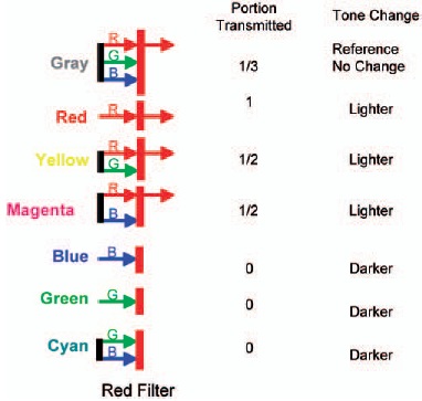
Figure 8-6 A red filter will transmit one-third of white light. The filter will lighten subject colors (in the print) while it transmits more than one-third of the light from the subject and darken subject colors when it transmits less than one-third of the light.
and 8-6. If the light that is reflected from each object is the total amount of light striking the red filter, assume that it is one unit of light. For a gray object, there are equal amounts of red, green and blue light, however only 1/3 of the total light, the red portion, is passed by the filter. The tone of this object in the final image will not change because the filter factor is applied properly to the exposure. The red object and the two objects whose colors are adjacent to the red object on the Maxwell triangle will be lightened because only a portion of the light is transmitted by the red filter. The remaining cyan, blue and green objects will be darkened because none of the light reflected from them is transmitted by the red filter.
Applying this back to black-and-white photographs created from film the lightening and darkening effects of contrast filters are often not as dramatic as photographers would like. The reason being that subject colors are seldom limited to such a narrow range of wavelengths that the light reflected from the subject is either completely absorbed or completely transmitted by contrast filters as in the example above. Less saturated color filters are produced, however, for situations where more subtle tone changes are desired. For example, a red contrast filter will considerably darken blue sky on a clear day in a black-and-white photograph. A yellow contrast filter will not have as great an effect because the ‘"blue" sky actually contains some green, which is not absorbed by the yellow filter. Subtler darkening can be obtained by switching from a contrast or deep yellow filter to a medium yellow or a light yellow filter.
Aerial haze results mostly from the scattering of light and ultraviolet radiation.
Panchromatic films used without a filter tend to record blue sky as a little lighter than it appears to the eye due to the ultraviolet radiation in blue skylight, to which films are sensitive, and the slightly high blue sensitivity of panchromatic films with daylight illumination. Panchromatic films, therefore, produce a more realistic reproduction

Figure 8-7 Both photographs were made on black and white infrared film. The photograph on the right was exposed through a red filter, which transmits red light and infrared radiation but absorbs blue and green light, to which the film is also sensitive. The photograph on the left was made without a filter.
of the lightness of subject colors when used with a light yellow filter than when used without a filter. The recommended yellow filter is classified as a correction filter. With tungsten illumination, panchromatic films tend to record reds and blues too light, so a light green filter is used as a correction filter.
Ultraviolet and Infrared Filters
The silver halides in photographic films are inherently sensitive to ultraviolet radiation and they can be made sensitive to infrared radiation through the use of sensitizing dyes. When the objective is to make a photograph solely with ultraviolet or infrared radiation, a filter is needed that transmits the desired radiation but does not transmit unwanted radiation such as white light. Some UV and IR filters are therefore visually opaque, or nearly so. IR filters are usually used in front of the camera lens so that the film is exposed solely with IR radiation (see Figures 8-7 and 8-8). If the objective is to make surreptitious photographs at night, however, the filter can be used over the flash or other source of infrared radiation so that little or no light is transmitted.
In distant outdoor scenes, ultraviolet radiation often has a deleterious effect on photographs because short-wavelength radiation is scattered much more by the atmosphere than longer-wavelength radiation, creating the appearance of haze, which obscures detail. This Rayleigh scattering, as it is called, is inversely proportional to the fourth power of the wavelength of the radiation. To reduce the appearance of haze, a filter should be used that absorbs UV radiation, as well as blue and green light. Thus a red filter effectively reduces the appearance of haze with panchromatic films, and the effect is even more dramatic when the photograph is made with IR film and IR radiation.
CCD and CMOS sensors in digital camera are sensitive to IR radiation. Many manufactures place an IR cut-off filter internal to the camera to block the cameras sensitivity to this type of radiation. This removes the ability to use a digital camera for IR photography. These filters are not meant to be removed, however a few short minutes on the internet will lead any enterprising photographer to many sites that will provide information as to how to remove these filters. Recently, some digital cameras have come to market that have IR capability such as the IS Pro by Fuji film.
Ultraviolet filters are also often used to block UV radiation in both film and digital photography. Using a UV filter will also darken blue skies and remove some of the effects of aerial haze. Both CMOS and CCD sensors are very sensitive to UV radiation. Manufacturers place filters over the sensor to block most of the UV radiation reaching the sensor; otherwise the exposure and color balance would be affected. Most camera manufacturers do not publish information on the type of internal filtering they employ in their camera designs. This means some testing with and without a UV filter is warranted. Also, many photographers use the UV filter as a protection for the camera lens. It is much more economical to replace a scratched filter than a scratched lens.
Ultraviolet radiation causes certain substances to fluoresce, whereby invisible UV radiation is converted to longer-wavelength visible radiation, revealing useful information about the material (see Figures 8-9 and 8-10). The fluorescent effect may be obscured, however, if the object is also being illuminated
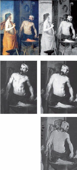
Figure 8-8 (Top left) Photograph of an oil painting. (Top right) Photograph made with black-and-white infrared film and an 87C filter over the camera lens, reveals a somewhat different original painting. The sketch on the right shows the visible image with dotted lines and the differences revealed by the infrared film with solid lines. (Photographs by Andrew Davidhazy.)
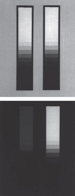
Figure 8-9 A step tablet was printed on a photographic paper containing a fluorescent brightener and on a non-brightener paper. Under tungsten illumination, which contains little ultraviolet radiation, the two prints appear similar (top). With ultraviolet radiation there is a dramatic difference in the appearance of the two.
with white light from another source. It is common practice, therefore, in fluorescence photography to use two UV filters, one that transmits only UV radiation (known as an exciter filter) over the radiation source, and another that transmits light but absorbs UV radiation(known as a barrier filter) over the camera lens so that the film records only the visible fluorescence.
Fluorescent materials convert invisible UV radiation to longer wavelength light.
Filters for Color Photography
Red, green, and blue contrast filters can be used for color photography as well as for black-and-white photography, for example, to make separation negatives from an original scene with a camera or from a color transparency with an enlarger, and to do tricolor printing with color printing paper. More widely used, however, are less-saturated filters to alter the color temperature of the illumination and to alter the color balance of transparencies and prints. If a photographer wants to use a tungsten-type color film (which is designed to be used with illumination having a color temperature of 3200 K) with daylight illumination having a color temperature of 5500 K, it is necessary to use an orange filter that will lower the color temperature of the light from 5500 K to 3200 K. Conversely, to use a daylight-type color film indoors with studio lights having a color temperature of 3200 K, it is necessary to use a bluish filter that will raise the color temperature of the light from 3200 K to 5500 K. Such filters are identified as conversion or light balancing filters.
The use of color filters for illumination color correction in digital photography presents a unique situation. Digital SLR cameras come with on-board color balancing software. The photographer can choose the preset illuminants such as tungsten or fluorescent and the resulting image should have the correct color balance. Often this can cause a loss in the dynamic range and color fringing in the image as the color corrections are done in software after the image is captured. In many situations

Figure 8-10 Ultraviolet and infrared radiation can sometimes reveal information that cannot be seen or photographed with white light. The water-damaged letter on the left was not legible under normal viewing conditions. The faded lettering, however, fluoresced in the infrared region when illuminated with white light, producing a legible copy when photographed on infrared film with a filter. (Photographs by Andrew Davidhazy.)
the loss in dynamic range may be acceptable and unnoticeable, but not always. To avoid this, the camera can be left in the daylight setting, which is the default for most cameras, and the color temperature of the light source balanced back to daylight using the same methods and filters as with film photography.
Color-compensating (CC) filters are designed to absorb any of the six additive and subtractive primary colors— red, green, blue, cyan, magenta, and yellow. Thus a red CC filter will absorb green and blue light, whereas the complementary color cyan filter will absorb only red light. Color-compensating filters are used on cameras and enlargers to control the color balance of color photographs for the purpose of compensating for variability in any part of the process including the photographic material, the illumination, and the processing—or to create mood or other special effects. CC filters are produced in a range of saturations in each of the six hues, with the saturations calibrated in terms of peak density. Thus a CC30M filter is a magenta color-compensating filter with a density of 0.30 (the decimal is omitted in the designation). Filters are available in densities ranging from 0.025 to .050.
The density of CC filters is based on the maximum absorption, not the proportion, of white light that is absorbed. For this reason, exposure corrections are not derived directly from the density but instead are obtained by trial and error, from the manufacturer's data sheet, or by measuring the transmitted light with a meter having appropriate response characteristics. A manufacturer's data sheet for example, suggests a two-thirds stop exposure increase for CC30 filters in all hues except yellow, which is one-third stop.
CC20M + CC20M = CC40M
CC20M + CC20Y = CC20R
Spectrophotometers measure the transmittance of filters wavelength-by-wavelength throughout the spectrum.
Even though contrast filters are never sandwiched, because theoretically no light would be transmitted through most combinations, such as red and green, CC filters can be combined to obtain almost unlimited control over the color quality of the image-forming light. When two or more CC filters of the same hue are combined, the densities are additive. The combined density of a CC20M filter and a CC30M filter is the same as the density of one CC50M filter, although it is necessary to increase the exposure by approximately 10% for each additional filter to compensate for light lost caused by surface reflection.
The situation is different when filters of different hues are combined. Sandwiching any two of the three subtractive primary hues—cyan, magenta, and yellow—produces the same effect as a single filter of the resulting additive primary hue and the same density. Thus, CC20M plus CC20Y filters are equivalent to one CC20R filter. Combining equal densities of all three of the subtractive primary hues results in neutral density. Thus, CC20M plus CC20Y plus CC20C is equivalent to a neutral-density filter with a density of 0.20. Combining complementary hues produces the same result; for example, CC20Y plus CC20B is equivalent to a neutral-density filter with a density of 0.20. When three or more CC filters are combined, as in color printing, it is usually better to eliminate any neutral-density combinations unless the resulting shorter exposure time would be inconveniently short.
Note that combining two of the additive primary hues is not exactly equivalent to using one filter of the corresponding subtractive primary hue. For example, combining equal densities of red and green results in a greater absorption of blue, as with a single yellow filter, but there is also a neutral-density effect because the red filter absorbs blue and green, and the green filter absorbs blue and red.
Spectrophotometric Absorption Curves
The general type of filter data discussed above is usually sufficient to meet the needs of most photographers. However, when more specific information is required for technical and scientific applications, spectrophotometric curves that show the absorption characteristics of filters throughout the spectrum are useful. In the spectrophotometer, white light is dispersed to form a spectrum. A narrow slit permits the measurement of the transmittance of a filter to a narrow band of wavelengths as the spectrum is scanned from the short-wavelength ultraviolet radiation through the visible region to the long-wavelength infrared radiation. Since the transmittance is based on a comparison of the transmitted beam to the unfiltered reference beam, the specific response characteristics of the sensor are unimportant as long as it responds to the full range of wavelengths of interest.
Spectrophotometric curves typically represent wavelengths on the horizontal axis and transmittance and density values on the vertical axis, with the baseline representing 100% transmittance, or a density of 0. As illustrated in Figure 8-11, the transmittance scale on the vertical axis is a ratio scale, which provides uniform values for the smaller divisions.
Curves for red, green, and blue tricolor contrast filters are shown in Figure 8-11. The maximum transmittance (minimum density) is in the wavelength region that identifies the hue of the filter. It can also be seen that the curves do not neatly divide the visible spectrum into thirds (it is impossible to obtain colorants that have perfectly sharp-cutting characteristics at the desired wavelengths), and that all of the filters transmit infrared radiation freely. Infrared radiation transmittance is of little consequence with respect to tone reproduction if the photographic material or digital sensor is not sensitive to infrared radiation.

Figure 8-11 Spectrophotometric curves for blue, green, and red tricolor contrast filters.
Furthermore, the curves reveal that some filters do not transmit their own colors freely. The red filter comes the closest to the ideal with a maximum transmittance of more than 90% in the red region beyond 630 nm. The blue filter has a maximum transmittance of approximately 50% to blue light, and the green filter has a maximum transmittance of only 40% to green light. It is difficult to obtain colorants with all of the desired characteristics for use in filters and in color films. Color masking, which is used in negative color films and in some color-printing processes, is necessitated by the unwanted absorption of certain colors of light by the cyan and magenta image-forming dyes.
Neutral-Density Filters
Neutral-density (ND) filters are used to reduce the illuminance by a known factor in cameras and other optical systems. The intent is to have the same transmittance for all wavelengths of radiation within specified limits. ND filters are usually calibrated in terms of white-light density. A filter with a neutral density of 0.3 has an opacity and filter factor of 2 (the antilog of 0.3) and a transmittance of 1/2 (the reciprocal of the opacity). Some ND filters have been calibrated in terms of stops, where each 0.3 in density corresponds to one stop. ND filters offer an alternative method of controlling exposure when the conventional aperture and shutter controls are inadequate. With highly sensitive photographic materials, a combination of the smallest diaphragm opening and the highest shutter speed may result in overexposure at high illumination levels. There are also situations in which the diaphragm opening is selected to produce a certain depth of field and the shutter speed is selected for a certain action stopping capability rather than for exposure considerations. With some motion-picture cameras, the shutter setting is not a useful exposure control.
0.30 neutral density = 1 stop 0.15 neutral density = 1/2 stop 0.10 neutral density = 1/3 stop
Density = log(Opacity) Transmittance = Transmitted Light/ Incident Light Opacity = 1/Transmittance
ND filters provide a convenient method of obtaining accurate small decreases in exposure. A 0.1 ND filter reduces the illuminance by the equivalent of one-third stop, 0.15 corresponds to one-half stop, and 0.2 corresponds to two-thirds stop.
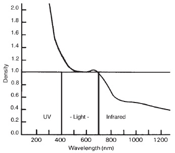
Figure 8-12 Gelatin neutral density filters containing dyes and finely divided carbon absorb too much blue light and ultraviolet radiation and too little infrared radiation.
The gelatin in gelatin filters absorbs UV radiation but transmits light and infrared radiation freely.
Pinhole cameras have no lenses and can be used to record ultraviolet radiation.
Most gelatin neutral-density filters absorb a little blue light and therefore appear slightly yellowish.
In black-and-white photography, a ND filter need not be entirely neutral with respect to the absorption of the different colors over the visible part of the spectrum. The relatively low-priced gelatin ND filters, which use carbon and dyes as light-absorbing materials, absorb somewhat more in the blue region (see Figure 8-12).
A more dramatic deviation from neutrality is noted in the ultraviolet region below 400 nm, where the density increases, and in the infrared region above 700 nm, where the density decreases. Clear gelatin and glass absorb considerable ultraviolet radiation. Thus, the gelatin in the ND filter and in the photographic emulsion if using film, and the glass lens in the camera or enlarger, absorb some (but not all) UV radiation. When photographs are to be made entirely with UV radiation, special precautions must be taken to minimize this absorption in the optical system, such as by substituting a quartz lens and avoiding use of gelatin and glass filters.
On the other hand, when UV radiation interferes with obtaining the desired effect, as in color printing, a special filter may be required to completely absorb the unwanted UV radiation. The excess IR radiation transmitted through ND filters will have no effect on light-sensitive materials that are not sensitive to these wavelengths, but it can introduce exposure errors if the exposure is based on meter readings made with a meter that is sensitive to IR radiation.
Some of the absorbing materials other than dyes that are used in ND filters include carbon, finely divided particles of photographic silver, and thin layers of metallic alloys deposited on a transparent base by evaporation in a vacuum. Colloidal carbon used in gelatin ND filters is somewhat yellowish, requiring the addition of dyes to reduce the deviation from neutrality. Larger carbon particles are more nearly neutral, but they scatter the light more, so these filters are not suitable for use in imaging systems.
The color of finely divided particles of silver depends upon their size. Most black-and-white negatives appear quite neutral in color, but negatives made on fine-grained film developed in a fine-grain developer appear somewhat warmer in color. Even smaller particles of colloidal silver function as an efficient yellow filter in the Carey-Lea filter layer, used in color films to prevent blue light from reaching the green-blue and red-blue sensitive layers.
Graduated Neutral Density Filters
The graduated neutral density filter is a filter that is used mostly in outdoor photography when the dynamic range between the sky and the earth is greater than the dynamic range of the digital sensor or film. The filter is clear on the bottom half and has neutral density across the top half. They are straight across the middle where the transition from no neutral density to neutral density takes place. This allows the photographer to capture detail in both the sky and the ground with one exposure. See Figure 8-13.
Interference Filters
Traditionally, photographic filters have consisted of colorants that absorb the unwanted part of the incident radiation and transmit the desired part, suspended in transparent materials. Interference filters typically consist of thin layers of metallic alloys separated by thin layers of transparent dielectric materials. In these layers the refractive indexes and thicknesses are controlled so that constructive and destructive interference separates the wanted and unwanted components of the incident radiation by means of reflection and transmission (see Figure 8-14).

Figure 8-13 Example of a graduated ND filter.
Reflections viewed at an angle of 35° to nonmetallic surfaces can be eliminated with a polarizing filter.
Interference filters reflect, rather than absorb, unwanted light.
Polarizing Filters
A ray of ordinary light can be visualized as consisting of waves that undulate in all directions perpendicular to the line of travel. Under certain conditions the light can become plane polarized so that there is only one set of waves, and the undulation is restricted to a single plane—like that produced in a rope when one end is snapped up and down. Polarization occurs, for example, when light is reflected as glare at an appropriate angle from most nonme-tallic surfaces. The angle at which the polarization is at a maximum varies somewhat with the reflecting material. For precision work, this angle—called the Brewster angle or the polarizing angle—can be determined from Brewster's law, which states that the tangent of the angle equals the index of refraction of the reflecting
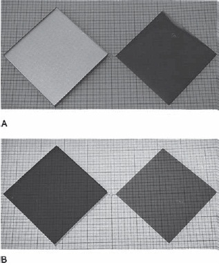
Figure 8-14 A dichroic filter (left) and a gelatin filter (right) were placed on a translucent grid on an illuminator. With the room lights on and the illuminator off, the dichroic filter looks like an opaque mirror (top left). With the room lights off and the illuminator on, the transparency of both filters is evident (bottom).
material. For example, if the glass in a window has an index of refraction of 1.5, the tangent of the polarizing angle equals 1.5, and the angle equals the inverse tangent of 1.5 or 56°.
In optics, angles of incidence and reflection are measured to the normal, a line perpendicular to the surface. When eliminating reflections in practical picture-making situations, it may be more convenient to measure the angle of reflection to the surface, which in this example would be 90° - 55° = 35° (see Figure 8-15). Because the polarizing angle does not vary greatly with the different reflecting materials ordinarily encountered, and the polarizing effect decreases gradually with deviations from the polarizing angle, an angle of 35° to the surface is commonly used.

Figure 8-15 Orientation of camera and illumination.

Figure 8-16 A reflection of a textured surface on a window obscures the object behind the window (A). Rotating a polarizing filter in front of the camera lens provides control over the reflection, which is reduced in photograph B and almost entirely eliminated in photograph C.
An artificial method of polarizing light is to pass ordinary light through a polarizing filter, which contains very small crystals all oriented in the same direction. The crystals transmit light waves oriented in the same direction and absorb light waves oriented at right angles—thus the transmitted light is plane polarized. Placing a polarizing filter in front of the eye or camera lens and rotating it to the proper position will absorb the polarized light of glare reflections from nonmetallic surfaces at an angle of approximately 35° to the surface. Therefore, the detail that had been obscured by the reflection can be seen and photographed (see Figure 8-16).
Figure 8-15 illustrates the proper camera and subject orientation to use when dealing with reflective surfaces. The orientation changes if the goal is to darken the sun (see Figure 8-17). To achieve this, point an index finger toward the sun and extend the thumb out to ninety degrees. The camera should point in the direction of the thumb to achieve the darkest sky possible.
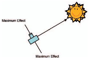
Figure 8-17 Camera and sun orientation for darkening the sky.
The two types of polarizing filters are linear and circular. Most SLR cameras and all digital SLR camera that have through-the-lens metering will require the use of a circular polarizer. These cameras use a beam splitter to achieve the metering and require a circular polarizer to function properly. A polarizing filter will reduce the reflection from glass and non-metallic reflective surfaces, darken blue sky, and increase contrast and color saturation.
Under controlled lighting conditions in-doors, glare reflections can be removed from both metallic and non-metallic surfaces with the camera at any angle to the surface provided the subject is illuminated with polarized light (by placing a polarizing filter in front of the light source) in addition to using a polarizing filter on the camera (see Figure 8-18). With polarizing filters over the light sources, surface glare reflections consist entirely of polarized light and thus can be removed with the camera filter; the polarized light that penetrates the surface, however, becomes depolarized and thus can be used to record the detail under the reflections. Polarized light is commonly used in copying textured surfaces, such as oil paintings. The filter on the camera must be rotated at a right angle to the direction of rotation of the filters in front of the light sources.
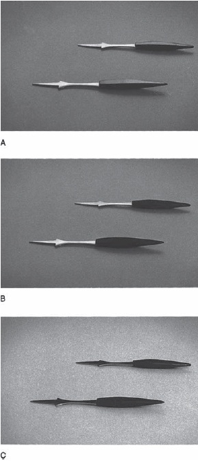
Figure 8-18 A single polarizing filter on the camera lens can eliminate the reflections on the black plastic parts of these objects because the camera angle to the reflecting surfaces is approximately 35°, but the filter has no effect on the reflections on the metal parts (B). When a polarizing screen is placed in front of the light source producing the reflections so that the reflection on the metal consists of polarized light, the filter on the lens can remove the reflections (C).
Crossed polarizing filters can be used to reveal stress patterns in transparent plastic items by placing the objects between the two filters, using transillumination. The stress patterns are revealed as areas of varying colors and densities (see Figure 8-19). A similar technique is used in photomicroscopy to reveal the structures of crystalline materials.

Figure 8-19 A plastic compact flash card was placed on a large polarizing filter on an illuminator. A second polarizing filter was rotated 90 degrees and placed on, leaving the right end uncovered. Stress patterns in the plastic are revealed as areas of varying colors. (Photography by Jessica Peterson, Biomedical Photographic Communications student, Rochester Institute of Technology.)
REVIEW QUESTIONS
- A yellow object appears yellow when viewed with white light because the object …
- reflects 580 nanometer wavelength radiation
- absorbs light nonselectively
- reflects blue light
- absorbs blue light
- absorbs yellow light
- A practical use for the Maxwell triangle is to …
- determine how many different hues there are in white light
- determine how many primary colors there are in white light
- predict the effect filters will have on photographic exposure
- predict the effect filters will have on contrast index
- predict the effect filters will have on color reproduction
- In terms of the final black-and-white photographic print, a red filter used on the camera should darken …
- cyan, magenta, and yellow objects
- red, yellow, and magenta objects
- white, gray, and black objects
- cyan, blue, and green objects
- red, green, and blue objects
- A filter factor of 8 corresponds to a change in exposure of …
- one stop
- two stops
- three stops
- four stops
- five stops
- The maximum reduction in the appearance of haze occurs when the image is recorded entirely with …
- ultraviolet radiation
- blue light
- green light
- red light
- infrared radiation
- The color of the recommended filter for use with tungsten-type color film and daylight illumination is …
- orange
- blue
- green
- cyan
- Superimposing a CC05R filter and a CC30R filter is equivalent to a single
- CC15R filter
- CC25R filter
- CC35R filter
- CC150R filter
- None of the above
- Superimposing a CC20Y filter and a CC20M filter is equivalent to a single
- CC10R filter
- CC20R filter
- CC40R filter
- ND 0.20 filter
- ND 0.40 filter
- To eliminate reflections when copying an oil painting, with the camera axis perpendicular to the surface of the painting, it is necessary to use …
- two polarizing filters in front of the camera lens
- a polarizing filter in front of each light source
- a polarizing filter in front of each light source and a polarizing filter in front of the camera lens
- A neutral density filter used with color film could cause a shift in the …
- red direction
- green direction
- blue direction
- yellow direction