
4
Setup for Success
In This Chapter
![]() Developing a setup strategy
Developing a setup strategy
![]() Starting new drawings
Starting new drawings
![]() Setting up model space
Setting up model space
![]() Creating and using drawing templates
Creating and using drawing templates
The good news is that AutoCAD is extremely powerful and versatile. And the not-quite-so-good news is that it’s extremely powerful and versatile. This means that you can set it up to work in virtually any segment of virtually any industry or application, virtually anywhere in the world. AutoCAD is used for mechanical design, electrical and electronic circuit schematics, hydraulics, buildings, bridges, theatre stage layouts, cloth-cutting layouts in the clothing industry, designing big floppy clown shoes, keeping track of season’s ticket holders’ seats in a hockey arena, and so on. In short, everything from autos to zoos.
Because most companies and schools will already have set things up to suit their particular standards, all you need to do — and in fact, must do — is to use their existing template files. If you’re working alone, however, you should read on.
In the long (or even medium or short) term, AutoCAD is much easier to use when you start from a drawing that’s set up properly. There can be quite a few things to set up, but the good news is that if you do things properly, you need to do them only once.
Sloppy setup really becomes apparent when you try to plot (note that CAD geeks say, “Plot,” whereas normal people say, “Print”) your drawing. Things that seemed more or less okay as you zoomed around on the screen are suddenly the wrong size or scale on paper. Chapter 16 covers plotting, but the information in this chapter is a necessary prerequisite to successful plotting and sheet setup. If you don’t get this stuff right, there’s a good chance you’ll find that the plot sickens.
This chapter describes the decisions you need to make before you set up a new drawing, shows the steps for doing a complete and correct setup, and demonstrates how to save setup settings for reuse.
 Don’t assume that you can just create a new blank DWG file and start drawing things. Do read this chapter before you wander too far away from this book. Many AutoCAD drawing commands and concepts depend on proper drawing setup, so you’ll have a much easier time drawing and editing things after you do your setup homework.
Then, after you digest the detailed drawing setup procedures described in this and the following chapters, use the AutoCAD Drawing Setup Roadmap on the Cheat Sheet as a quick reference to guide you through the process.
A Setup Roadmap
Before you start the drawing-setup process, you need to make only two initial decisions about your new drawing:
![]() What system of measure — metric or Imperial — will you use?
What system of measure — metric or Imperial — will you use?
![]() What drawing units will you use?
What drawing units will you use?
Choosing your units
AutoCAD is extremely flexible about drawing units; it lets you have them your way. Usually, you choose the type of units that you normally use to talk about whatever you’re drawing: feet and inches for a building in the United States, millimeters for a metric screw, and so on.
Speaking of millimeters, here’s another choice you have to make even before you choose your units of measure — and that’s your system of measure.
Most of the world abandoned local systems of measure generations ago. Even widely adopted ones, like the Imperial system, have mostly fallen by the wayside (just like their driving force, the British Empire) — except, of course, in the United States, where feet, inches, pounds, gallons, and degrees-Fahrenheit still rule.
During drawing setup, you choose settings for length units (for measuring linear objects and distances) and angle units (for measuring angles between nonparallel objects or points on arcs or circles) in the Drawing Units dialog box, as shown in Figure 4-1. (We show you how to specify these settings in the section “Setting your units,” later in this chapter.) AutoCAD’s length unit types are as follows:
![]() Architectural units are based in feet and inches and use fractions to represent partial inches: for example, 12'3 1/2". The base unit is the inch unless otherwise specified, so if you enter a number like 147.5, then AutoCAD will understand it to be 12'3 1/2".
Architectural units are based in feet and inches and use fractions to represent partial inches: for example, 12'3 1/2". The base unit is the inch unless otherwise specified, so if you enter a number like 147.5, then AutoCAD will understand it to be 12'3 1/2".
![]() Decimal units are unitless — that is, they’re not based on any particular real-world unit. With decimal units, each unit in the drawing could represent an inch, a millimeter, a parsec, a furlong, a fathom, a cubit (if you’re into building arks in case that rainy day should come), or any other unit of measure you deem suitable, from Danish alens to the Swiss zoll. An example would be 15.5.
Decimal units are unitless — that is, they’re not based on any particular real-world unit. With decimal units, each unit in the drawing could represent an inch, a millimeter, a parsec, a furlong, a fathom, a cubit (if you’re into building arks in case that rainy day should come), or any other unit of measure you deem suitable, from Danish alens to the Swiss zoll. An example would be 15.5.
![]() Engineering units are based in feet and inches and use decimals to represent partial inches: for example, 12'3.5".
Engineering units are based in feet and inches and use decimals to represent partial inches: for example, 12'3.5".
![]() Fractional units, like decimal units, are unitless and show values as fractions rather than decimal numbers: for example 15 1/2.
Fractional units, like decimal units, are unitless and show values as fractions rather than decimal numbers: for example 15 1/2.
![]() Scientific units, also unitless and show values as exponents, are used for drawing really tiny or really large things. If you design molecules or galaxies, this is the unit type for you. Examples would be 15.5E+06 (which is 15,500,000) and 15.5E–06 (which is 0.0000155).
Scientific units, also unitless and show values as exponents, are used for drawing really tiny or really large things. If you design molecules or galaxies, this is the unit type for you. Examples would be 15.5E+06 (which is 15,500,000) and 15.5E–06 (which is 0.0000155).

Figure 4-1: The Drawing Units dialog box.
AutoCAD’s angle unit types are as follows:
![]() Decimal Degrees show angles as decimal numbers and are by far the easiest to work with, if your type of work allows it.
Decimal Degrees show angles as decimal numbers and are by far the easiest to work with, if your type of work allows it.
![]() Deg/Min/Sec is based on the old style of dividing a degree into minutes and minutes into seconds. Seconds aren’t fine enough to display AutoCAD’s precision capabilities, though, so seconds can be further divided into decimals. There is no degree symbol on a standard keyboard, so AutoCAD uses the lowercase letter d. An example would be 45d30'10.7249". One nautical mile (6,076 feet) is approximately 1 minute of arc of longitude on the equator. David Letterman once said that the equator is so long that it would reach once around the world.
Deg/Min/Sec is based on the old style of dividing a degree into minutes and minutes into seconds. Seconds aren’t fine enough to display AutoCAD’s precision capabilities, though, so seconds can be further divided into decimals. There is no degree symbol on a standard keyboard, so AutoCAD uses the lowercase letter d. An example would be 45d30'10.7249". One nautical mile (6,076 feet) is approximately 1 minute of arc of longitude on the equator. David Letterman once said that the equator is so long that it would reach once around the world.
![]() Grads and Radians are mathematically beautiful (so we’re told) but are not widely used in drafting. Apparently, the French artillery uses grads, but as long as we’re friends with them, we shouldn’t have to worry.
Grads and Radians are mathematically beautiful (so we’re told) but are not widely used in drafting. Apparently, the French artillery uses grads, but as long as we’re friends with them, we shouldn’t have to worry.
![]() Surveyor’s Units type is similar to Deg/Min/Sec but uses quadrants (quarter circles) rather than a whole circle. An angle in Deg/Min/Sec might measure 300d0'.00", while the same angle in Surveyor’s Units would be represented as S 30d0'0.00" E.
Surveyor’s Units type is similar to Deg/Min/Sec but uses quadrants (quarter circles) rather than a whole circle. An angle in Deg/Min/Sec might measure 300d0'.00", while the same angle in Surveyor’s Units would be represented as S 30d0'0.00" E.
 The unit types you’ll most likely use are Decimal, Architectural, and Decimal Degrees. You’ll know or be told if you need to use one of the other types.
AutoCAD always works internally to something like 16-digit accuracy. Changing the type of units changes only how values are displayed, suitably rounded off. For example, a line that’s 15.472563 decimal units long would display as 12"3 1/2" long when units are changed to Architectural. The actual length — and any calculations based on it — remains at 15.472563 and does not change to 15.5".
When you use dash-dot linetypes (Chapter 10) and hatching (Chapter 14) in a drawing, it matters to AutoCAD whether the drawing uses an Imperial (inches, feet, miles, and so on) or metric (millimeters, meters, kilometers, and so on) system of measure. The MEASUREINIT and MEASUREMENT system variables control whether the linetype and hatch patterns that AutoCAD lists for you to choose from are scaled with inches or millimeters in mind as the plotting units. For both variables, a value of 0 (zero) means inches (that is, an Imperial-units drawing), whereas a value of 1 means millimeters (that is, a metric-units drawing). If you start from an appropriate template drawing (as described in the section “A Template for Success,” later in this chapter), the system variable values will be set correctly, and you won’t ever have to think about it. (For an explanation of system variables and how to set them, see Chapter 25.)
So why are there two variables? Simple. MEASUREMENT sets the default value for all new drawings, and MEASUERINIT sets the value for the current drawing.
 AutoCAD automatically sets the measurement system according to your country when it’s being installed, but it can be changed.
Weighing up your scales
Somewhat surprisingly, you don’t need to consider scale when setting up a new drawing.
“Okay,” you’re saying, “I understand that I need to print my drawings at a scale acceptable to the discipline I work in. But if I’m drawing stuff full size, when do I need to worry about the scale factor?” Grab yourself a nice mug of cocoa and settle down ’round the fire because we’re going to tell you. By now you know (because we’ve told you so) that you draw real things full size, but drawings contain other things that are not real, such as text, dimensions, hatch patterns, title blocks, dash-dot linetypes, and so forth. And those nonreal things need to be legible on your plotted drawing.
Say, for example, you draw a plan of your garage, and now you want to plot it on an 11 x 17" sheet of paper. No problem; just tell the PLOT command to scale everything down by a scale factor of 1:24, which architects would commonly represent as 1/2"=1'0".
Oops, problem. Text annotations are typically about 3/32" or 1/8" high. Now, if you draw your 6 inch–wide wall full size, put a 1/8"-high title beside it, and then print the drawing at a scale of 1:24, the wall itself will measure 1/4" on the sheet, and the note will be an illegible little speck beside it. You fix it by making the text 24 times larger, or 3 inches tall, so that it scales down to the correct size when plotted. See, sometimes two wrongs do make a right (usually it takes three, although three rights make a left).
The “Drawing scale versus drawing scale factor” sidebar explains how you arrive at the scale factor, but this isn’t an issue until it comes time to annotate your drawing. We cover noncontinuous linetype scaling in Chapter 10, text sizing in Chapter 13, dimensions in Chapter 14, and crosshatching in Chapter 15. The good news is that AutoCAD can now take care of all this automatically, but rumor has it that there may still be a few drawings out there that did it the old way, so we cover both methods in the appropriate chapters.
You shouldn’t just invent some arbitrary scale based on what looks okay on whatever size paper you happen to have handy. Most industries work with a small set of approved drawing scales that are related to one another by factors of 2 or 10. If you use other scales, at best, you’ll be branded a clueless newbie. At worst, you’ll have to redo all your drawings at an accepted scale.
Table 4-1 lists some common architectural drawing scales, using both Imperial and metric systems of measure. The table also lists the drawing scale factor corresponding to each drawing scale and the common uses for each scale. If you work in industries other than those listed here, ask drafters or co-workers what the common drawing scales are and for what kinds of drawings they’re used.
Table 4-1 Common Architectural Drawing Scales
|
Drawing Scale |
Drawing Scale Factor |
Common Uses |
|
1/16" = 1'-0" |
192 |
Large-building plans |
|
1/8" = 1'-0" |
96 |
Medium-sized building plans |
|
1/4" = 1'-0" |
48 |
House plans |
|
1/2" = 1'-0" |
24 |
Small-building plans |
|
1" = 1'-0" |
12 |
Details |
|
1:200 |
200 |
Large-building plans |
|
1:100 |
100 |
Medium-sized building plans |
|
1:50 |
50 |
House plans |
|
1:20 |
20 |
Small building plans |
|
1:10 |
10 |
Details |
After you choose a drawing scale, engrave the corresponding drawing scale factor on your desk, write it on your hand (don’t mix those two up, okay?), and put it on a sticky note on your monitor. You eventually need to know the drawing scale factor for many drawing tasks, as well as for some plotting. You should be able to recite the drawing scale factor of any drawing you’re working on in AutoCAD without even thinking about it.
Even if you’re going to use the Plot dialog box’s Fit to Paper option (rather than a specific scale factor) to plot the drawing, you still need to choose a scale to make the nonreal things (such as text, dash-dot linetypes, hatch patterns, and so on) appear at a useful size. We cover plotting in Chapter 16.
Thinking about paper
You don’t normally need to worry about the size of the paper that you want to use for plotting your drawing until much later in the drawing process. And that’s the beauty of CAD: You can easily move views around to suit after you get the basic object drawn, and you don’t need to worry about scale factors until you’re ready to add annotations. We cover this in excruciatingly more (just kidding, it’s actually quite simple) detail in Chapters 12–15. Here again, most industries use a small range of standard sheet sizes.
Here are the two ways of laying out a drawing so it’s ready to be plotted:
![]() In model space: In this process, everything was drawn in model space, which was the only known universe. The drawing was created full size, while text and dimension component sizes, hatch pattern scaling, title blocks, and borders were all created at the inverse of the final plotting scale. This was the only way for many years, so you’ll encounter many drawings that were made this way.
In model space: In this process, everything was drawn in model space, which was the only known universe. The drawing was created full size, while text and dimension component sizes, hatch pattern scaling, title blocks, and borders were all created at the inverse of the final plotting scale. This was the only way for many years, so you’ll encounter many drawings that were made this way.
![]() In paper space: Finally, Autodesk programmers figured out how to tunnel through into a parallel universe called “paper space,” which revolutionized drawing production. Current preferred practice is to draw the object in model space, cut a viewport in paper space so you can look through to the model space, and then apply documentation in paper space.
In paper space: Finally, Autodesk programmers figured out how to tunnel through into a parallel universe called “paper space,” which revolutionized drawing production. Current preferred practice is to draw the object in model space, cut a viewport in paper space so you can look through to the model space, and then apply documentation in paper space.
We cover model space versus paper space in Chapter 16.
Drafting on paper versus electronically
If you’ve ever done paper-and-pencil drafting (and there are fewer and fewer of us left who have), you’ll find that AutoCAD’s electronic paper works backward from dead-trees paper.
![]() Dead-trees paper: We used to consider the approximate size of the object that we were drawing and which views we wanted of it, selected a suitable sheet of paper from a set of standard sizes, and then scaled the drawing of the object to suit the sheet of paper. We were constantly translating sizes between the real-world object and our drawing of it. The height of text and the size of the components in dimensions were fixed. Again, scales were selected from a list of preferred values. You rarely saw a paper drawing at a scale of 1:2.732486921.
Dead-trees paper: We used to consider the approximate size of the object that we were drawing and which views we wanted of it, selected a suitable sheet of paper from a set of standard sizes, and then scaled the drawing of the object to suit the sheet of paper. We were constantly translating sizes between the real-world object and our drawing of it. The height of text and the size of the components in dimensions were fixed. Again, scales were selected from a list of preferred values. You rarely saw a paper drawing at a scale of 1:2.732486921.
![]() Electronic paper: We draw everything full size and then tell the PLOT command to stretch or shrink things accordingly. This makes it much easier because we never have to translate sizes. Admittedly, in the early days, the size of text and of the components in dimensions could get a little awkward, but Chapters 12–15 show you how AutoCAD now makes this extremely simple.
Electronic paper: We draw everything full size and then tell the PLOT command to stretch or shrink things accordingly. This makes it much easier because we never have to translate sizes. Admittedly, in the early days, the size of text and of the components in dimensions could get a little awkward, but Chapters 12–15 show you how AutoCAD now makes this extremely simple.
Defending your border
The next decision to make is what kind of border your drawing needs. The options include a full-blown title block, a simple rectangle, or nothing at all around your drawing. If you need a title block, do you have one?, can you borrow an existing one?, or will you need to draw one from scratch? Although you can draw title block geometry in an individual drawing, you’ll save time by reusing the same title block for multiple drawings. Your company or client should already have a standard title block drawing ready to use, or someone else who’s working on your project may have created one for the project.
The most efficient way of creating a title block is as a separate DWG file, drawn at its normal plotted size (for example, 36" x 24" for an architectural D-size title block, or 841mm x 594mm for an ISO A1-size version). You then insert (see Chapter 17) or xref (see Chapter 18) the title block drawing into each drawing sheet.
A Template for Success
When you start in either the Drafting & Annotation workspace (as we do throughout this book) or the old AutoCAD Classic workspace, AutoCAD creates a new, blank drawing configured for 2D drafting. Depending on where you live (your country, not your street address!) and the dominant system of measure used there, AutoCAD will base this new drawing on one of two default drawing templates:
![]()
acad.dwt for the Imperial system of measure, as used in the United States
![]()
acadiso.dwt for the metric system, used throughout most of the rest of the galaxy
In AutoCAD LT, the two default templates are acadlt.dwt and acadltiso.dwt. When you explicitly create a new drawing from within AutoCAD, the Select Template dialog box, shown in Figure 4-2, appears by default so you can choose a template on which to base your new drawing.
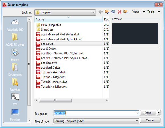
Figure 4-2: A toolbox of templates.
You may be familiar with Microsoft Word or Excel template files, and AutoCAD drawing templates work pretty much the same way because Autodesk stole the idea from them (encouraged, of course, by Microsoft, although one could argue that it was the other way around).
A template is simply a drawing whose name ends in the letters DWT, which you use as the starting point for another drawing. When you create a new drawing from a template, AutoCAD makes a copy of the template file and opens the copy in a new drawing editor window. The first time you save the file, you’re prompted for a new filename to save to; the original template file stays unchanged.
Using a suitable template can save you time and worry because many of the setup options are already set correctly for you. You know the drawing will print correctly; you just have to worry about getting the geometry and text right. Of course, all this optimism assumes that the persons who set up the template knew what they were doing.
The stock templates that come with AutoCAD are okay as a starting point, but you’ll want to modify them to suit your purposes or create your own from scratch. In particular, the stock AutoCAD templates are probably not set up for the scales you’ll want to use. The instructions in the rest of this chapter tell you how to specify scale-dependent setup information.
So, the only problems with templates are creating good ones and then later finding the right one to use when you need it. Later in this chapter, in the “Making Templates Your Own” section, we show you how to create templates from your own setup drawings. Here we show you how to use an already-created template — say, one of the templates that comes with AutoCAD 2014 or one you get from a CAD-savvy colleague. If you’re lucky, someone in your office has created suitable templates that you can use to get going quickly.
Follow these steps to create a new drawing from a template drawing:
1. Run the NEW command by pressing Ctrl+N or clicking the Application button and choosing New.
The Select Template dialog box appears.
The first button on the Quick Access toolbar runs the QNEW (Quick NEW) command instead of the ordinary NEW command. If you or someone else has changed the Default Template File Name for QNEW in the Options dialog box, QNEW will not open the Select Template dialog box; instead, it simply presents you with a new, blank drawing — possibly not the one you wanted. You can take advantage of QNEW, though. For information how, see the “Making Templates Your Own” section, later in this chapter.
2. Click the name of the template you want to use as the starting point for your new drawing and then click the Open button.
A new drawing window with a temporary name, such as Drawing2.dwg, appears. (The template you opened remains unchanged on your computer's hard drive.)
Depending on which template you choose, your new drawing may open in a paper space layout, not in model space. If that’s the case, click the Model button on the status bar before changing the settings described in the next section. (We describe how to set up and take advantage of paper space layouts in Chapter 15.)
3. Press Ctrl+S or click the Application button and choose Save to save the file under a new name.
Take the time to save the drawing to the appropriate name and location now.
4. Make needed changes.
With most of the templates that come with AutoCAD, consider changing the units, limits, grid and snap settings, linetype scale, and dimension scale. See the next section for instructions.
5. Save the drawing again.
If you’ll need other drawings in the future similar to the current one, consider saving your modified template as a template in its own right. See the section “Making Templates Your Own,” later in this chapter, for the lowdown on saving templates.
A few of the remaining templates that come with AutoCAD include title blocks for various sizes of sheets. In addition, most templates come in two versions: one for people who use color-dependent plot styles and one for people who use named plot styles. You probably want the color-dependent versions. (Chapter 16 describes the two kinds of plot styles and why you probably want the color-dependent variety.)
Making the Most of Model Space
After you decide on drawing scale and sheet size, you’re ready to set up your drawing. Most drawings require a two-part setup:
1. Set up model space, where you’ll create most of your drawing.
2. Create one or more paper space layouts for plotting.
As we explain in Chapter 2, model space is the infinitely large, three-dimensional environment in which you create the “real” objects you’re drawing. You can set up your model space as described in this section; Chapter 16 introduces you to setting up your paper space layouts.
Setting your units
Follow these steps to set the linear and angular units that you want to use in your new drawing:
1. Click the Application button and then choose Units from the Drawing Utilities group.
The Drawing Units dialog box appears, as shown in Figure 4-3.

Figure 4-3: Set your units here.
2. Choose a linear unit type from the Length Type drop-down list.
Choose the type of unit representation that’s appropriate for your work. Engineering and Architectural units are displayed in feet and inches; the other types of units aren’t tied to any particular unit of measurement. You decide whether each unit represents a millimeter, centimeter, meter, inch, foot, or something else. Your choice is much simpler if you’re working in metric: Choose Decimal units.
AutoCAD can think in inches! If you’re using Engineering or Architectural units (feet and inches), AutoCAD interprets any distance or coordinate you enter as that many inches. You must use the ’ (apostrophe) character on your keyboard to indicate a number in feet instead of inches. Using the ” symbol to indicate inches isn’t required but is acceptable.
3. From the Length Precision drop-down list, choose the level of precision you want when AutoCAD displays coordinates and linear measurements.
The Length Precision setting controls how precisely AutoCAD displays coordinates, distances, and prompts in some dialog boxes. For example, the Coordinates section of the status bar displays the current coordinates of the crosshairs, using the current precision.
The linear and angular precision settings affect only AutoCAD’s display of coordinates, distances, and angles on the status bar, in dialog boxes, and in the command line and Dynamic Input tooltip areas. For drawings stored as DWG files, AutoCAD always uses maximum precision to store the locations and sizes of all objects that you draw, regardless of how many decimal places you choose to display in the Drawing Units dialog box. In addition, AutoCAD provides separate settings for controlling the precision of dimension text. (See Chapter 14 for details.)
4. Choose an angular unit type from the Angle Type drop-down list.
Decimal Degrees and Deg/Min/Sec are the most common choices.
The Clockwise check box and the Direction button provide additional angle measurement options, but you’ll rarely need to change the default settings: Unless you’re a land surveyor, measure angles counterclockwise and use east as the 0-degree direction.
5. From the Angle Precision drop-down list, choose the degree of precision you want when AutoCAD displays angular measurements.
6. In the Insertion Scale area, choose the units of measurement for this drawing.
Choose your base unit for this drawing — that is, the real-world distance represented by one AutoCAD unit. We discuss the significance of this in Chapter 17.
 The AutoCAD (but not the AutoCAD LT) Drawing Units dialog box includes a Lighting area where you specify the unit type to be used to measure the intensity of photometric lights. We introduce lighting as part of rendering 3D models in Chapter 23.
7. Click OK to exit the dialog box and save your settings.
Making the drawing area snap-py (and grid-dy)
For the last three decades, AutoCAD’s grid consisted of a set of evenly spaced dots that served as a visual distance reference. You can still configure a dot grid, but starting with AutoCAD 2011, the default is a snazzy graph paper–like grid made up of a network of lines.
AutoCAD’s snap feature creates a set of evenly spaced, invisible hot spots, which make the crosshairs move in nice, even increments as you specify points in the drawing. Both Grid mode and Snap mode are like the intersection points of the lines on a piece of grid paper, but the grid is simply a visual reference — it never prints — whereas Snap mode constrains the points that you can pick with the mouse. You can set grid and snap spacing to different values.
You don’t have to toggle Snap mode on and off. It’s on only when you’re using a command that asks you to specify a point. For example, when Snap is on, you can move your crosshairs freely around the screen, but when you start the Line command, Snap mode kicks in, and your crosshairs jump to the closest snap point.
Set the grid and the snap intervals in the Drafting Settings dialog box by following these steps:
1. Right-click the Snap Mode or Grid Display button on the status bar and choose Settings from the menu that appears.
The Drafting Settings dialog box appears with the Snap and Grid tab selected, as shown in Figure 4-4.
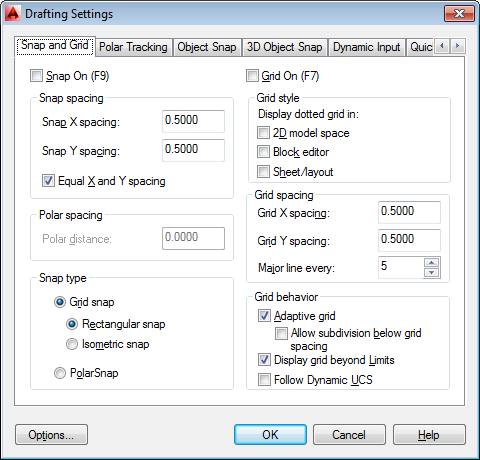
Figure 4-4: Get your drafting settings here!
The Snap and Grid tab has six sections, but the Snap Spacing and Grid Spacing areas within that tab are all you need to worry about for most 2D drafting work.
2. Select the Snap On check box to turn on Snap mode.
This action enables default snaps half a unit apart (ten units apart if you’re working with the default metric template).
AutoCAD usually has several ways of doing things. You can also click the Snap Mode button on the status bar to toggle snap on and off; the same goes for the Grid Display button and the grid setting. Or you could press the function keys: F7 toggles the grid off and on, and F9 does the same for Snap mode.
3. Enter the snap interval you want in the Snap X Spacing text box.
Use the information in the sections preceding these steps to decide on a reasonable snap spacing.
If the Equal X and Y Spacing check box is selected, the Y spacing changes automatically to equal the X spacing, which is almost always what you want. Deselect the check box if you want to specify unequal snap spacing.
4. Select the Grid On check box to turn on the grid.
5. Enter the desired grid spacing in the Grid X Spacing text box.
Use the information in the sections preceding these steps to decide on a reasonable grid spacing.
As with snap spacing, if the Equal X and Y Spacing check box is selected, the Y spacing automatically changes to equal the X spacing. Again, you usually want to leave it that way.
X measures horizontal distance; Y measures vertical distance. The AutoCAD drawing area normally shows an X and Y icon in case you forget.
If you’re an old AutoCAD hand and find the graph paper grid too obtrusive, select the Display Dotted Grid in 2D Model Space check box in the Grid Style area to switch to the old-style rows and columns of dots. Interestingly, it seems most beginners like the grid, but most experienced users turn it off.
6. Specify additional grid display options in the Grid Behavior area:
• Adaptive Grid: AutoCAD changes the density or spacing of the grid lines or dots as you zoom in and out.
• Allow Subdivision Below Grid Spacing: Select this check box in conjunction with the Adaptive Grid check box. The spacing can go lower than what you’ve set, and it may go higher if you’re zoomed a long way out of your drawing. (If it didn’t, you couldn’t see your drawing for the grid!)
• Display Grid Beyond Limits: This allows the grid to display over the entire drawing area, no matter how far you’re zoomed out. Clearing this check box makes AutoCAD behave the way it always behaved in earlier releases — that is, the grid is displayed only in the area defined by the drawing limits.
• Follow Dynamic UCS: This option (not available in AutoCAD LT) is a 3D-specific feature that changes your drawing plane as you mouse over 3D objects. We cover this feature in Chapter 21.
7. Click OK to close the Drafting Settings dialog box.
Setting linetype and dimension scales
Even if you’ve engraved the drawing scale factor on your desk and written it on your hand — not vice versa — AutoCAD doesn’t know the drawing scale until you enter it. Keeping AutoCAD in the dark is fine as long as you’re just drawing continuous lines and curves representing real-world geometry because you draw these objects at their real-world size, without worrying about plot scale.
However . . . as soon as you start using noncontinuous dash-dot linetypes (line patterns that contain gaps in them), you need to tell AutoCAD how to scale the gaps in the linetypes based on the plot scale. If you forget this, the dash-dot linetype patterns can look waaaay too big or too small. Figure 4-5 shows what we mean.
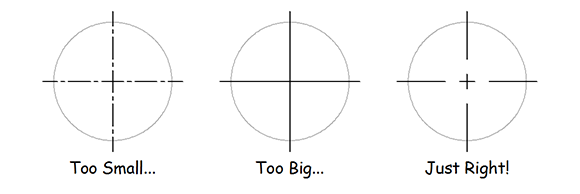
Figure 4-5: And this little center line looks juuuust right!
The scale factor that controls dash-dot linetypes is found in a system variable called LTScale (as in, LineType Scale). You can change this setting at any time, but it’s best to set it correctly when you’re setting up the drawing.
The following steps include directions for typing system variable and command names. To set the linetype scale at the keyboard, follow these steps:
1. Type LTSCALE (or LTS) and press Enter.
AutoCAD responds with a prompt, asking you for the scale factor. The value at the end of the prompt is the current linetype scale setting, as shown in the following command line example:
Enter new linetype scale factor <1.0000>:
2. Type the value you want for the linetype scale and press Enter.
The easiest choice is to set the linetype scale to the drawing scale factor. Some people, however, find that the dashes and gaps in dash-dot linetypes get a bit too long when they use the drawing scale factor. If you’re one of those people, set LTSCALE to one-half of the drawing scale factor. (Feel free to experiment with this value; some people prefer a linetype scale of three-quarters the scale factor. If you’re working in metric, try 0.75 times the scale factor instead — just ask your calculator if you don’t believe us.)
Alternatively, you can specify linetype scale in the Linetype Manager dialog box: Click the Linetype drop-down list on the Properties panel of the Ribbon’s Home tab and select Other. Then in the Linetype Manager dialog box, click the Show Details button, and type your desired linetype scale in the Global Scale Factor text box.
Besides LTSCALE, there are three other similarly named system variables you can use to control the display of dash-dot linetypes:
![]() PSLTSCALE: Makes linetype spacing look the same in paper space viewports, regardless of the viewport scale
PSLTSCALE: Makes linetype spacing look the same in paper space viewports, regardless of the viewport scale
![]() CELTSCALE: Changes the effective linetype scale factor for new objects
CELTSCALE: Changes the effective linetype scale factor for new objects
![]() MSLTSCALE: Visually displays dash-dot linetypes in the model tab based on the annotative scale setting
MSLTSCALE: Visually displays dash-dot linetypes in the model tab based on the annotative scale setting
If any of these sound useful — and we highly recommend that you enable PSLTSCALE — check them out in the online help index.
You should set linetype scale only when you're starting a new drawing from one of the generic AutoCAD templates (acad.dwt or acadiso.dwt in the full version, acadlt.dwt or acadltiso.dwt in AutoCAD LT) and you're not using the default linetype scale. Don't change LTSCALE in existing drawings without knowing exactly why you're doing it and what values to set them to, in case someone before you set those values for good reasons.
Entering drawing properties
We recommend one last bit of housekeeping before you’re finished with model space drawing setup: Enter summary information in the Drawing Properties dialog box, as shown in Figure 4-6. Click the Application button; in the Drawing Utilities section, choose Drawing Properties to open the Drawing Properties dialog box; then click the Summary tab. Enter the drawing scale and the drawing scale factor you’re using in the Comments area, plus any other information you think useful.
Don’t confuse drawing properties (which are really file properties) with your drawing’s object properties — they’re different things. The properties you enter here can help you or someone you love when she opens your drawing and wonders how you set it up. Object properties are a big enough topic to merit their own chapter. (See Chapter 9.)

Figure 4-6: Surveying your drawing’s properties.
Making Templates Your Own
You can create a template from any DWG file by using the Save Drawing As dialog box. Follow these steps to save your drawing as a template:
1. Click Save As on the Quick Access toolbar.
The Save Drawing As dialog box appears, as shown in Figure 4-7.
2. From the Files of Type drop-down list, choose AutoCAD Drawing Template (*.dwt) or AutoCAD LT Drawing Template (*.dwt).
3. Navigate to the folder where you want to store the drawing template.
The AutoCAD 2014 default folder for drawing templates is buried deep in the bowels of your Windows user profile, which by default isn’t visible in Windows Explorer. Hey, we never said this made any sense! Save your templates there if you want them to appear in AutoCAD’s Select Template list. You can save your templates in another folder, but if you want to use them later, you have to navigate to that folder every time you want to use them.
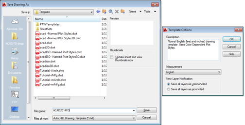
Figure 4-7: Saving a drawing as a template and applying options.
4. Enter a name for the drawing template in the File Name text box and then click Save.
A dialog box for the template description and units appears.
5. Specify the template’s measurement units (English or Metric) from the drop-down list.
Enter the key info now; you can’t do it later unless you save the template to a different name. Don’t bother filling in the Description field; AutoCAD doesn’t display it in the Select Template dialog box. Don’t worry about the New Layer Notification area shown in Figure 4-7 for now; we tell you all about drawing layers in Chapter 9.
6. Click OK to save the file.
The Template Options dialog box closes, and the template is saved to your hard drive.
7. To save your drawing as a regular drawing, click Save As on the Quick Access toolbar.
The Save Drawing As dialog box appears again.
8. From the Files of Type drop-down list, choose AutoCAD 2013 Drawing (*.dwg).
Choose the AutoCAD LT equivalent, if that’s your version. AutoCAD 2014 uses the same file format as 2013 (and 2015) that can’t be opened by earlier releases. Choose a previous DWG file format if you want to be able to open your drawing in AutoCAD 2012 or earlier, but note that some features introduced in later releases may not translate properly to earlier ones, and may not survive a round trip back into 2013 or later.
9. Navigate to the folder where you want to store the drawing.
Use a different folder from the one with your template drawings.
10. Enter the name of the drawing in the File Name text box and click Save.
The file is saved. Now, when you save it in the future, the regular file — not the template file — is updated.
Okay, do you want to know the real secret behind template files? One letter. That’s right, the only difference is that a drawing file has the extension DWG, and a template’s extension is DWT. You can convert a drawing to a template just by using Windows Explorer to change the extension. The further secret to this is that a DWT can hold any information that you can put in a DWG. For example, you may often need to produce a drawing of a new machine shaft. All details are the same as previous shafts except for the length. Draw it once and convert it to a template. Now, when you need a new shaft drawing, just start it from the shaft template, change the length, and you’re done!
The QNEW (Quick NEW) command, when properly configured, can bypass the Select Template dialog box and create a new drawing from your favorite template. The first button on the Quick Access toolbar — the button with the plain white sheet of paper — runs the newer QNEW command instead of the older NEW command.
To put the Quick into QNEW, though, you have to tell AutoCAD which default template to use:
1. Click the Application button and then click the Options button at the lower-right corner of the Application menu.
2. On the Files tab, choose Template Settings and then Default Template File Name for QNEW.
The QNEW default file name setting is None, which causes QNEW to act just like NEW (that is, QNEW opens the Select Template dialog box). Specify the name of your favorite template here, and you get a new drawing file based on it every time you click QNEW.
AutoCAD 2014 stores drawing templates and many other support files under your Windows user folder. To discover where your template folder is hiding, open the Options dialog box. On the Files tab, choose Template Settings and then Drawing Template File Location, as shown in Figure 4-8.
Finding your user folder
Microsoft insists that any program that uses files unique to or modifiable by individual users must be kept in separate a folder system for each user so that different people sharing a computer won’t mess up each other’s settings. There are just two minor flaws with this edict:
![]() Hardly anyone shares a computer these days. In fact, our tech editor claims that a typical user today has multiple computers, and brags/complains that he has three, not including Androids.
Hardly anyone shares a computer these days. In fact, our tech editor claims that a typical user today has multiple computers, and brags/complains that he has three, not including Androids.
![]() By default, this is a hidden system folder that you can’t see in Windows Explorer, making it difficult to copy, rename, or move files in it.
By default, this is a hidden system folder that you can’t see in Windows Explorer, making it difficult to copy, rename, or move files in it.
The solution:
Windows XP
1. Start Windows Explorer.
2. In its menu, click Tools then Folder Options.
3. Under the View tab, click the Show Hidden Files and Folders button and then deselect the Hide Extensions for Known File Types check box.
4. Click OK.
Windows 7
1. Start Windows Explorer.
2. Choose Organize⇒Folder⇒Search Options.
3. Under the View tab, click the Show Hidden Files and Folders button and then deselect the Hide Extensions for Known File Types check box.
4. Click OK.
Windows 8
1. In File Explorer, choose the View tab.
2. Click the Options button.
3. Follow the remaining steps as for Windows 7 (in the preceding list).
Now you can see what’s happening in your private folder.
You don't have to keep your template files where that bossy Mister Gates tells you. Create a folder that you can find easily (for example, C:Acad-templates or F:Acad-custom emplates on a network drive), put the templates that you actually use there, and change the Drawing Template File Location setting so that it points to your new template folder.
In an office environment in particular, the template folder should live on a network drive so that everyone starts from the same templates.

Figure 4-8: Seek and you shall find your template folder.