
18
Everything from Arrays to Xrefs
In This Chapter
![]() Introducing associative arrays, external references (xrefs), raster images, and dynamic blocks
Introducing associative arrays, external references (xrefs), raster images, and dynamic blocks
![]() Creating associative arrays
Creating associative arrays
![]() Attaching and managing xrefs, DWFs, and PDFs
Attaching and managing xrefs, DWFs, and PDFs
![]() Controlling xref paths
Controlling xref paths
![]() Importing other file formats
Importing other file formats
![]() Attaching and managing raster image files
Attaching and managing raster image files
![]() Authoring dynamic blocks
Authoring dynamic blocks
Simple arrays have served AutoCAD users well for many years. They’re basically just a quick way of producing multiple copies of drawing objects in regular patterns. If you’re not familiar with simple arrays, flip to Chapter 11.
Associative arrays are dynamic: that is, you can edit them by changing the number of items, changing the definition of the objects being arrayed, or substituting a different object set for one or more object sets in an array.
An external reference drawing — xref — is like an industrial-strength block. An xref is a pointer to a separate drawing file outside the drawing you’re working on. When you attach a reference drawing, it appears onscreen and on plots as part of your drawing, but it continues to live as a separate document on your hard drive or network. If you edit the externally referenced drawing, the appearance of the drawing changes in all drawings that reference it. Like a block insertion (more on that shortly), an xref attachment increases the drawing file only slightly, regardless of the size of the xref file.
A raster image file stores a graphical image as a series of dots. BMP and JPG images seen on the Internet or from a digital camera are typical examples. Raster files are good for storing photographs, logos, and other images. (Read more about raster images in “Mastering the Raster.”) Comparatively, AutoCAD vector files are good for storing geometrical objects, such as lines and arcs, along with text and other annotations for describing the geometry. Sometimes combining raster images with AutoCAD vector files by attaching them to your drawing files is handy, and the External References palette makes the process straightforward.
 Before AutoCAD 2007, external references meant AutoCAD drawing files (and only AutoCAD drawing files) that you attached to your current drawing. Images were (and still are) raster graphics files that you attached in a similar way but with a different command. In AutoCAD 2007 and later, you use the External References palette to attach and manage not only externally referenced AutoCAD drawings (xrefs) and 2D MicroStation DGN drawing files but also image files and DWF or PDF underlays. (DWF stands for Design Web Format; a DWF is a lightweight version of a DWG file intended for design review or posting on a website.) We discuss attaching DWFs or PDFs as external references at the end of this chapter and describe the web functions of DWFs in Chapter 20.
Both AutoCAD and AutoCAD LT enable you to attach DGN files to current drawings via the External References palette. DGN files are drawing files created by one of AutoCAD’s competitors: MicroStation from Bentley Systems. (You can also import and export DGN drawing data in both AutoCAD and AutoCAD LT.) If you’re new to AutoCAD, you’re not likely to encounter DGN files unless you’re working for a large company that exchanges a lot of drawings with partners and consultants. For more information on DGN files in AutoCAD 2014, enter DGN Files in the Search box at the top of the online help home page.
 As we mention in Chapter 17, blocks, external references, DWF underlays, PDF underlays, raster images, and DGN files enable you to reuse your work and the work of others, giving you the potential to save tremendous amounts of time — or cause tremendous problems if you change a file on which other people’s drawings depend. Use these features when you can to save time, but do so in an organized and careful way to avoid problems.
In Chapter 17, we introduce blocks as collections of object geometry that are treated as single entities in AutoCAD. In that chapter, we also describe giving blocks a little more oomph by adding attributes, which are changeable text tags that can differ with each insertion. Other than that kind of slight variation, though, the blocks that we describe in Chapter 17 tend to be pretty static.
Blocks, however, don’t have to be static creations. Instead of having a half dozen regular blocks for a half dozen different door sizes, you can create a single dynamic block that includes all those sizes. Unlike a regular block, in which every instance of a particular block is geometrically identical, each instance of a dynamic block can display geometric variations. For example, you can insert one furniture block three times and have one instance display as a sofa, one as a loveseat, and one as an armchair. We talk about block authoring — creating and editing dynamic blocks — later in this chapter.
Arraying Associatively
Things used to be so simple back around . . . oh, AutoCAD 2011. ARray was unequivocally a modifying command, just like COpy or ROtate. You filled in values in a dialog box, and after a bit of tweaking, you ended up with multiple copies of the source object(s), neatly arranged in geometric patterns: either in evenly spaced rows and columns, or in evenly distributed radially about a center point. Then Autodesk programmers decided that old-fashioned arrays weren’t enough, so Autodesk took the old ARray command into the lab, wired electrodes to its brain, and threw the switch — and up arose the new super array!
Follow these steps to create a rectangular associative array with the ARRAYRECT command:
1. Start a new drawing and then create a couple of simple objects — say, a line passing through a circle — in the lower left of the screen.
2. Type ARRAYREC and press Enter.
3. Select the objects (a line and the circle, if you followed our lead) that you drew in Step 1 and then press Enter.
4. AutoCAD displays a three-row-by-four-column preview with six blue grips.
5. Click and drag the grips to change the number of rows and columns in the array, change the spacing between the rows and columns, and relocate the array.
6. Press Enter to create the associative array.
 To see what associative means, click any of the objects in the array.
Magic! The blue grips come back, and you can change the number of rows and columns and their spacing.
Comparing the old and new ARray commands
The results of using the ARray command in AutoCAD 2012 and later are so different from those in previous releases that we really wish that Autodesk had given it a different name. We’re going to do our best to clarify the muddy waters, so here’s the terminology we use in this book:
![]() Associative array: This is an object type created as a single object from separate source objects, using the current (AutoCAD 2012 and later) ARray command.
Associative array: This is an object type created as a single object from separate source objects, using the current (AutoCAD 2012 and later) ARray command.
![]() ARray: Use this command for creating associative rectangular, polar, path, and 3D arrays of existing objects. ARRAYRECT, ARRAYPATH, and ARRAYPOLAR are subsets of the ARray command.
ARray: Use this command for creating associative rectangular, polar, path, and 3D arrays of existing objects. ARRAYRECT, ARRAYPATH, and ARRAYPOLAR are subsets of the ARray command.
![]() Simple or non-associative array: Individual copies of source objects are created in regular rectangular or polar patterns or by using the -ARray command. You can create the exact equivalent of a simple array by repeatedly using the COpy command.
Simple or non-associative array: Individual copies of source objects are created in regular rectangular or polar patterns or by using the -ARray command. You can create the exact equivalent of a simple array by repeatedly using the COpy command.
![]() -ARray: This command-prompt version of the original ARray command has been present in AutoCAD for more than 20 years. This version creates only what AutoCAD refers to as “non-associative” or “simple” arrays. We cover this in Chapters 3 and 11.
-ARray: This command-prompt version of the original ARray command has been present in AutoCAD for more than 20 years. This version creates only what AutoCAD refers to as “non-associative” or “simple” arrays. We cover this in Chapters 3 and 11.
![]() ARRAYCLASSIC: If you type this command, the Classic Array dialog box appears. It produces simple, non-associative arrays.
ARRAYCLASSIC: If you type this command, the Classic Array dialog box appears. It produces simple, non-associative arrays.
Some of the differences between simple arrays and associative arrays are
![]() A simple array is just multiple copies. When you array objects with -ARray or ARRAYCLASSIC, the source objects are simply copied in rectangular or radial patterns. They remain as separate lines or circles or whatever the original entity type.
A simple array is just multiple copies. When you array objects with -ARray or ARRAYCLASSIC, the source objects are simply copied in rectangular or radial patterns. They remain as separate lines or circles or whatever the original entity type.
An array with a large number of objects in the array and a large number of objects within each copy can rapidly reach government spending–sized file sizes. Best practice is to create a block of the objects first. We discuss blocks in Chapter 17. A further advantage of this practice is that if you change the block definition, all insertions of it in the array also update.
![]() An associative array is a single object. When you create an associative array, the source objects are deleted from the drawing and replaced by a new associative array object. An array object is effectively a block. We discuss blocks in Chapter 17.
An associative array is a single object. When you create an associative array, the source objects are deleted from the drawing and replaced by a new associative array object. An array object is effectively a block. We discuss blocks in Chapter 17.
![]() The two array types interact differently with layers. When you create a simple array, the copies of the selected drawing objects are placed on the same layers as the source. On the other hand, an associative array follows the same rules as any block insertion: The new object is placed on whatever layer happens to be current. Source objects located on layer 0 (zero) take on the properties of the current layer, while source objects on other layers retain the properties of their layers.
The two array types interact differently with layers. When you create a simple array, the copies of the selected drawing objects are placed on the same layers as the source. On the other hand, an associative array follows the same rules as any block insertion: The new object is placed on whatever layer happens to be current. Source objects located on layer 0 (zero) take on the properties of the current layer, while source objects on other layers retain the properties of their layers.
![]() There are two types of simple arrays but three associative types. Simple arrays can be rectangular (that is, in evenly spaced rows and columns) or polar (evenly arranged around a center point). Associative arrays have a Path option as well as Rectangular and Polar patterns.
There are two types of simple arrays but three associative types. Simple arrays can be rectangular (that is, in evenly spaced rows and columns) or polar (evenly arranged around a center point). Associative arrays have a Path option as well as Rectangular and Polar patterns.
![]() Associative arrays can be edited. An associative array is a single object, and so it can be edited as such. Associative arrays (think of them as intelligent arrays) have far more editing options than non-associative arrays do. Okay, anything much above pretty well none counts as more. With an associative array, you can change the quantity values (rows, columns, spacing, and so on), you can move and suppress individual items within the array, and you can replace individual items with different ones. You can redefine the source objects, and every repetition updates. The really good news is that you can always put the array back like it was if you mess up too badly.
Associative arrays can be edited. An associative array is a single object, and so it can be edited as such. Associative arrays (think of them as intelligent arrays) have far more editing options than non-associative arrays do. Okay, anything much above pretty well none counts as more. With an associative array, you can change the quantity values (rows, columns, spacing, and so on), you can move and suppress individual items within the array, and you can replace individual items with different ones. You can redefine the source objects, and every repetition updates. The really good news is that you can always put the array back like it was if you mess up too badly.
Associative array objects are recognized as such in AutoCAD 2012 and later and can be edited only by using the ARRAYEDIT command. If you save a drawing to an AutoCAD 2007 or earlier drawing file format and then open your drawing in an earlier AutoCAD release, the associative arrays are treated as anonymous blocks, and you can edit the content only by exploding the array. This turns them into simple arrays. If you then open a drawing again in AutoCAD 2013 or later, the array isn’t associative anymore. We discuss exploding in Chapter 11.
AutoCAD 2014 files cannot be opened in AutoCAD 2012 and earlier, but they can be opened in AutoCAD 2013. So, if you need to send a drawing to someone running an earlier release, use the SAVEAS command and select the appropriate version from the Files of Type drop-down list at the bottom of the Save dialog box. Be aware, however, that newer object types may not translate exactly when saved back to an earlier version and/or may not survive a round trip.
Hip, hip, array!
When associative arrays were introduced in AutoCAD 2012, many reviewers were startled to see that the dialog box used for simple arrays had gone away and seemed to be replaced by command line input, just like the good old days. The disadvantage to command line input is that you must follow a step-by-step sequence, and if you make a mistake or change your mind, you have to cancel and start over again. The good news is that the ARray command displays a live preview so you can see exactly how your array will turn out. The bad news is that AutoCAD 2012’s interface was a little clunky, much like the old command line version. The good news is that it was improved in 2013.
The following steps show you how to create multiple copies of a set of drawing objects, neatly arranged in a grid pattern of several rows and columns.
1. Open a drawing containing some objects you want to array, or draw some simple geometry for your source objects.
![]() 2. Click Rectangular Array from the Array drop-down button on the Modify panel of the Home tab.
2. Click Rectangular Array from the Array drop-down button on the Modify panel of the Home tab.
Choosing the specific array type from the drop-down list saves you from answering one prompt you’d get if you used the ARray command.
 When drop-down lists are available, the Ribbon remembers the last selection chosen. The Array button may show any one of three different icons. If you like the one that’s showing, you can simply select it instead of initiating the drop-down list.
3. At the Select Objects prompt, select one or more objects that you want to array.
When you finish selecting, AutoCAD displays a three-row-by-four-column preview with six blue grips (noted in Figure 18-1) and prompts:
Select grip to edit array or [ASsociative/Base point/COUnt/Spacing/COLumns/Rows/Levels/eXit]<eXit>:
If Dynamic Input is turned on, the cursor prompt displays:
Select grip to edit or <eXit>:
The Ribbon changes to display the Array Creation contextual tab, as shown in Figure 18-1.
4. Enter the number of rows and columns of your source objects that you want to be arrayed and also their spacing.
As we mention earlier, when AutoCAD 2012 introduced associative arrays, many people commented on what appeared to be a regressive step away from a dialog box and back to command line input. The good news is that AutoCAD 2013 gave you most of the advantages of both methods but few of the disadvantages and added yet another variant: the Ribbon.
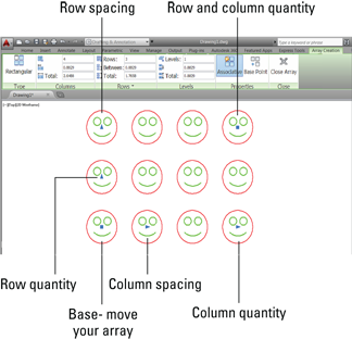
Figure 18-1: You’re ready to dynamically define your associative array.
5. Grip-edit your array.
As you play with the following options, observe how the dynamic preview constantly updates.
Each grip (see Figure 18-1) controls a different aspect of your array, as follows:
• Row 1, column 1: Base. You can move your array to a different location as you create it. After you select this grip, you can drag and drop it to a new location (object snaps work), or you can enter X and Y values at the dynamic cursor prompt.
• Row 1, column 2: Column spacing. Drag this grip (or enter a value at the dynamic prompt) to change the spacing of all columns.
You can enter a negative value, or you can drag to the left of row 1, column 1 to make your array grow in the opposite direction.
• Row 1, column 4: Column quantity. Drag this grip (or enter a value at the dynamic prompt) to change the quantity of columns.
• Column 1, row 2: Row spacing. Drag this grip (or enter a value at the dynamic prompt) to change the spacing of all rows.
You can enter a negative value, or you can drag below row 1, column 1 to make your array grow in the opposite direction.
• Column 1, row 3: Row quantity. Drag this grip (or enter a value at the dynamic prompt) to change the quantity of rows.
• Row 3, column 4: Row and column quantity. Drag this grip (or enter values at the dynamic prompt) to change the quantity of rows and columns at the same time.
6. Check out the other methods of specifying your array.
The AutoCAD 2013 changes to the Array feature gave you three basic methods for defining your array, one of which is grip-editing. The interesting option is that the command line continues to show almost all the prompts. Typically, command line input forces you to follow a specific sequence, but ARray in AutoCAD 2014 allows you to enter any command line option at any time.
Earlier, we mention that the Ribbon displays the Array Creation contextual tab while you’re defining your array. At any time, you can enter specific values for anything we have discussed so far, but it also has an extra functionality: The Columns and Rows panels each have a Total field, referring to a total distance. If you enter values in either window, the column and/or row spacing will be adjusted so that the number of rows and/or columns fit exactly within the specified distance.
7. Finish building your array.
If you don’t have a grip selected, the default mode is eXit. Simply press Enter or the spacebar, or click the Close Array button on the Ribbon, and you’re done!
The Rows panel of the Array Creation contextual tab of the Ribbon includes options for vertical (Z axis) values. If you’re working in 3D, you can easily create a set of bleacher seats, for example, where the higher-numbered rows are at a higher elevation so everyone gets a good view.
Creating polar arrays
AutoCAD also offers the ARRAYPOLAR command for creating polar (circular) arrays, such as the bolt holes in a pipe flange, horses on a carousel, or chambers in a revolver. As we indicate earlier, it may be hidden in the drop-down list under the Array button on the Modify tab of the Home panel of the Ribbon.
The basic principles of a polar array are the same as a rectangular one:
![]() Each polar array is a single, associative object.
Each polar array is a single, associative object.
![]() Objects within an array can be edited separately. We cover this a little later in this chapter.
Objects within an array can be edited separately. We cover this a little later in this chapter.
![]() As you create them, you see a dynamic preview of what the final array will look like.
As you create them, you see a dynamic preview of what the final array will look like.
![]() You can specify your input to the command through grip edits, the command line, the Dynamic Input, and/or the Polar version of the Array Creation tab of the Ribbon.
You can specify your input to the command through grip edits, the command line, the Dynamic Input, and/or the Polar version of the Array Creation tab of the Ribbon.
But polar arrays also have a few differences:
![]() When you finish selecting the objects to be arrayed, you are asked for a center point for the array. Note that normal object snaps can be most helpful here.
When you finish selecting the objects to be arrayed, you are asked for a center point for the array. Note that normal object snaps can be most helpful here.
![]() After you select the center point, a six-item dynamic preview with editing grips appears, along with the polar variant of the Array Creation tab of the Ribbon.
After you select the center point, a six-item dynamic preview with editing grips appears, along with the polar variant of the Array Creation tab of the Ribbon.
![]() Input specifications include
Input specifications include
• The radius of the array.
• The number of items in the array.
• The angle to fill.
A gear sector, for example, might need only ten teeth in a 60-degree segment.
• The number of rows.
Although this seems to be strange terminology for a circular pattern, you can specify the number of concentric repeats of the circular pattern and the radial distance between them, like the growth rings of a tree.
• Whether items are rotated (for example, gear teeth) or not (Ferris wheel seats) as the array is produced.
• The number of levels and the Z direction spacing between them.
Down the garden path
Associative arrays have a third type that isn’t available when you use ARRAYCLASSIC or -ARray to produce a simple array.
Unlike rectangular and polar arrays, which require only source objects and some input parameters, path arrays require an additional piece of drawing geometry — a path. A path can be as simple as a line or a circle, or it can be a spline or a 2D or 3D polyline. Other than that, path arrays behave very much like rectangular and polar arrays.
In the following steps, we show you how to use the ARRAYPATH command to bring chairs to an elliptical dining room table and use the table itself as the path.
1. Open a drawing containing some objects you want to array along a path (or draw some simple geometry for your source object) and then also draw a line or an open or a closed spline or polyline for your path.
![]() 2. Click Path Array from the Array drop-down button on the Modify panel of the Home tab.
2. Click Path Array from the Array drop-down button on the Modify panel of the Home tab.
AutoCAD prompts:
Select objects:
3. At the Select Objects prompt, select one or more objects that you want to array along a path.
You can select any and all AutoCAD object types, including block insertions and text.
Object arraying is done based on the position of the objects relative to the starting end of the path object. If you want the arrayed objects to land on the path, they must be on the path before you select them.
When you finish selecting objects, AutoCAD prompts:
Select path curve:
4. Select the object you want to serve as the path.
Valid object types include straight lines, open or closed polylines and splines, arcs, circles, and ellipses, as well as helixes and 3D polylines.
You don’t have to press Enter after you select the path. AutoCAD immediately responds with a lengthy, multi-option prompt, displays a dynamic preview, and displays the path version of the Array Creation contextual Ribbon tab.
5. Enter the specifications for your array.
As with rectangular and polar arrays, you can specify the number of items, the distance between them, and/or the length of a portion of the path to fill. A bit of experimentation will show that these options are often interrelated; changing one forces another one to change. You can also specify whether the arrayed objects stay horizontal or rotate to stay parallel to the path.
Again, just like the other array types, you can jump back and forth between grip-editing, Ribbon entries, the command line options, and Dynamic Input tooltip.
6. Finish building your array.
If you don’t have a grip selected, the default mode is eXit. Simply press Enter or the spacebar, or click the Close Array button on the Ribbon, and you’re done!
Put the path object on a separate layer. After you complete the array, freeze that layer, and the path object becomes invisible. We cover layers in Chapter 9.
Figure 18-2 shows the finished path array.

Figure 18-2: Down the garden path, using a path array.
Associatively editing
If you click any arrayed element (not the path of a path array), AutoCAD displays the Array contextual tab on the Ribbon. From here, you can revise pretty much every aspect of the array definition. In addition, the Options panel appears near the end of the Array tab.
![]() You need a special tool for tinkering with the entrails of associative arrays, and AutoCAD provides it with the ARRAYEDIT command. The three items on the Options panel link to the three options of this command. Start with a typical scenario: You just finished the drawing of the garden path when the client comes in and announces that the steppingstones need to be bigger.
You need a special tool for tinkering with the entrails of associative arrays, and AutoCAD provides it with the ARRAYEDIT command. The three items on the Options panel link to the three options of this command. Start with a typical scenario: You just finished the drawing of the garden path when the client comes in and announces that the steppingstones need to be bigger.
No problem. Select any one of the steppingstones (but not the spline path curve itself) in the array. Now click the Edit Source button in the Options panel of the Array tab, and then select any one of the arrayed items. Edit it to your heart’s content, including adding and moving objects, changing layers, and deleting objects. When you’re finished, select Save Changes from the Edit Array panel at the end of the current tab of the Ribbon, and all the arrayed items update.
So far, so good, but now the client wants a square steppingstone to replace one of the circular ones halfway down the path (see Figure 18-3). No problem. Step through the following steps (pun intended):
1. Draw the new steppingstone.
The easiest way to do this is to use the RECtang command, as we discuss in Chapter 6.
2. Select the array you want to edit.
Select any object in the path array.
Don’t select the path itself, or you’ll be editing the path, not the array.
3. Click Replace Item on the Options panel of the Array contextual tab.
4. Select the replacement stone. Press Enter to continue.
5. Select the base point of the replacement rectangular stone.
Select a point about in the center of the rectangle. This is the point that will end up sitting exactly on the path.
6. Select one or more existing circular stones to replace in the array. Press Enter to continue.
The objects you select in the array are replaced with the new object.
7. Press Enter or select eXit from the context menu.

Figure 18-3: Going down a different path: The results of editing an associative array.
Oops! You replaced the wrong steppingstone. No problem. Select the array, and then select Reset Array from the Options panel of the Array tab. Voilà! Your changes are undone. Now you can replace it with the correct one.
Earlier, we emphasize the importance of selecting an arrayed item in a path array and not the path. The reason for this is simple: The path can be edited separately. Simply select it and then edit it like the object that it is. When you’re finished, the path array updates to match the revised path.
And no matter how much tinkering you do, you can always revert to the original state by clicking Reset Array on the Options panel of the Array tab.
Going External
In AutoCAD, an xref (external reference) is a reference to an external drawing file — one outside the current drawing — that acts as though it’s part of your drawing. It’s a way to see two drawings at the same time, superimposed. Technically, a reference is a simple pointer from one file to another. The xref is the actual pointer, but many people call the combination of the pointer and the external file “the xref.” By the way, xref is pronounced exactly as it’s spelled. Just fooling; it’s pronounced “ex ref.”
In both AutoCAD and AutoCAD LT, external drawing files are just one of several file types you can attach to your current drawing via the Select Reference File dialog box. You use this dialog box to attach externally referenced AutoCAD drawings (xrefs), raster image files, DWF and DWFx files, PDF files, and MicroStation DGN drawing files, among others.
![]() Click the Attach button of the Insert tab’s Reference panel to open the Select Reference File dialog box. When you attach an external drawing to your current drawing, you become the host of the external file. No need to break out the cocktails and canapés, though, because it’s actually your current drawing that’s doing the hosting — and in AutoCAD, it’s called (what else?) the host drawing. You can think of the attached xrefs as guests, but most of the time they’re pretty well behaved ones — and like the best of guests, they go away as soon as you want them to.
Click the Attach button of the Insert tab’s Reference panel to open the Select Reference File dialog box. When you attach an external drawing to your current drawing, you become the host of the external file. No need to break out the cocktails and canapés, though, because it’s actually your current drawing that’s doing the hosting — and in AutoCAD, it’s called (what else?) the host drawing. You can think of the attached xrefs as guests, but most of the time they’re pretty well behaved ones — and like the best of guests, they go away as soon as you want them to.
Xrefs have a big advantage over blocks: If a drawing is inserted as a block into another drawing, its geometry doesn’t change if the original drawing is changed in any way. It always looks the way it looks when it’s inserted. If that drawing is attached as an xref, however, AutoCAD will automatically update every host drawing to which it’s attached when the host drawing is reopened. You can also manually reload the changed xref if you don’t want to close and reopen the host drawing.
When you open a drawing that contains xrefs, AutoCAD displays a little symbol (looks like papers with a binder clip) on the right end of the status bar. This symbol alerts you that some of the things you see in the drawing are actually parts of other, xref-ed drawings. If an xref changes while you have the host drawing open (because you or someone else opens and saves the referenced drawing), the status bar xref symbol displays an External Reference Files Have Changed balloon notification. Simply click the Reload link in the balloon notification to show the updated xrefs. (If you want to change how AutoCAD checks for changes, look up XREFNOTIFY in the online help.)
Another advantage that xrefs have over blocks is that their contents aren’t stored in your drawing even once. The disk storage space taken up by the original drawing (the xref) isn’t duplicated, no matter how many host drawings reference it. This characteristic makes xrefs much more efficient than blocks for larger drawings that are reused several times.
Sure, you can always buy a larger hard drive, so the storage issue isn’t crucial. The key benefit of xrefs is that they enable you to organize your drawings so the changes you make to a single drawing file automatically ripple through all the host drawings into which it’s xref-ed. This benefit is even greater on larger projects involving multiple drafters, each of whose work may be incorporated in part or in whole in the work of others.
You can use xrefs to your advantage in almost any type of drawing. For example, several drafters might be working on the components for a large machine, while one master drawing brings them all together in the final assembly. Similarly, a set of separate architectural drawings could show electrical, plumbing, HVAC, and so on with everyone referencing the same floor plan. The host file would contain nothing but a title block and xrefs to the other files.
As a bare minimum, the border and title block of almost every drawing should be an xref. This saves a tremendous amount of disk space in the long run, plus should corporate ownership (and hence the corporate logo) change yet again, you just need to revise the xref master files instead of every drawing individually.
The automatic update feature of xrefs is a big advantage only if you’re organized about how you use xrefs. Suppose that an architect creates a plan drawing showing a building’s walls and other major features that are common to the architectural, structural, plumbing, and electrical plan drawings. The architect then tells the structural, plumbing, and electrical drafters to xref this background plan into their drawings so that everyone is working from a consistent and reusable set of common plan elements. If the architect decides to revise the wall locations and updates the xref-ed drawing, everyone will see the new wall configuration and be able to change their drawings. But if the architect absent-mindedly adds architecture-specific objects (toilets and furniture, for example) to the xref-ed drawing or shifts all the objects with respect to 0,0, everyone else will unnecessarily see the furniture or all the walls shifted over. If people in your office share xrefs, create a protocol for who is allowed to modify which file when and what communication needs to take place after a shared xref is modified.
Becoming attached to your xrefs
Attaching an external reference drawing is similar to inserting a block, and almost as easy. Just use the following steps:
1. Set an appropriate layer current, as described in Chapter 9.
Insert xrefs on a separate layer from all other objects.
Note that if you freeze the layer on which an xref is inserted, the entire xref disappears. (This behavior can be a handy tip, a nasty surprise, or a fun trick.)
2. If the External References palette isn’t already open, click its icon (it looks like a sheaf of papers with a bulldog clip and a silhouetted user) on the Palettes panel of the View tab to open it.
Use the toolbar at the top of the palette to attach an external DWG file, a DWF underlay, a PDF underlay, a MicroStation DGN drawing file, a raster image file, or a point cloud. We cover attaching images and DWFs or PDFs later in this chapter. If you need to attach DGN files, visit the online help.
3. Click Attach DWG. Click the down arrow if the tooltip offers to attach something else; see Figure 18-4.
The Select Reference File dialog box appears.
4. Browse to find the file you want to attach, select it, and then click Open.
The Attach External Reference dialog box appears.
5. Specify the parameters for the xref in the dialog box.
Parameters include the insertion point, scaling factors, location based on geographic data, and rotation angle. (We describe geographic location briefly in Chapter 17.) You can set these parameters in the dialog box or specify them onscreen, just like you can do when inserting a block, as described in Chapter 17.
The Path Type drop-down list provides more flexibility in how the xref path is stored. See the “Forging an xref path” section, later in this chapter, for more information.
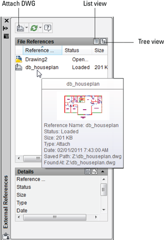
Figure 18-4: Use the External References palette to attach an xref.
We recommend that you choose Relative Path instead of Full Path. This makes it easier to move a full set of drawings to another location if all the xrefs are located below the host.
6. Click OK.
The externally referenced file appears in your drawing.
In drawings that contain many xrefs, locating the one you want can be difficult. When you select an object that’s part of an xref in the drawing area, the xref name is highlighted in the External References palette. Likewise, selecting an xref in the External References palette highlights the attached file geometry in the drawing editor.
You can select either the Attachment or Overlay option to tell AutoCAD how to handle the xref. The choice matters only if you create a drawing that uses xrefs, and then your drawing is, in turn, used as an xref. Attachment is the default choice, and it dictates that the xref-ed file will always be included with your drawing when someone else uses your drawing as an xref. Overlay, the other choice, means that you see the xref-ed drawing, but someone who xrefs your drawing won’t see the overlaid file. By choosing Overlay, you can xref a map, for example, to your drawing of a house, but the map won’t show up when someone else xrefs your house drawing. (That person can xref the map, if needed.) We recommend that you use the default Attachment reference type unless you have a specific reason not to.
One use of Overlay mode is to avoid circular references. If drawing A references drawing B, which references drawing C, and then C references A, you have an infinite loop. If C references A as an overlay, though, C doesn’t see B, and so the loop is broken.
 AutoCAD 2014 allows you to switch the attachment type for an xref between Attach and Overlay by double-clicking in the Type column. Better yet, a new right-click menu option lets you change the xref type for several selected xrefs all at once.
Layer-palooza
When you attach or overlay an xref, AutoCAD adds new layers to your current drawing that correspond to the layers in the xref-ed DWG file. The new layers are assigned names that combine the drawing name and layer name. For example, if you xref the drawing MYSCREW.DWG (which has the layer names GEOMETRY, TEXT, and so on), the xref-ed layers will be named MYSCREW|GEOMETRY, MYSCREW|TEXT, and so on. By creating separate layers corresponding to each layer in the xref-ed file, AutoCAD eliminates the potential problem with blocks that we warn you about in Chapter 17, when layers have the same name but different color or linetype in the two drawings.
A host drawing with many xrefs can end up with some pretty cluttered dialog boxes and palettes. Starting with AutoCAD 2014, xref linetypes are not displayed in the linetype list of the Properties palette or of the Ribbon, but the Ribbon still displays xref layers, so you can control their visibility.
Creating and editing an external reference file
To create a file that you can use as an external reference, just create a drawing and save it. That’s it. You can then create or open another drawing and create an external reference to the previous one. The xref-ed drawing appears in the host drawing as a single object, very much like a block insertion. In other words, if you click any object in the xref, AutoCAD selects the entire xref. You can measure or object snap to the xref-ed geometry, but you can’t modify or delete individual objects in the xref. You need to open the xref drawing itself to edit its geometry.
The XOPEN command provides a quick way to open an xref-ed drawing for editing. You just start the command and pick any object in the xref. Alternatively, you can select the xref from the External References palette and then right-click and choose Open to open one or more xrefs for editing. See the “Managing xrefs” section, later in this chapter, for more information.
![]() An alternative to opening the xref-ed file when you need to edit it is to use the REFEDIT command. Use REFEDIT (short for Reference Edit) to edit the external file from within the host drawing, rather than having to open the reference in its own window. Look up REFEDIT in the AutoCAD online help system’s Command Reference.
An alternative to opening the xref-ed file when you need to edit it is to use the REFEDIT command. Use REFEDIT (short for Reference Edit) to edit the external file from within the host drawing, rather than having to open the reference in its own window. Look up REFEDIT in the AutoCAD online help system’s Command Reference.
With several xrefs attached to your drawing, or with a very complex xref, it can be difficult to tell which objects belong to the drawing you’re editing and which are part of the xref. You can fade your xrefs so you can tell them apart from your drawing’s objects as follows:
1. Open a drawing containing an external reference drawing.
Alternatively, you can attach a drawing to your current drawing by following the steps in the “Becoming attached to your xrefs” section, earlier in this chapter.
2. On the Insert tab, click the Reference panel label to open the Reference slideout.
The Reference slideout also contains the Edit Reference button, which runs the REFEDIT command.
![]() 3. Click the Xref Fading button to toggle reference fading off and on.
3. Click the Xref Fading button to toggle reference fading off and on.
4. Drag the Xref Fading slider to increase or decrease the level of fading in the reference file.
The default value is 70; increasing the value toward 90 (the maximum) increases the degree of fading, and lowering it reduces the fade level.
Forging an xref path
When you attach an xref, one option is to have the host drawing store the xref’s full path — that is, the drive letter and sequence of folders and subfolders all the way down to the folder in which the DWG file resides — along with the filename. This behavior corresponds to the Full Path setting in the Path Type drop-down list. Figure 18-5 shows the three xref path options. Full Path works fine as long as you never move files on your hard drive or network and never send your DWG files to anyone else — which is to say, it almost never works fine!

Figure 18-5: Follow the path less traveled when you attach an xref.
At the other end of the path spectrum, the No Path option causes AutoCAD to not store any path with the xref attachment: Only the filename is stored. This is the easiest and best option if the host drawings and the xrefs reside in the same folder. However, if the host and the xref are in different folders, you have to browse to find the reference file every time you open the host drawing.
If you prefer to organize the DWG files for a particular project in more than one folder, you’ll appreciate AutoCAD’s Relative Path option, as shown in Figure 18-5. This option permits xref-ing across more complex folder structures but avoids many of the problems that the Full Path option can cause. For example, you may have a host drawing
H:Project-XPlansFirst floor.dwg
that xrefs
H:Project-XCommonColumn grid.dwg
If you choose Relative Path, AutoCAD will store the xref path as
..CommonColumn grid.dwg
instead of
H:Project-XCommonColumn grid.dwg
This way, if you decide to move the Project-X folder and its subfolders to a different drive (or send them to someone else who doesn't have an H: drive), AutoCAD can still find the xrefs.
When attaching an external reference, we strongly recommend you check the Path Type section and make sure it says Relative Path. If not, select Relative Path from the drop-down list from this section.
When you use Relative Path, you’ll see xref paths that include these special codes:
![]() Single period (
Single period (.): This indicates this host drawing's folder.
![]() Double period (
Double period (..): This indicates the folder above this host drawing's folder.
You can report on and change xref paths for a set of drawings with the Reference Manager (not in AutoCAD LT). See Chapter 20 for more information.
If all these path options and periods leave you feeling punchy, you can keep your life simple by always keeping host and xref drawings in the same folder and using the No Path option when you attach xrefs. On the other hand, it can get a little messy when a file such as a standard title block and border is xref-ed into many different drawings for several different projects and you want to keep each project’s files in separate folders. The best solution is usually a bit of each; the title block and border can have a specific path in each host, but the other project files don’t.
Managing xrefs
The External References palette includes many more options for managing xrefs after you attach them. Many of these options are hiding in right-click menus. Important options include
![]() List of external references: You can change between the List view and Tree view of your drawing’s external references by clicking the appropriate button at the top of the palette (refer to Figure 18-4). You can resize the columns by dragging the column dividers or re-sort the list by clicking the column header names, just like in Windows or File Explorer.
List of external references: You can change between the List view and Tree view of your drawing’s external references by clicking the appropriate button at the top of the palette (refer to Figure 18-4). You can resize the columns by dragging the column dividers or re-sort the list by clicking the column header names, just like in Windows or File Explorer.
![]() Unload: Right-click an xref and choose Unload to make the selected xref disappear from the onscreen display of your drawing and from any plots you do of it but yet retain the pointer and attachment information. Right-click again and choose Reload to redisplay an unloaded xref.
Unload: Right-click an xref and choose Unload to make the selected xref disappear from the onscreen display of your drawing and from any plots you do of it but yet retain the pointer and attachment information. Right-click again and choose Reload to redisplay an unloaded xref.
![]() Reload: Right-click an xref and choose Reload to force AutoCAD to reread the selected xref-ed DWG file from the disk and update your drawing with its latest contents. This feature is handy when you share xrefs on a network, and someone has just made changes to a drawing that you’ve xref-ed.
Reload: Right-click an xref and choose Reload to force AutoCAD to reread the selected xref-ed DWG file from the disk and update your drawing with its latest contents. This feature is handy when you share xrefs on a network, and someone has just made changes to a drawing that you’ve xref-ed.
![]() Detach: Right-click an xref in the External References palette and choose Detach to completely remove the selected reference to the external file from your drawing.
Detach: Right-click an xref in the External References palette and choose Detach to completely remove the selected reference to the external file from your drawing.
![]() Bind: Right-click an xref and choose Bind to bring the selected xref into your drawing and turn it into a block definition. You might, for example, use this function to roll up a complex set of xrefs into a single archive drawing.
Bind: Right-click an xref and choose Bind to bring the selected xref into your drawing and turn it into a block definition. You might, for example, use this function to roll up a complex set of xrefs into a single archive drawing.
In many offices, binding xrefs without an acceptable reason for doing so is a crime as heinous as exploding blocks indiscriminately. In both cases, you’re eliminating an important data management link. Find out what the policies are in your company. When in doubt, keep yourself out of a bind. And even when you do have a good reason to bind, you generally should do it on a copy of the host drawing.
![]() Path: Right-click an xref in the External References palette and choose Path to bring up a submenu to switch to no path (Remove), Relative, or Absolute.
Path: Right-click an xref in the External References palette and choose Path to bring up a submenu to switch to no path (Remove), Relative, or Absolute.
![]() Open: Right-click an xref and choose Open to open one or more xref drawings in separate drawing windows. After you edit and save an xref drawing, return to the host drawing and use the Reload option in the External References palette to show the changes.
Open: Right-click an xref and choose Open to open one or more xref drawings in separate drawing windows. After you edit and save an xref drawing, return to the host drawing and use the Reload option in the External References palette to show the changes.
None of these options (other than opening and editing the xref) affects the xref-ed drawing itself; it continues to exist as a separate DWG file. If you need to delete or move the DWG file that the xref refers to, do it in Windows or File Explorer.
The fact that the xref-ed drawing is a separate file is a potential source of problems when you send your drawing to someone else; that someone else needs all the files that your drawing depends on, or it will be useless. Make sure to include xref-ed files in the package with your drawing. See Chapter 20 to find out how.
Both AutoCAD and AutoCAD LT include an additional xref feature called xref clipping. You can clip any kind of externally referenced file or block insertion so that only part of it appears in the host drawing. Use the CLIP command to trim away unwanted parts of xref drawings, DWF and DWFx files, raster images, MicroStation DGN files, or PDFs. You can even use CLIP on block insertions. For more information, look up CLIP in the online help’s Command Reference section.
Blocks, Xrefs, and Drawing Organization
Blocks and xrefs are useful for organizing sets of drawings to use and update repeated elements. When to use blocks and when to use xrefs isn’t always clear, though. Applications for xrefs include
![]() The parts of a title block that are the same on all sheets in a project
The parts of a title block that are the same on all sheets in a project
![]() Reference elements that must appear in multiple drawings (for example, wall outlines, site topography, and column grids)
Reference elements that must appear in multiple drawings (for example, wall outlines, site topography, and column grids)
![]() Assemblies that are repeated in one or more drawings, especially if the assemblies are likely to change together (for example, a motor, coupling, speed reducer, and base plate assembly in large machines)
Assemblies that are repeated in one or more drawings, especially if the assemblies are likely to change together (for example, a motor, coupling, speed reducer, and base plate assembly in large machines)
![]() Pasting up several drawings (for example, details or a couple of plans) onto one plot sheet
Pasting up several drawings (for example, details or a couple of plans) onto one plot sheet
![]() Temporarily attaching a background drawing for reference or tracing
Temporarily attaching a background drawing for reference or tracing
On the other hand, blocks remain useful in simpler circumstances. Situations in which you might stick with a block are
![]() Components that aren’t likely to change
Components that aren’t likely to change
![]() Simple components
Simple components
![]() An assembly that’s used repeatedly but in only one drawing
An assembly that’s used repeatedly but in only one drawing
![]() When you want to include attributes (variable text fields) that you can fill in each time you insert a block
When you want to include attributes (variable text fields) that you can fill in each time you insert a block
Blocks let you include attribute definitions; xrefs don’t. Refer to Chapter 17 for the lowdown on attributes.
Everyone in a company or workgroup should aim for consistency as to when and how they use blocks and xrefs. Check whether guidelines exist for using blocks and xrefs in your office. If so, follow them; if not, it would be a good idea to develop some guidelines.
Mastering the Raster
AutoCAD includes four more xref-like features: the ability to attach raster images, DWF files, PDF files, and DGN files to drawings. We cover DWF and PDF files in the next section and refer you to the online help if you should find some DGN files on your hands. The image feature is useful for adding a raster logo to a drawing title block or placing a photographed map or scene behind a drawing. A raster, or bitmapped, image is one that’s stored as a field of tiny dots.
Raster images often come from digital cameras or from other programs, such as Photoshop. Raster images can also come into the computer from some kind of scanner that imports a blueline print, photograph, or other image.
AutoCAD drawings are vector files. A vector drawing is a graphic file defined by storing geometrical definitions of a bunch of objects. Typical objects include a line (defined by its two endpoints) and a circle (defined by its center point and radius). Vector-based images are typically smaller (in terms of the disk space they occupy) and more flexible than raster images but also are less capable of displaying visually rich images, such as photographs.
Whether you’re doing your own scanning or having a service bureau do it for you, you need to know that AutoCAD handles most popular image file formats, including the Windows BMP format; the popular web graphics formats GIF, JPEG, and PNG; common print formats, such as PCX and TIFF; the less popular DIB, FLC, FLI, GP4, MIL, RLE, RST, TGA formats, and several even more obscure ones.
Three scenarios in which you could incorporate raster images in your drawing include
![]() Small stuff: You can add logos, special symbols, and other small images that you have in raster files.
Small stuff: You can add logos, special symbols, and other small images that you have in raster files.
![]() Photographs and maps: You can add photographs (such as a future building site) and maps (for example, showing the project location).
Photographs and maps: You can add photographs (such as a future building site) and maps (for example, showing the project location).
![]() Vectorization: To convert a raster image into a vector drawing by tracing lines in the raster image, you can attach the raster image in your drawing, trace the needed lines by using AutoCAD commands, and then detach the raster image. (This procedure is okay for a simple raster image; add-on software is available, from Autodesk and others, to support automatic or semiautomatic vectorization of more-complex images.)
Vectorization: To convert a raster image into a vector drawing by tracing lines in the raster image, you can attach the raster image in your drawing, trace the needed lines by using AutoCAD commands, and then detach the raster image. (This procedure is okay for a simple raster image; add-on software is available, from Autodesk and others, to support automatic or semiautomatic vectorization of more-complex images.)
Your raster image may be distorted a bit; for example, the aspect ratio (ratio of width to height) may not be correct, but AutoCAD won’t let you change it. No problem; simply attach the raster image, make a block that contains it, and then insert the block with different X and Y scale factors. We love cheating.
Using raster images is much like using external references. The raster image isn’t stored with your drawing file, though. Instead, a reference to the raster image file is established from within your drawing, like an xref. You can clip the image and control its size, brightness, contrast, fade, and transparency. These controls fine-tune the appearance of the raster image onscreen and on a plot.
When you attach raster images, you have to make sure that you send the raster files along when you send your drawing to someone else. Raster images are simply referenced from the drawing and aren’t part of it. If you don’t send the raster image file along with the drawing, the drawing displays a rectangle containing the name of the missing file in its place. The best way to make sure that you get all the required files when sending a drawing file to someone else is to use the ETRANSMIT command, which we cover in Chapter 20.
Some raster image files that you find on the Internet may not be appropriate as AutoCAD attachments.
Attaching a raster image
Follow these steps to bring a raster image into AutoCAD:
1. If the External References palette isn’t already open, click its icon on the Palettes panel of the View tab.
Use the drop-down list on the first toolbar button to attach a drawing; an image; or a DWF, PDF, or DGN file.
2. Click Attach Image and locate the image file you want to attach.
The Attach Image dialog box appears, as shown in Figure 18-6.
3. Browse to find the file you want to attach, select it, and then click Open.
The Attach Image dialog box appears.
Click the Show Details button in the Attach Image dialog box to see more information about the resolution and image size of the image you’re attaching.
4. Specify the parameters for the attached image in the dialog box.
Parameters include the insertion point, scale factor, and rotation angle. You can set these parameters in the dialog box or specify them onscreen, similar to what you can do with blocks and external references, as described earlier in this chapter.

Figure 18-6: The Attach Image dialog box.
The Attach Image dialog box includes the same Full Path, Relative Path, and No Path options as those for attaching xrefs. (See the “Forging an xref path” section, earlier in this chapter.)
5. Click OK.
The image appears in your drawing.
6. If you need to ensure that the raster image floats behind other objects in the drawing, select the raster image, right-click, choose Draw Order, and then choose Send to Back.
The DRaworder command provides additional options for which objects appear on top of which other objects. If you need this kind of flexibility, look up DRaworder command in the AutoCAD online help system.
Maintaining your image
You manage the images in your drawing via the External References palette. You can view a list of image files that appear in the current drawing, detach (remove) image references, and unload and reload images when needed. You can’t bind an image to your drawing, though; it always remains an external file.
You can clip images so that only part of the image is displayed in your drawing. Choose Clip from the Insert tab’s Reference panel and follow the prompts to clip the image. You can have multiple overlapping or distinct pieces of any number of images in your drawing, and only the parts you need are loaded into memory when you have your drawing open.
Raster image files often are larger than DWG files of corresponding complexity; raster file size can affect performance within AutoCAD because the entire raster file loads into memory when you’re working on your drawing. If you find raster attachments slowing down AutoCAD’s response, then follow these tips:
![]() Attach raster images late in the production process.
Attach raster images late in the production process.
![]() Create a lower-resolution version of the raster file, just large enough to create the desired effect in your drawing.
Create a lower-resolution version of the raster file, just large enough to create the desired effect in your drawing.
![]() Right-click an image in the External References palette and choose Unload from the context menu to temporarily hide an image without losing the attachment information.
Right-click an image in the External References palette and choose Unload from the context menu to temporarily hide an image without losing the attachment information.
In addition, raster files can also dramatically increase the time that AutoCAD takes to generate plots (and the plot file sizes). Before you settle on using large raster files in your AutoCAD drawing, do some testing on zooming, editing, and plotting.
Starting in AutoCAD 2014, you can insert a link to a mapping service, such as Google Earth, to act as an underlay in your drawing.
You Say PDF, We Say DWF
The Adobe PDF format has been around for a very long time, and for a while, it seemed like Autodesk was trying to supplant it with its own universal file format: DWF (Design Web Format). That didn’t happen, but if you can’t beat ’em. . . . AutoCAD includes a very acceptable PDF printer driver, and both PDF and DWF are suitable candidates for external reference attachments.
You could think of a DWF as “DWG Lite” because it looks just like a drawing file and contains some of the actual drawing file data. We talk more about the web side of DWFs in Chapter 20; in this section, we explain how you can use DWFs as well as PDFs as reference files in your own drawings. (Some people call DWF files “dwiffs,” but we’re going to hold off on that one until we start hearing DWG files called “dwiggs.” And why is phonetic spelled that way?)
You create both DWFs and PDFs from within AutoCAD in one of two ways. Either choose Plot and then select a DWF or PDF option in the Printer/Plotter name list, or choose Print⇒Batch Plot from the Application Menu and then choose DWF, DWFx, or PDF from the Publish To area of the Publish dialog box.
Both file types are compact and secure. Because you can’t edit either PDFs or DWFs in AutoCAD, both formats are ideal for two purposes:
![]() You can post DWFs or PDFs on the web.
You can post DWFs or PDFs on the web.
![]() You can send your drawings to consultants and clients in a form that they can’t mess up.
You can send your drawings to consultants and clients in a form that they can’t mess up.
You can attach PDFs or DWFs to your drawing files in pretty much the same way you attach drawings as external references. DWFs and PDFs attached to drawing files are referred to as DWF underlays or PDF underlays.
As with DWF and DGN attachments, you can object-snap to entities in the PDF underlay by enabling the Snap to Underlays function in the Reference panel slideout on the Insert tab. Setting PDF parameters is virtually identical to setting DWF parameters, and you can attach a PDF to your drawing by using exactly the same steps as the ones that follow.
The previous sections show how to attach a DWG and a raster image. Follow these steps to attach a DWF (or a PDF!) file as an underlay:
1. If the External References palette isn’t already open, click its icon on the Palettes panel of the View tab to open it.
Use the toolbar at the top of the palette to attach an external file as an xref, a raster image file, or a DGN or DWF underlay. We cover attaching xrefs and images earlier in this chapter. See the online help for information on attaching DGN files.
2. Click Attach DWF or Attach PDF and then locate the file you want to attach.
The Select Reference File dialog box appears.
3. Browse to find the file you want to attach, select it, and then click Open.
The Attach DWF Underlay or the Attach PDF Underlay dialog box appears.
4. Specify the parameters for the DWF or the PDF in the dialog box.
Parameters include specifying a sheet, the insertion point, scaling factors, rotation angle, and path type (see Figure 18-7). You can set these parameters in the dialog box or specify them onscreen, just like you can do when inserting a block, attaching an xref, or attaching an image, as described earlier in this chapter.
5. Click OK.
The externally referenced DWF or PDF file appears in your drawing.
Neither PDF nor DWF files are as precise as DWGs, and that's why their file size is a lot smaller. When using object snaps to locate points in DWFs, you may see the word approximate on the Object Snap tooltip. If this is a problem, you can increase the precision of your DWF file when you create it.
AutoCAD allows you to import about 20 different file formats into an AutoCAD drawing. Most of these are 3D modeling formats. They are imported into model space (not attached or xref-ed), and are used as the basis for additional 3D modeling and editing and/or for generating 2D working drawings from them. We discuss 3D to 2D in Chapter 23.

Figure 18-7: The Attach PDF Underlay dialog box.
Theme and Variations: Dynamic Blocks
You can add variety to your blocks by making them dynamic. The two most useful applications for dynamic blocks are multiple presentations of similar objects and manipulation of components within individual block inserts.
AutoCAD dynamic blocks feature offers you a great deal of flexibility to block creation and insertion, but using them is also a very complicated system with its own set of commands and system variables. We recommend that you become very familiar with regular block creation and insertion techniques for creating and inserting blocks (which we describe in Chapter 17) before you tackle dynamic blocks.
Spend some time planning your dynamic blocks. Sketch out the geometry for each variation in appearance (visibility state) and decide where the common base point should be. Unless you’re a lot smarter than we are, you’ll probably find that creating dynamic blocks is complex enough without trying to design your blocks as you go.
Now you see it
If your drawing shows six different kinds of seats, one approach is to create three different standard blocks to represent them all. Alternatively, you can create a single dynamic block and define visibility states to cover all three different types. The following steps show you how to make your blocks do double (or triple?) duty by using the Edit Block Definition dialog box:
1. Open a drawing that contains some block definitions you’d like to combine, or draw some simple geometry to make some similar types of objects.
You can find the files we use in this sequence of steps at this book's companion website. Go to www.dummies.com/go/autocad2014fd and download afd18.zip. The drawing named afd18b.dwg contains the three-piece furniture suite (see Figure 18-8) we use to create a dynamic block.
You can create dynamic blocks from scratch, or you can work with existing standard (nondynamic) block definitions. Figure 18-8 shows a drawing with three nondynamic blocks.
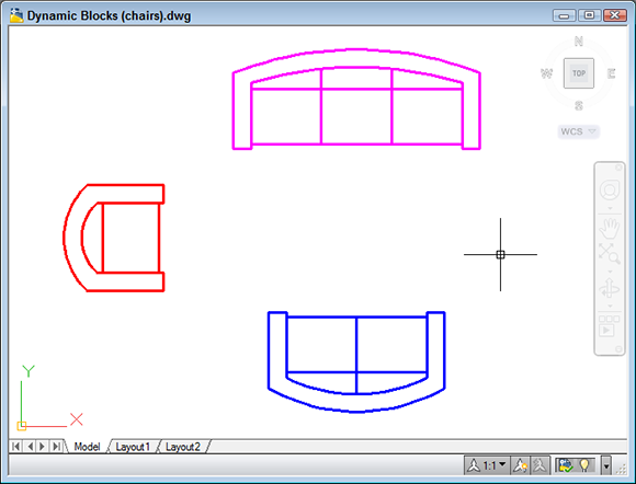
Figure 18-8: Three blocks to make three seats.
![]() 2. On the Block panel of the Home tab, choose Block Editor to open the Edit Block Definition dialog box.
2. On the Block panel of the Home tab, choose Block Editor to open the Edit Block Definition dialog box.
3. In the Block to Create or Edit box, specify a new block name or select Current Drawing; then click OK to display the Block Editor window.
The Block Editor is a special authoring environment with its own Ribbon tab plus a passel of command-line commands. You also have access to the rest of the Ribbon tabs, so you can draw and edit just like you would in the regular drawing window. The background color is different from the drawing editor’s background color to help you remember where you are.
 The Block Editor tab’s Geometric, Dimensional, and Manage panels (see Figure 18-9) are elements of the AutoCAD parametric drawing feature. (AutoCAD LT doesn’t fully support parametric drawing, so the LT Block Editor lacks the Geometric and Dimensional panels and gets a miniversion of the Manage panel.) In this book, we don’t have room to cover parametric constraints in dynamic blocks, but we do cover parametric drafting in Chapter 19. The concepts are pretty similar to adding parametric features to dynamic blocks.
If you enter a new block name, AutoCAD displays an empty block-authoring environment where you draw geometry or insert existing blocks. If you instead select Current Drawing, AutoCAD places all drawing objects inside the block-authoring environment.
4. Create some geometry for the first visibility state. Alternatively, click the Home tab, choose Insert on the Block panel, and select an existing block definition to serve as the first visibility state.
When creating geometry from scratch, pay attention to where the common base point should be. Although you use different blocks to assemble a multiple-view block, they should all have the same base point. (0,0 or the exact center are good ones for blocks.) You don’t want your chairs jumping around between different insertion points!
5. If you inserted an existing block in Step 4, deselect all three Specify On-Screen check boxes, make sure that the Explode check box is not selected, and then click OK.
6. Repeat Steps 4 and 5, drawing or inserting all the necessary geometry.
At this point, your drawing screen may look pretty strange (see Figure 18-9). Don’t worry; you’re going to fix it in the next steps.

Figure 18-9: Three seats in the Block Editor.
7. Click the Parameters tab of the Block Authoring Palettes and then click Visibility, as shown in Figure 18-9.
If the palettes aren’t open, click Authoring Palettes on the Manage panel on the highlighted Block Editor contextual tab of the Ribbon.
AutoCAD prompts you to specify the parameter location.
8. Click to place the parameter marker somewhere other than the base point location you chose in Step 4.
AutoCAD places a parameter marker at the selected point and returns to the command line. As shown in Figure 18-9, the label Visibility1 appears next to the Visibility Parameter marker, and a yellow Alert symbol indicates that no action has been assigned to the parameter yet. The controls on the Ribbon's Visibility panel become active.
The parameter location that you specify will be the spot on the block where the dynamic block option grip will be displayed. It’s not crucial where you locate this point, but try to pick a sensible location on the object. If you specify the same point for the parameter location as the base point for the block, you may have a hard time selecting the dynamic option grip.
9. Click Visibility States on the Visibility panel. Click Rename and change VisibilityState0 to something more descriptive. Then click OK.
As is the case with other named objects in AutoCAD, best practice is to assign useful, descriptive names rather than accept the default generic labels.
10. On the Visibility panel, click the Make Invisible button. At the Select Objects prompt, select the geometry or block inserts that should be invisible in the current visibility state — that is, those that are not associated with the current visibility state — and then press Enter.
AutoCAD prompts:
Hide for current state or all visibility states [Current/All] <Current>: C
11. Click Visibility States again and then click New to create a new visibility state.
12. In the New Visibility State dialog box, enter a descriptive name. Also select the Show All Existing Objects in New State option and then click OK.
All your geometry should reappear.
13. Repeat Steps 9 and 10 to create additional visibility states associated with the remaining geometry or blocks.
The geometry or block insert associated with the last created visibility state should be visible onscreen.
14. Click OK to close the Visibility States dialog box and then click Close Block Editor on the Ribbon. Save the changes to your new block or to Current Drawing.
AutoCAD displays an alert box asking whether you want to save changes to your block. Your choices are
• Cancel: Click Cancel to return to the Block Editor without saving your changes.
• Discard changes: Clicking Discard the Changes closes the Block Editor without saving your changes.
• Save: Click Save the Changes to update the block and exit.
AutoCAD closes the block-authoring environment and returns to the standard drawing editor window.
The Block Editor tab includes a Test Block tool you can use to see what your finished product will look like without the hassle of closing the editor and inserting or manipulating the block inside the drawing editor. Test Block displays the geometry and lets you try different parameters; then you can easily return to the Block Editor to tweak your masterpiece. You’ll find the Test Block button on the Open/Save panel of the Block Editor contextual tab.
Lights! Parameters!! Actions!!!
You can modify the appearance of individual instances of the same block by defining parameters and actions to move, rotate, flip, or align parts of them. You can adjust the block’s appearance while you insert it or at any time afterward. The following steps show you how to use the Block Editor to add some action to a block definition:
1. Open a drawing that contains some block definitions whose appearance you’d like to spice up a little, or draw some simple geometry that might make a suitably dynamic block.
Action parameters are most effective in block definitions that contain groups of related objects: for example, an office desk and chair or a furniture arrangement.
2. On the Block panel of the Ribbon’s Home tab, choose Block Editor to open the Edit Block Definition dialog box.
3. In the Block to Create or Edit text box, type a new block name or select Current Drawing. Then click OK.
4. Create some geometry or insert some blocks.
When you insert blocks, make sure that the Explode check box at the lower-left corner of the Insert dialog box is not selected. Then click OK.
Draw the geometry or insert the blocks in a group so that you can insert the finished arrangement into your drawings. For example, the upcoming Figure 18-10 shows the creation of a dynamic block for one cell of a telephone boiler-room call center.
5. Repeat Step 4 until you’ve drawn all the needed geometry or inserted all the necessary blocks.
6. Click the Parameters tab of the Block Authoring Palettes and then click Rotation Parameter.
AutoCAD prompts you to specify the parameter location.
7. Click to place the parameter marker somewhere on the object geometry other than the base-point location.
If you specify the same point for the parameter location as the base point for the block, you may have a hard time selecting the dynamic option grip.
8. AutoCAD places a parameter marker at the selected point and returns to the command line, prompting you to specify the radius of the rotation parameter and the default rotation angle.
The parameter marker’s label appears next to the rotation parameter marker.
9. Click the Actions tab of the Block Authoring Palettes and then click Rotate. Select Rotate Parameter, select the objects that should be modified when the grip is used, and specify a point for the action’s label.
AutoCAD returns to the command line. At this point, it’s fine to go with default values and onscreen pick points.
10. Repeat Steps 6–9, trying different parameters and actions.
For example, choose a Point Parameter and a Move Action.
Figure 18-10 shows a set of block components, several of which have action parameters assigned. After the block is inserted, you can manipulate the components to which you’ve added parameters to vary the appearance of the blocks. We explain how a little later in this chapter.
11. Click Close Block Editor on the Ribbon and save or discard your changes.
AutoCAD closes the block-authoring environment and returns to the standard drawing editor window.

Figure 18-10: A passel of parameters ready for action.
Manipulating dynamic blocks
After a dynamic block is inserted in a drawing, you can select it and modify its display through a special set of “custom grips.” (That’s what AutoCAD calls them, so we’re following suit.)
When you select a nondynamic block, you see a single grip at the insertion point. When you select a dynamic block, you see at least two (and maybe more) custom grips, as well as the insertion point grip. The custom grips usually look different from the regular object grips, but not always, so be careful while clicking grips.
The following steps show you how to make your dynamic blocks do the things you just spent all this time teaching them to do:
1. Insert a few blocks that contain some dynamic parameters, such as visibility or action parameters.
If your block inserts don’t have any action parameters, go to Step 4.
2. Select a block that includes some action parameters.
The block insert displays a number of grips (see Figure 18-11). If the insert displays only a single square grip, it isn’t a dynamic block.
3. Click one of the custom grips.
For example, clicking a round grip opens the rotation parameter of the object. Then you rotate the component as required.

Figure 18-11: Variations on dynamic blocks (original on the right, and a handy grip tip on a chair at left center).
4. Select a block that includes a visibility parameter and then click the visibility grip. Choose the desired visibility state from the menu that appears.
For additional information on manipulating actions and visibility states, look up Dynamic Blocks in the online help system.
Dynamic blocks, as we suggest more than once, are a powerful — and complicated — feature. Prior to AutoCAD 2010, the Block Authoring Palettes contained 10 selectable parameters, 8 actions, and 20 parameter sets. AutoCAD 2010 added 12 geometric constraints and 6 dimensional constraints. We could write a book on the topic. Until we do, AutoCAD’s online help system is your best resource for more information on all the possibilities of dynamic blocks. The quickest and most direct way to AutoCAD’s own help on the subject is to type Dynamic Blocks into the Search box on the program title bar.