
We mentioned earlier that the Arduino takes in digital data, which means that it can only handle numbers.
But what can we do for cases when we have an infinite number of possibilities, like light levels which cannot be quantified as a 0 or a 1, or ON and OFF?
Data like these which are continuous in nature, and do not have discrete or distinct levels are known as analog data. These signals in terms of voltage do not exist only at 0V or 5V, but vary between these two levels.
How do we go about reading such a continuous data then? Worry not, and remember, for all our problems, there's always a solution, we only need to think harder and explore.
An ADC, or an Analog-to-Digital converter is a circuit that converts voltages that are analog in nature to digital form.
The Arduino Uno has a 10 bit ADC inside it, which means it can convert an analog input voltage range, 0 to 5 volts, to a digital value between 0 and 1023 (2^10, hence 10-bit!).
The following table shows some analog voltages with their corresponding digital values:
|
Analog Voltage |
Digital Reading |
|
0V |
0 |
|
1.25V |
256 |
|
2.5V |
512 |
|
3.75V |
768 |
|
5V |
1023 |
And the function that the ADC will employ is explained in the next section.
The analogRead() function of the Arduino is similar to the digitalRead() function we have been using, but is different in the respect that it uses the Arduinos ADC, and returns a value between 0-1023 instead of a HIGH or LOW.
The Arduino has pins marked A0-A5. These are the pins that are connected to Arduino's ADC, and can thus read analog voltages.
It's syntax for using this function is:
analogRead(pin)
Here pin is the analog pin between A0-A5 of the Arduino where the analog value will be given. Can you see where those pins are located in the following figure:
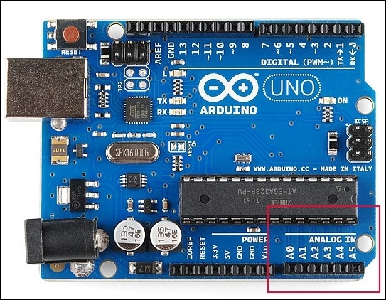
Arduino analog pins
Image source: https://cdn.sparkfun.com/assets/d/d/5/c/4/5114013ece395f527e000000.jpg
Let us see how to use this function by first interfacing our LDR and read its values to the serial monitor.