You now have all the know-how to build our safety box!
Let's start with the code:
//Initializing a variable to store the value of the button state
int lidState = 0;
int keyState = 0;
int lidPin = 2;
int keyPin = 3;
int alarmPin = 9;

// the setup function runs once when you press reset or power the board


void setup() {
  // initialize digital I/O pins
  pinMode(lidPin, INPUT);
  pinMode(keyPin, INPUT);
  pinMode(alarmPin, OUTPUT);
}

// the loop function runs over and over again forever
void loop() {

  lidState = digitalRead(lidPin);
  if ( lidState == LOW )
  {
    keyState = digitalRead(keyPin);
    if ( keyState == HIGH )
      digitalWrite(alarmPin, LOW);
    else
      digitalWrite(alarmPin, HIGH);
  }
  else
    digitalWrite(alarmPin, LOW);
}
We start by storing the pin numbers in variables so that it doesn't become confusing.
We then initialize the pins to be either input o
In the loop() function, you can see that we r output. In the loop() function, you can see that we have used the conditional if and else. which will make the Arduino make decide what to do.
Also, notice that inside the if statement that checks whether the lid of the box is open or not, there is another if statement that checks whether a key is inserted.
When multiple commands need to be executed after an if statement, the commands are put in between curly brackets {} , as seen in the preceding code, after the Arduino checks whether the lid is opened or not.
Now that we have the code ready, let's get our hands dirty with the electronics and hardware to build the safe! You will be making your own switches that will detect whether the box is open, or whether the key is inserted.
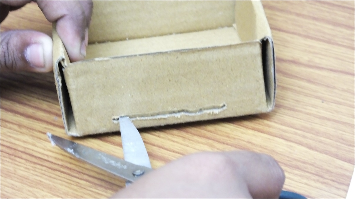
We start by making a slot in our box in the size of our keycard in an appropriate place:
We take a piece of aluminum foil and place it on the keycard:

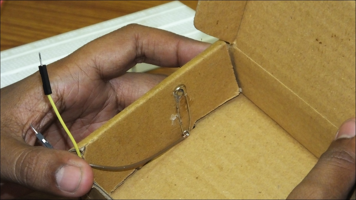
After cutting a male jumper wire, we strip the wire and tie it to a safety pin or a paperclip:

Make sure the wire is properly connected to the end so that it makes a good electrical connection.
The following image will give more clarity of the connections used in the model:
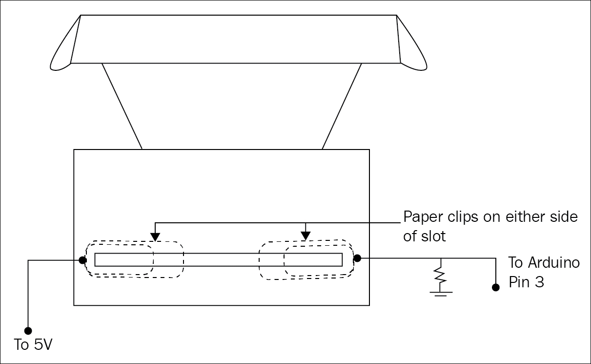
We glue-gun the safety pins to the inside of the box, such that they are exactly in the middle of the slot we earlier cut. The two safety pins we will glue need to be placed adjacent to each other with a small gap in between them:

The following image will give more clarity of the connections used in the model:
When the key card is placed in the slot, it will touch the two safety pins and complete the circuit similar to how a switch would work:
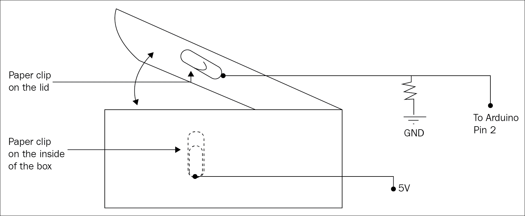
We do the same for the lid, placing one safety pin on the inside and another on the lid, such that when the lid is closed, a connection is made and the circuit would be complete:
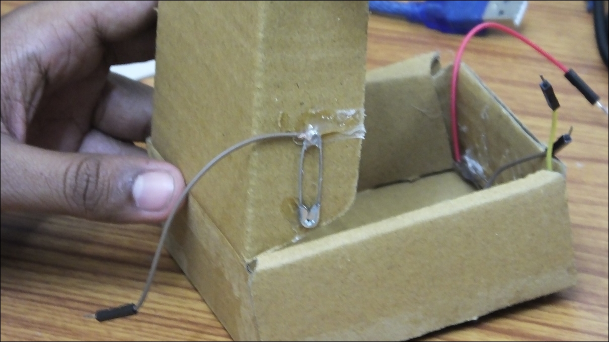
Hook up the wires coming from the safety pins to your circuit with the wire from one safety pin going into the 5V output of the Arduino, and the other into the Arduino's digital pin:

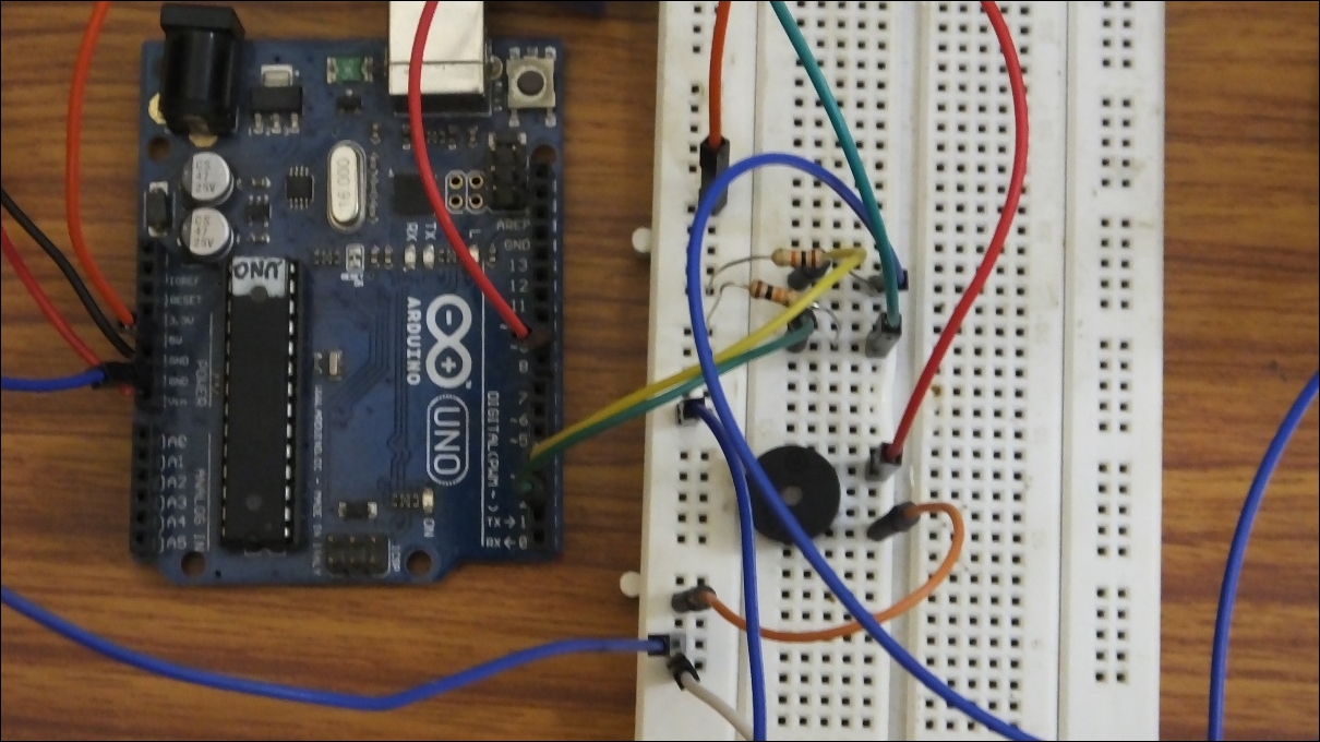
Finally, the complete connection looks like as follows: