

Job entry subsystem (JES3)
IBM's z/OS operating systems use a job entry subsystem (JES) to receive jobs into the operating system, schedule them for processing by MVS or z/OS, and to control their output processing.
There are two versions of the job entry subsystem concept, JES3 and JES2. Some principle differences between the two JES systems include:
•JES3 provides resource management, dependent job control, and deadline scheduling for users of the system, while JES2 in the same system would require its users to manage these activities through other means.
•In cases where multiple z/OS systems are clustered (a sysplex), JES3 exercises centralized control over its processing functions through a single global JES3 processor. The global processor provides all job selection, scheduling, and device allocation functions for all of the other JES3 systems in the sysplex. JES2 is that component of MVS that only provides the necessary functions to get jobs into, and output out of, the MVS system. JES2 is designed to provide spooling, scheduling, and management facilities for the z/OS systems in a sysplex.
With the z/OS MVS JES3 system, resource management and workflow management are shared between MVS and its Job Entry Subsystem 3 (JES3) component. Generally speaking, JES3 does resource management and workflow management before and after job execution, while MVS does resource and workflow management during job execution.
JES3 considers job priorities, device and processor alternatives, and installation-specified preferences in preparing jobs for processing job output. Features of the JES3 design include:
•Single-system image
•Workload balancing
•Availability
•Control flexibility
•Physical planning flexibility
1.1 What is a sysplex

What is a sysplex
A sysplex is a collection of MVS systems that cooperate, using certain hardware and software products, to process work. The term MVS - Multiple Virtual Storage - refers to the IBM operating system that manages resources and work flow for multiple jobs executing concurrently. A sysplex shares the processing of work across multiple MVS systems and lays the groundwork for simplified multisystem management through the cross-system coupling facility (XCF) component. XCF services allow authorized applications on one system to communicate with applications on the same system or on other systems.
The innate robustness and reliability of the MVS operating system and z/Architecture® processors are the foundation of a sysplex. That robustness and reliability are extended to all systems in a sysplex through cross system workload balancing and data sharing using the coupling technologies.
The sysplex increases the number of processing units and MVS operating systems that can cooperate, which in turn increases the amount of work that can be processed.
A major goal of operating systems is to process user work while making the best use of system resources. Thus, one way of viewing operating systems is as resource managers. Workload Management (WLM) - component of MVS - manages resources throughout a sysplex, WLM cooperates with resource managers that span systems. WLM uses customer-defined policies for performance objectives to help balance workloads in the sysplex.
What is a job
Job control language (JCL) is a set of statements that tell the z/OS operating system about the work (jobs) that is to be performed. Although JCL set of statements is quite large, most jobs can be run using a very small subset.
JCL statements tell z/OS where to find the appropriate input, how to process that input (that is, what program or programs to run), and what to do with the resulting output. All jobs use three main types of JCL statements:
•JOB statement to identify the unit of work you want the operating system to perform
•One or more EXEC statements, depending on the number of job steps within the job
•DD statements to identify the input and output data sets
What is a JES
MVS uses a job entry subsystem (JES) to receive jobs into the operating system, schedule them for processing by MVS, and to control their output processing.
Simply stated, JES is that component of MVS that provides the necessary functions to get jobs into, and output out of, the MVS system. It is designed to provide efficient spooling, scheduling, and management facilities for the MVS operating system.
The resource management and workflow management are shared between MVS and its JES component. Generally speaking, JES does resource management and workflow management before and after job execution, while MVS does resource and workflow management during job execution.
IBM provides two JESs from which to choose: JES3 and JES2. From job flow point of view JES3 and JES2 perform similar functions. That is, they read jobs into the system, convert them to internal machine-readable form, select them for processing, process their output, and purge them from the system.
JES3 exercises centralized control over its processing functions through a single global JES3 processor. This global processor provides all job selection, scheduling, and device allocation functions for all the other JES3 systems. The centralized control that JES3 exercises provides: increased job scheduling control, deadline scheduling capabilities, and increased control by providing its own device allocation.
JES2 exercises independent control over its job processing functions. That is, within the configuration, each JES2 processor controls its own job input, job scheduling, and job output processing.
1.2 JES3 LPAR sysplex - MULTISYSTEM

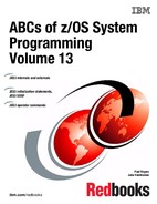
Multisystem sysplex
PLEXCFG=MULTISYSTEM indicates that the system is to be part of a multisystem sysplex consisting of one or more MVS systems that are running on one or more images. The same sysplex couple data sets must be shared by all systems in the sysplex
You must also specify a COUPLExx parmlib member through COUPLE=xx parameter that identifies the same sysplex couple data sets for all systems in the sysplex.
Use MULTISYSTEM when you plan to initialize one or more MVS systems into a multisystem sysplex and exploit full XCF coupling services. GRS=NONE is not valid with PLEXCFG=MULTISYSTEM.
With multiple MVS images in a single CPC environment using PR/SM™, PLEXCFG=MULTISYSTEM is the XCF mode required. A Sysplex Timer® is not required as PR/SM provides a common time reference, as shown in the figure. The JES3 systems communicate using XCF services, and the signalling services can be through either CTCs or the coupling facility.
A single system JES3 complex can be implemented in PLEXCFG=MONOPLEX sysplex. PLEXCFG=MONOPLEX indicates that the system is to be a single-system sysplex that must use a sysplex couple data set. Additional couple data sets, such as those that contain policy information, can also be used. XCF coupling services are available on the system, and multisystem applications can create groups and members. Messages can flow between members on this system (but not between this system and other MVS systems) via XCF signaling services. If signaling paths are specified, they are not used.
1.3 Multiprocessor JES3 sysplex
Multisystem sysplex
PLEXCFG=MULTISYSTEM indicates that the system is to be part of a multi-system sysplex consisting of one or more MVS systems that are running on one or more images. The same sysplex couple data sets must be shared by all systems in the sysplex
You must also specify a COUPLExx parmlib member through COUPLE=xx parameter in the IEASYSxx parmlib member that identifies the same sysplex couple data sets for all systems in the sysplex.
Use PLEXCFG=MULTISYSTEM when you plan to initialize one or more MVS systems into a multi-system sysplex and exploit full XCF coupling services. GRS=NONE is not valid with PLEXCFG=MULTISYSTEM.
When a multi-system sysplex is implemented in a single central processor complex (CPC) PLEXCFG=MULTISYSTEM is the XCF mode. A Sysplex Timer is not required. SIMETRID nn parameter on the CLOCKxx parmlib member specifies the simulated Sysplex Timer identifier. SIMETRID allows MVS images running on the same CEC, in native mode in LPARs, as VM guests, or combinations of these, to participate in a multi-system sysplex when no real sysplex timer is available. In these environments, the MVS TOD clocks are synchronized by PR/SM or the VM host. If a real sysplex timer is available, IBM recommends that you use it instead of SIMETRID.
The JES3 systems in a sysplex communicate using JESXCF services, and the XCF signalling services can be through either CTCs or the coupling facility.
With multiple MVS images in multiple CPCs, PLEXCFG=MULTISYSTEM is the XCF mode. A Sysplex Timer or IBM Server Timing Protocol (STP timing) provides the common time reference for the sysplex systems. The JES3 systems communicate using JESXCF, and the XCF signalling services can be through either CTCs or the coupling facility.
Couple data sets
A sysplex require a sysplex couple data set to store information about its systems, the XCF groups and members running in the sysplex, and general status information.
Depending on the policies you define to help manage resources and workload for the sysplex, you might need to define additional couple data sets to store policy-related information.
The coupling facility resource management (CFRM) couple data set holds the CFRM policy, which allows you to define how MVS is to manage your coupling facility resources.
The sysplex failure management (SFM) couple data set holds the SFM policy, which allows you to define how system failures, signaling connectivity failures, and PR/SM reconfiguration actions are to be managed.
The workload management (WLM) couple data set holds the WLM policy, which allows you to define service goals for workloads.
The automatic restart management (ARM) couple data set holds the policy that defines how MVS is to manage restarts for specific batch jobs and started tasks that are registered as elements of automatic restart management.
The system logger (LOGR) couple data set holds the policy that allows you to define log stream or structure definitions.
1.4 How JES fits into the MVS system

How JES fits into the MVS System
During the life of a job, both JES and the base control program of MVS control different phases of the overall processing. Generally speaking, job goes through the following phases:
•Input
•Conversion
•Execution
•Output
•Writer Processing (hard copy)
•Purge
Except for execution, all the job phases are controlled by JES.
Input phase
JES accepts jobs (in the form of an JCL input stream) from input devices such as card readers, remote terminals, or other programs. Input streams can also come from other nodes in a job entry network and from internal readers. An internal reader is a program that other programs can use to submit jobs, control statements, and commands to JES.
MVS also uses internal readers, allocated during system initialization, to pass to JES the job control language (JCL) for started tasks, START and MOUNT commands, and TSO LOGON requests.
As JES reads the input stream, it assigns a job identifier to each job and places each job's JCL, optional JES control statements, and SYSIN data onto DASD data sets called spool data sets. JES then selects jobs from the spool for subsequent JES processing phases and MVS execution.
Conversion phase
JES uses the MVS converter/interpreter programs to analyze each job's JCL statements. The conversion takes the job's JCL, merges it with JCL from a procedure library (such as SYS1.PROCLIB), and converts the composite JCL into internal format (scheduler work area (SWA) control blocks) that both JES and the job scheduler functions of MVS can recognize. JES then stores the output of the C/I processing on the spool data set. If any JCL errors are detected during the C/I processing JES issues messages, and the job is queued directly for output processing. If there are no errors, JES queues the job for the next JES processing phase. JES supports multiple converters; therefore, jobs may not always be processed in a first-in-first-out (FIFO) order. When MVS work load management (WLM) batch management is in use, JES queues jobs according to their arrival time.
Execution phase
In the execution phase, JES responds to requests for jobs from the MVS initiators. JES selects jobs that are waiting to execute and have required resources available.
An initiator is a system program that starts a job to allow it to compete for system resources with other jobs that are already running. The initiator JES communication is implemented through subsystem interface communication (SSI). Initiators are started and controlled by JES or by MVS workload management (WLM).
When an initiator requests work, JES selects a job and passes its SWA control blocks to the initiator. The job and its resource requirements are defined to the initiator by the SWA control blocks. A SWA is the internal representation of a job's JCL.
The initiator then allocates the resources specified in the JCL for the first step of the job and starts the program requested in the JCL EXEC statement for the first step. After the step ends execution, the initiator unallocates the step's resources and allocates the resources for the next step of the job. This process repeated for each step of the job.
Output phase
JES controls all SYSOUT processing. SYSOUT is system-produced output; that is, all output produced by, or for, a job. This output includes system messages that must be printed, as well as data sets created by the job that must be printed or punched. After a job finishes, JES analyzes the characteristics of the job's output in terms of its output class and printer device setup requirements; then JES groups data sets with similar characteristics. JES queues the output for writer (print or punch) processing.
Writer processing phase
JES writer processing selects output for processing from the output queues by output class, route code, priority, and other criteria. An output queue can have output that is to be processed locally or output to be processed at a remote location (either an RJE workstation or another NJE node). JES handles each of these situations in different ways. After processing all the output for a particular job, JES puts the job on the purge queue.
Purge phase
When all processing for a job completes, JES releases the spool space assigned to the job, making the space available for allocation to subsequent jobs. JES then issues a message to the operator indicating that the job has been purged from the system.
1.5 Subsystems

What is a subsystem
A subsystem is a service provider that performs defined functions when requested through the MVS subsystem interface (SSI). The SSI allow routines to request services of, or to pass information to subsystems. The SSI acts only as a mechanism for transferring control and data between a requestor and the subsystem; it does not perform any subsystem service functions itself. If the requestor of subsystem service does not identify the subsystem from which the service is wanted, the request is routed to the subsystem that initiated the job.
Service requests from IBM subsystems are identified by function codes. For example MVS initiators request JES job selection service with function code 5 and can expect the response format to be the same from JES2 and JES3. However, the internal job selection processing is implemented differently in JES2 and JES3. Thus, the SSI service requestor does not have to make any program changes when the service provider is changed.
Subsystems are defined to MVS in one of the following ways:
•In the IEFSSNxx parmlib member - Static definition
•Issuing the IEFSSI macro - Dynamic definition
•Issuing the SETSSI operator command - Dynamic definition
|
Note: The master subsystem (MSTR) is a part of MVS and is defined automatically during the MVS operating system initialization.
|
IBM subsystems
Some examples of IBM-supplied subsystems that provide services through the SSI:
•MSTR
•JES2
•JES3
•IMS™
•NetView®
•Tivoli® Workload Scheduler
Types of subsystems
There are four types of subsystems as follows:
•Master subsystem - One of the functions provided by the MSTR is the subsystem initiation service for the MVS initiator’s job select request during a subsystem start processing.
•Job entry subsystem - The job entry subsystem that MVS uses as default to select work from is defined also as a primary subsystem. The primary subsystem can be either JES2 or JES3.
•Secondary job entry subsystems - MVS allows more than one JES2 subsystems to operate at a time, as long as one subsystem is designated as the primary. The other JES2 subsystems are secondaries.
In JES3 complex secondary job entry subsystems are not supported.
•Other subsystems - Provide functions as needed by IBM products, vendor products, or the installation.
What is a functional subsystem?
A functional subsystem (FSS) is a collection of programs residing in an address space separate from JES that communicates with JES to provide a JES-related function, such as print processing and converter/interpreter (C/I) processing for JES3. An FSS extends the scope of JES processing. Because an FSS operates in its own address space, it functions independently of JES in several areas.
An FSS is responsible for:
•The management of storage resources that it needs during data set processing including print buffers.
•Its own recovery and serviceability.
•Its performance and accounting measurements.
•The security of its own resources.
JES and the FSS communicate through the functional subsystem interface (FSI) and SSI. The FSI is a one-level interface which provides two way communication. The FSI consists of a set of macro-invoked service routines provided by both JES and the FSS/FSA.
1.6 JES3 as the primary subsystem

JES3 as the primary subsystem
As the primary subsystem, the global JES3 plays an important role and the following functions provided by JES3 indicates why communication is needed between MVS and JES3. The global JES3:
•Introduces all jobs into the system, no matter what the source.
•Handles scheduling of conversion and interpretation of JCL.
•Performs pre-execution setup of devices.
•Schedules MVS jobs to all main processors.
•Maintains awareness of all jobs in execution.
•Handles the scheduling of all SYSOUT data sets for writer processing.
•Manages the allocation and deallocation of space on the shared-spool devices.
When carrying out some of these responsibilities, global JES3 needs the assistance of local JES3.
Functional subsystems
JES3 allows certain functions to operate outside the JES3 address space. JES3 does this using:
•The functional subsystem address space (FSS)
•The functional subsystem interface (FSI)
•The functional subsystem application (FSA)
WTR FSS
The JES3 FSS that deals with output services is one type of FSS (TYPE=WTR). This particular FSS address space may be created automatically or established by a CALL command for a printer device which is capable of running under the control of an FSS address space. The operator CALL command (*X) designates a printer as a "hot writer" while a writer invoked automatically when output is queued is called a "dynamic writer". A “hot writer” stays active until the operator stops it. A “dynamic writer” stops automatically after the specified time-out elapses if there is no more output to process.
CI FSS
Another FSS (TYPE=CI) deals with converter/interpreter services similar to those that occur in the JES3 global
The functional subsystem address space can be on any processor in the JES3 complex and is started by JES3 issuing the MVS START command with a token. When the first writer defined to a FSS is started, a functional subsystem address space is created. The operator can use the MODIFY command (*F) to change the processor where the FSS runs. When the operator stops a writer, JES3 stops the writer and when the last writer in the FSS address space is stopped the address space is terminated.
1.7 Defining subsystems

IEFSSNxx definition
The IEFSSNxx parmlib member contains parameters that define the primary and the various other subsystems that are to be initialized during the MVS system initialization.
IEFSSNxx allows:
•Name the subsystem initialization routine to be given control during MVS initialization.
•Specify the input parameter string to be passed to the subsystem initialization routine.
•Specify the primary subsystem name and whether it is started automatically.
During system initialization, the control structures that define subsystems to MVS are initialized. The recommendation is that you place the Data Facility Storage Management Subsystem (SMS) record before the primary subsystem’s (JES) record in the IEFSSNxx to start SMS before starting the primary subsystem. After the primary subsystem definition the other subsystems should be defined, because the other subsystems such as DB2®, require the services of the primary subsystem in their initialization routines. Problems can occur if subsystems that use the subsystem affinity service in their initialization routines are initialized before the primary subsystem. After the primary JES is initialized, then the other subsystems are initialized. in the order in which the IEFSSNxx parmlib members are specified by the SSN parameter in the IEASYSxx parmlib member.
SSN parameter
The SSN parameter in the IEASYSxx parmlib member identifies the IEFSSNxx parmlib members that the system is to use to initialize subsystems, as follows:
SSN=aa|(aa,bb,.......)
For example, for SSN=(aa,bb) parmlib member IEFSSNaa would be processed before IEFSSNbb.
IBM recommends that you use the keyword parameter form of the IEFSSNxx parmlib member. However, also the old positional parameter form of the IEFSSNxx parmlib member is supported.
SETSSI operator command
The SETSSI operator command can be used to add, activate, or deactivate subsystems dynamically after MVS system initialization.
IEFSSI macro service
An authorized program can dynamically control a subsystem with the IEFSSI macro service in any of the following ways:
•Add and define a subsystem to the system
•Activate a subsystem so that its function routines can process function requests
•Define a set of optional subsystem characteristics
•Deactivate a subsystem
•Swap the current SSVT with a new SSVT
•Store subsystem-defined data for a subsystem
•Retrieve subsystem-defined data for a subsystem that was previously stored with the put request
•Query information for all subsystems defined to the SSI
Subsystems have the choice of being dynamic. Subsystems that are not dynamic can be defined only at IPL using the positional form of the IEFSSNxx parmlib member and they cannot use dynamic SSI services.
Starting subsystems
Once a subsystem name is defined to the system, any attempt to start that subsystem (or any started task with the same name as that subsystem) with a START command which does not explicitly specify SUB=JESn will result in that subsystem or started task being started under the Master subsystem rather than under the job entry subsystem. Because the only procedure libraries available to the Master subsystem are those specified in the MSTJCLxx IEFPDSI data set, any procedures being started that are defined in the job entry subsystem's procedure library concatenation, but not in the MSTJCLxx IEFPDSI data set, will be unavailable. Therefore they will not be found and the START command fails.
Before a subsystem can provide services to the SSI calls it has to create its own subsystem vector table (SSVT) using the IEFJSVEC or IEFSSVT macro services. The SSVT defines the SSI functions supported by the subsystem.
The DISPLAY SSI operator command displays information about subsystem, dynamic or not, or about all subsystems.
1.8 Subsystem interface - SSI
Subsystem interface
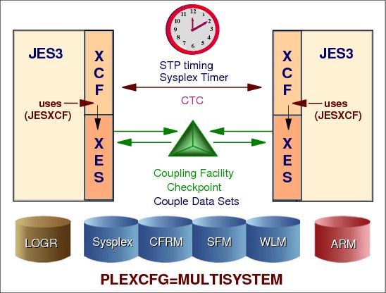
The subsystem interface (SSI) is an interface that provides intraprocessor communication between MVS routines and JES through the IEFSSREQ macro. The SSI is the interface used by routines (IBM, vendor, or installation-written) to request services of, or to pass information to, subsystems. An installation can design its own subsystem and use the SSI to request subsystem services.
|
Note: The SSI acts only as a mechanism for transferring control and data between a requestor and the subsystem; it does not perform any subsystem functions itself.
|
IEFSSREQ macro
MVS functions running in address spaces issue the IEFSSREQ macro to invoke subsystem functions. The calling routine uses the subsystem option block (SSOB), the SSOB function dependent area, and an optional subsystem identification block (SSIB) to identify the subsystem and requested processing. If the SSIB is not is not part of the IEFSSREQ parameters, the request is routed using the life-of-job SSIB. The life-of-job SSIB is created during the job initialization for the address space and contains a pointer to the JES control blocks for the job.
SSI control blocks
The major SSI control blocks are:
SSCVT Subsystem Communications Vector Table (SSCVT) maps information for defined subsystems
SSVT Subsystem Vector Table (SSVT) indicates the SSI functions supported by the associated subsystem
SSOB Subsystem Options Block (SSOB) identifies the requested SSI function. Passed as IEFSSREQ parameter to SSI
SSOB Function Dependent Area contains additional information, which can be passed to the subsystem along with the SSOB.
SSIB Identification Block (SSIB) identifies the particular subsystem to which a request is being directed. If a program does not provide an SSIB, the system uses the life-of-job SSIB.
1.9 SSI control blocks and routines

SSI control blocks and routines
The MVS nucleus contains control block named the JES control table (JESCT). This block contains pointer to the primary subsystem (JES) communication vector table (SSCVT), which is located in CSA.
IEFSSREQ macro
The IEFSSREQ macro provides communication between MVS and the target subsystem.
Before issuing the IEFSSREQ macro, the caller must ensure that register 1 points to the SSOB.
The calling routine uses the subsystem option block (SSOB), the SSOB function dependent area, and optionally the subsystem identification block (SSIB) to identify the required processing. The calling routine uses the IEFSSREQ macro to pass the SSIB and SSOB to the MVS SSI directed request router. The router locates the target subsystem’s SSCVT/SSVT pair and passes control to the requested subsystem function routine pointed from the SSVT.
JESCT JES control table (JESCT). A control block in the MVS nucleus that contains information used by subsystem interface routines.
SSCVT Subsystem communication vector table (SSCVT). These control blocks is the common storage area (CSA) and contain the information from subsystem definitions.
SSVT The subsystem vector table (SSVT). The SSVT resides in the common service area (CSA), is created by the subsystem, and contains the function matrix and function routine pointers.
SSOB Subsystem options block (SSOB). The control block which contains the SSI function code. The function code is used by the MVS SSI router to index into the SSVT matrix, The matrix entry contains an index to the subsystem function routine which is to get control as the result of the execution of the IEFSSREQ macro.
SSIB Subsystem identification block (SSIB). The control block into which the requestor of a subsystem function places the name of the subsystem from which service is requested.
Subsystem verification routine
This routine checks the validity of the SSOB and SSIB; the request routine determines that the target subsystem exists and is started. It next uses the function code to determine if the subsystem performs the requested function and to derive the address of a routine to which the request is to be passed.
1.10 Example: SSI request to master subsystem

SSI request to master subsystem
The verify subsystem function call (SSI function code 15) allows a program to:
•Verify the existence of a specific subsystem
•Obtain the address of the SSCVT that corresponds to a specific subsystem
•Obtain the subsystem affinity index value used when making subsystem affinity requests.
The MVS SSI directed request router (IEFJSREQ) routine checks the validity of the SSOB and SSIB; the request routine determines that the target subsystem exists and is started. It next uses the function code to determine if the subsystem performs the requested function and to derive the address of a routine to which the request is passed.
1.11 JES3 complex - sysplex

JES3 complex in a sysplex
A sysplex is a set of MVS systems communicating and cooperating with each other through certain multisystem hardware components and software services to process customer workloads. A sysplex can have up to 32 MVS systems.
The cross-system coupling facility (XCF) provides the MVS coupling services that allow authorized programs on MVS systems in a multisystem environment to communicate (send and receive data) with programs on the same MVS system or other MVS systems. The cross-system extended services (XES) allow authorized programs on MVS to use a coupling facility to share data with other programs on the same MVS system or other MVS systems. The eventual goal for the coupling services provided by XCF and XES is to allow an installation to view multiple MVS systems as one MVS system.
Each sysplex is given an XCF sysplex name (in the visual SANDBOX) and each system in the sysplex has a unique name as well. The COUPLExx parmlib member for each system in the sysplex is used to specify the installation values for sysplex systems.
A JES3 complex must be fully contained within a sysplex and may or may not be the primary subsystem for all the MVS systems in the sysplex.
|
Note: Each JES3 complex in a sysplex is required to use a unique JES XCF groupname (in the visual WTSCPLX4). The NAME parameter on the NJERMT statement that defines HOME=YES is the default for the XCFGRPNM parameter on the OPTIONS statement.
|
XCF and JESXCF
In a JES3 complex one of the JES3 processors is designated as the focal point for the entry and distribution of jobs and for the control of resources needed by the jobs. That processor, called the global processor, distributes work also to all other processors, called local processors. The global processor and the local processors communicate using the MVS cross-system coupling facility (XCF) through the JES common coupling services (JESXCF) component. Among other things, the JES3 inter-processor communication is used to extend the intra-processor SSI communication from local processors to the global which provides the services for most of the SSI calls.
The JES3 global processor manages jobs and resources for the entire complex and selects jobs with readily available resources for MVS execution. The resources that JES3 manages include processors, I/O devices, spool volumes, the job queue, the checkpoint data set, and sysin/sysout data. To avoid job execution delays that result when resources are not available, JES3 ensures that they are available before selecting the job for processing.
JES3 terminology
In the JES3 terminology a processor is defined as a hardware unit that contains software to interpret and process instructions.
Global processor The processor that controls job scheduling and device allocation for a complex of processors. See also local processor.
Local processor In a complex of processors under control of JES3, a processor connected to the global main by a JESXCF services, for which JES3 performs centralized job input, job scheduling and job output services by the global main.
Main A processor named by a JES3 MAINPROC initialization statement, on which jobs can execute; represents a single instance of MVS. The two types of mains are global main, and local main.
Global main The global main controls job scheduling and device allocation for a complex of JES3 processors. Each local main in the complex exists under control of the JES3 global main and is connected to the global main by JESXCF services. The JES3 on the global main can perform centralized job input, job scheduling, and job output services. Only the global main performs scheduling functions, although scheduled work executes on the local mains.
Local main In a complex of processors under control of JES3, a processor connected to the global main by a JESXCF services, for which JES3 performs centralized job input, job scheduling and job output services by the global main.
1.12 JES3 global benefits

JES3 global processor
It is from the global processor that JES3 manages jobs and resources for the entire complex, matching jobs with available resources. JES3 manages processors, I/O devices, volumes, and data. To avoid delays that result when these resources are not available, JES3 ensures that they are available before selecting the job for processing.
JES3 provides installation benefits from the distribution of work among processors as a workflow manager. The entry of all jobs through a central point means that control of the actions needed to prepare jobs for execution can be centralized. The distribution and duplication of job management function becomes unnecessary, and an awareness of the status of all jobs entering or leaving the system can be easily maintained. This awareness is particularly useful in recovery situations, where the scope of recovery is largely a function of the quality of the tracking performed prior to the failure.
Resource manager
Another benefit is resource management. All jobs, all input required for the jobs, and all output produced by the jobs enters or leaves the system at a single point. This single point, JES3, can coordinate the subsystem, the allocation of devices, volumes, and data sets. Centralized resource control expands the opportunity for full resource utilization. If you are using the storage management subsystem (SMS), you can allow SMS to coordinate the allocation of permanently resident catalog volumes and cataloged data sets. When SMS is activated, JES3 will not manage devices and volumes for SMS-managed data sets.
JES3 keeps track of I/O resources, and manages workflow in conjunction with the workload management component of MVS by scheduling jobs for processing on the processors where the jobs can run most efficiently. At the same time, JES3 maintains data integrity. JES3 will not schedule two jobs to run simultaneously anywhere in the complex if they are going to use the same serially reusable resources. If you want to share input/output (I/O) devices among processors, JES3 manages the sharing. Operators do not have to manually control the online/offline status of devices to keep up with changing processor needs for the devices.
Operations aid
Operator control also benefits from improved resource utilization and centralized job management. With all system resources known to JES3 and with one job management mechanism, it is relatively simple to provide control over the entire system. And yet, the need for operator control can be minimized because JES3 is aware of job mix and resource availability and can coordinate them with less need for operator intervention and decision-making.
Operators have special JES3 commands. Some commands activate programs to handle I/O devices, while others obtain or change the status of jobs being processed. With multiple processing-unit systems, JES3 operators have less to do than for an equal number of individual systems, because they can control the entire complex from a central point, and because JES3 decides where and when jobs will be processed.
For diagnostic purposes, JES3 provides traces and dumps. Traces are copies of data made during normal processing to help monitor activity in the system, and dumps are copies of data made at times of failure.
1.13 JES and JESXCF communication

JES and JES XCF processing overview
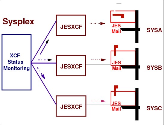
JESXCF is an XCF multisystem application and provides, based on XCF coupling services, common inter-processor and intra-processor communication services for both JES3 and JES2 subsystems. The JESXCF services are tailored to meet JES specific requirements and are provided through macros that enable communication among JES members in a sysplex. The macros are available to either JES3 or JES2 and can be used only in JES environments, except for the send message service, which can be used in all environments.
JESXCF address space
The JESXCF address space is created during the first JES initialization on that system. As each JES is initialized, it joins the JES XCF group for the JES complex in which the newly initialized JES will be a member. After all JES members have successfully joined an XCF group, JES routines running on that JES member can use the JES common coupling services to communicate with the other JES members in the same JES XCF group. There are a number of restrictions that apply to JES XCF groups and their use. These include:
•The JES common coupling services component and its exits and macros are not available outside either a JES2 or JES3 environment.
•The JES systems in the JES XCF group must be either all JES2 or all JES3
•All JES2 multi-access spool (MAS) members or JES3 complex mains must join JES XCF if they are to communicate.
•All JES2 MAS members or JES3 mains must be members of the same sysplex.
There is one JESXCF address space in each MVS image and it acts as a server address for all JESes in a given MVS system.
JES3 initialization processing
During JES3 initialization, the JES XCF attach/detach exit receives control under the JES main task. At this time, the JES member is attached automatically to the JES XCF group. Each member has a different name, but each is attached to the same group to form the JES XCF group, thereby allowing each to communicate (send messages, obtain member and JES XCF group status, and so on).
JES3 message processing
Each JES3 member is in constant communication with every other JES3 member of its JES3 complex. In JES3, there is a continuous flow of SSI requests -- allocation requests, system status, job status, work requests, and so forth -- that is needed to properly coordinate the work JES3 is putting into and taking out of the MVS system. These pieces of communicated data are considered messages, and each causes the invocation of two JES XCF exits: the transport exit and the receive exit.
Exit IXZXIT01, called the transport exit, gets control whenever JES or installation code sends a message. JES XCF packages the message data in an envelope that contains the address information and other related data, and sends it to a specified mailbox.
Once a message is sent to a mailbox (on the same member or another), the receiving member is informed that mail is waiting. After the receiving member issues the receive macro, IXZXIXRM, the receive message exit IXZXIT02 gets control. This exit allows the receiving member to view or modify the message and to receive any extents that have been added to it by the transport exit. Once the message is received, the receiving member acknowledges the mail, informs JES XCF of its receipt and, if requested by the sending member, also returns an acknowledgement to the sender.
JES3 termination processing
During JES3 termination processing only JES3 FSS provide clean up when terminating normally. The JES3 termination (*RETURN) does not invokes the detach macro.
Therefore, JES3 FSS normal termination only issues the detach macro, IXZXIXDT. IXZXIT03 receives control as a result of the IXZXIXDT macro call and does clean up.
|
Note: In a JES3 environment to restart the JESXCF address space a MVS IPL is required to recover critical resources.
|
1.14 JES3 and JESXCF initialization

JES3 and JESXCF initialization
During the JES3 initialization or the JES3 FSS connect processing, the JESXCF attach service is invoked through the IXZXIXAT macro. The JESXCF attach service creates an address space for JESXCF if it does not already exist and attaches the JES3 member to a JESXCF group. During the JESXCF attach processing, the MVS XCF group services are invoked (using IXCJOIN macro) to create an XCF member for the JES3 member. JES3 uses as the XCF group name the XCFGRPNM= specification from the OPTIONS initialization statement when present. Otherwise the NJE home node name is used. The default name for the home node is N1.
JES3 uses as the XCF member name the name defined on the NAME= parameter on the MAINPROC initialization statement. The JES3 FSSs use as the XCF member name the FSSNAME= specification on the FSSDEF statement.
|
Note: Ensure that the name you specify on the MAINPROC initialization statement matches the name specified on the SYSNAME parameter in the IEASYSxx parmlib member used for MVS IPL. Otherwise JES3 initialization will fail.
|
Installations may create their own independent attachments to JESXCF. If an installation-defined JESXCF group is required, it should be created in the JESXCF attach/detach exit IXZXIT03 during the JESXCF attach/detach processing.
A successful attach JESXCF group request returns a JESXCF group token. All subsequent JESXCF service requests require this group token as input.
1.15 JESXCF communication flow

JESXCF communication flow
The JESXCF communication is in the form of messages. In the JESXCF context, a message is any data, including XCF events, that comprises a data packet. A data packet is the data that one JES3 member sends to itself or another member within the JESXCF group. The maximum size of the data is 60KB. If the quantity of data being sent is larger than 60KB, it can be broken into parts and transported as a multi-segment message.
JESXCF messages are received through mailboxes. A mailbox is a logical queue of ordered messages and is maintained by JESXCF in a location associated with a JES3 member. Messages are held in mailboxes until the receiving JES3 receives them or clears the mailbox. When a message is received, it is preceded by a message envelope. The message envelope is the header for the message and contains information that includes:
•The addresses of the sender and receiver of the message
•An identifier of the message type
•An offset to the actual message
Envelopes, mapped by IXZYIXEN macro, are for the following types of messages in a mailbox:
•System events (SYSEVENT)
•Acknowledgements (ACKS)
•Messages (MESSAGES)
The message envelope includes information such as:
•Status of the message in the mailbox:
– Message has been resent to the receiving system because the system was re-IPLed.
– Message has been rerouted.
– Message was present in the mailbox when the attacher disconnected.
– Message has been received.
– Message has been checkpointed.
•Maintenance level of the JESXCF component
•Message sequence number
•Address information of the receiver of the message (group name, member name, and mailbox name)
•Address information of the sender of the message (group name, member name, and mailbox name)
•Type of the send message request:
– Synchronous message
– Asynchronous message that does not return an acknowledgement to the sender
– Asynchronous message that returns an acknowledgement message to the sender
– Asynchronous message that will not be resent to the receiver if the receiving system re-IPLs. No acknowledgement will be sent to the sender of the message
– Acknowledgement message
– Acknowledgement message sent because time specified on the on the IXZXIXSM macro has expired
•Single segment or multi-segment message indicators.
•Content of the message:
– A system event
– An acknowledgement message
– Application message
•Length of the message not including the envelope
Acknowledgement (ACK)
An acknowledgement provides notification information on delivery of messages issued through the IXZXIXSM macro service. The acknowledgement data includes:
•Request token for the message that this acknowledgement is for
•Return code information returned by the receiving routine
•Length of the data returned to the sender through the IXZXIXAC macro service
User data (MESSAGE)
JESXCF does not impose any format requirements on user data.
•System Event (SYSEVENT)
The system event data includes three types of system event data:
•JESXCF Data (IXZYIXIF) - JESXCF data provides information about the JES and XCF connections, such as notification of an event detected by the JESXCF address space or such as termination of the connection between JESXCF and the JES address space.
•JES Data (IXZYIXJE) - JES data provides a notification of events that the JESXCF address space has detected, such as termination of the connection between JESXCF and the JES address space. The JESXCF event data:
– Connection between JESXCF and specified JES terminated
• Group name of the member whose connection terminated
• Member name of the member whose connection terminated
• The request token for the message that timed out
•XCF Data (IXCYGEPL) - The XCF data is the same that is passed to the XCF group user exit of an active member. XCF data notifies about changes that occur to the XCF members of a group, or changes to the systems in the sysplex.
1.16 JESXCF status monitoring
JESXCF status monitoring
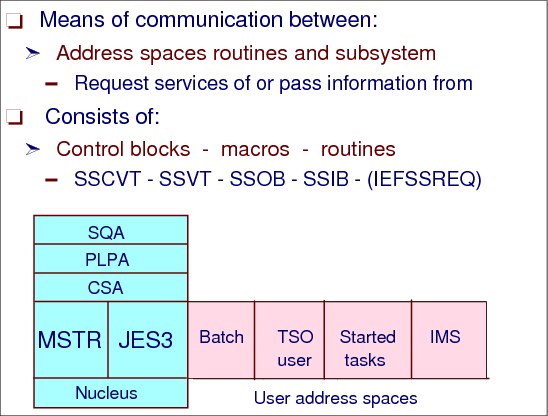
Status monitoring services - Status monitoring services are authorized services that notify member exit routines (the group exit routine) of changes to the status of other members of their group and the systems in the sysplex. Members can request that XCF monitor their activity (the status exit routine).
There are two kinds of monitoring services in XCF:
•System status monitoring
System status monitoring services monitor systems in the sysplex. The monitoring function uses the system status fields, which are periodically updated. All active application group exits receive control if a system fails to update its status field within a defined interval.
•Member status monitoring
Member status monitoring lets a member actively monitor its status. The services are optional, but if a member does use the services, then it has to update its status field periodically. The member status exit gets control if the member fails to update its status field within a specified interval. When the member status exit confirms that the member's state changed, XCF notifies other members about the change through the group exit routines.
1.17 JESXCF macro services

JESXCF macro services
The following JESXCF macro services are available:
IXZXIXAT During JES3 initialization, each member attaches to a JESXCF group and identifies itself by a unique member name and a JESXCF group name representing the whole JES3 complex.
IXZXIXMB JES3 functions that intend to receive messages must build a mailbox (a logical queue of ordered messages that is maintained by JESXCF). This also implies that all JES3 functions that are to receive the JES3 global initiated communication (for example FSS order processing) must create a mailbox. When a JES3 function retrieves and acknowledges a message, JESXCF removes that message from the mailbox. A mailbox may also be cleared (IXZXIXMC) without receiving queued messages. When a mailbox is cleared, JESXCF acknowledges those messages it clears.
When JESXCF returns control after a successful attach JESXCF group request, a default mailbox (named SYSJES$DEFAULT) is supplied. This mailbox collects system event data. System event data includes any XCF events on any JES3 member of the JESXCF group and events on the MVS system under which it runs. JES3 does not use the default mailbox and deletes it.
IXZXIXSM The JESXCF send a message service sends a data packet to the same or another JES3 function in the same JESXCF group. A send message request can be issued from a function running under a JES3 main task, a JES3 subtask, JES3 FSS address space, or a user address space. Once a message is sent, JESXCF delivers the message to the requested receiver.
JESXCF maintains the order of the messages sent. All messages are received in the order in which they are sent. Multi-segment messages are not sent until the entire message (all segments) is available.
The message sender identifies the destination of the message by supplying the member name and the mailbox name of the receiver. This receiving member can be any member of the JESXCF group, including the sending member.
IXZXIXRM Once a message is sent to a mailbox, the receiving member is informed through the POST exit routine. This posting action notifies the mailbox owner of a message to receive.
IXZXIXAC All received messages must be acknowledged to JESXCF independent of whether the sender requested an acknowledgement or not. After a message is acknowledged, JESXCF releases all resources held by the original message.
If the sender of the message requests an acknowledgement, the JESXCF returns an acknowledgement message as follows:
•To the mailbox specified on the ASYNCACK type send request as the mailbox into which the acknowledgement message is to be returned
•To the area specified on the SYNC type send request
IXZXIXIF The request JES3 member information service (IXZXIXIF) returns a record of data about the specific group member, and also information about the MVS system on which the member is running. The data is returned either through a mailbox or is placed directly into the requestor's data area in an array format. If the data is returned to the mailbox, JESXCF treats it as system event data.
The returned member information includes:
•Request token that was returned from IXZXIXIF service
•The release level of the JES product and JESXCF maintenance level
•XCF group name and member name
•MVS system name that the JES is running on
•User state information as set by IXZXIXUS macro service
•XCF member token and XCF sysplex token
Member status:
•Member is active, connection between the JESXCF address space and the JES address space is functioning.
•MVS XCF state of the member is active but the connection between the JESXCF address space and the JES3 address space is not functioning. The probable cause is a JES3 abend.
•Both MVS XCF status and JESXCF connection status indicate that the member is not active.
IXZXIXDT The detach from a JESXCF group service (IXZXIXDT) deactivates and removes a JES from an XCF group.
The JES3 FSS/FSA Connect/Disconnect SSI routine invokes IXZXIXDT during FSS disconnect processing. JES3 mains do not detach from the JESXCF group during JES3 termination.
1.18 JESXCF user exits

JESXCF user exits
JESXCF provides the following user exits:
•IXZXIT03 - If an installation-defined JESXCF group is required, it should be created in the JESXCF attach/detach exit IXZXIT03. Exit IXZXIT03 receives control during the JESXCF attach/detach processing. Care should be taken not to inadvertently cause JESXCF to enter a recursive loop caused by the attach service calling the attach exit.
Exit IXZXIT03 receives control during the IXZXIXAT JESXCF processing, and it may obtain a data area for later IXZXIT01 and IXZXIT02 processing, or it may provide an additional attachment to JESXCF. The IXZXIT03 exit receives control after the JES3 member has joined an XCF group but before either IXZXIT01 or IXZXIT02 receives control.
During detach processing, IXZXIT03 receives control to free the data area obtained during the attach processing or to drop the attachment from JESXCF. After IXZXIT03 receives control, neither IXZXIT01 nor IXZXIT02 receive control for the XCF group from which JES3 is detaching.
Exit IXZXIT03 communicates with JESXCF by setting flag bits and changing data fields in the parameter list passed to the exit.
•IXZXIT01 - Exit IXZXIT01 enables you to view, modify, add to, or reroute a message prior to the message being delivered to the receiving member. This exit gets control for the send message and the acknowledge message macro invocations.
Exit IXZXIT01 receives control under the same task that issues the IXZXIXSM or IXZXIXAC macros. JESXCF invokes the exit after a message packet has been created but before that packet is sent to its target member, and when the acknowledging member replies to the originating system for all acknowledgements except for the request COMM type message acknowledgements.
The data passed to this exit is in a data space; therefore, the data can be accessed through an access register. The exit receives control in access register address space control (AR ASC) mode. AR1 contains the ALET of the data space containing the exit parameters.
•IXZXIT02 - When the receiving function issues the receive macro, IXZXIXRM, the receive message exit (IXZXIT02) gets control first. This exit allows the receiving member to view or modify the message and to receive any extents that have been added to it by the transport exit. Once the message is received, the receiving function acknowledges the mail, informs JESXCF of its receipt, and if requested by the sending member, also returns acknowledgement data to the sender.
The receiver of a message must:
– Provide the group token that represents the JESXCF member and group
– Identify the mailbox from which to retrieve the message
– Indicate the type of message to be received:
• Only system event messages
• Only acknowledgement messages
• Only JES- or installation-created messages
Each segment of a multi-segment message is presented as a single message, and all segments are ordered as originally sent. However, individual messages from multiple members might not be ordered in the mailbox in a timestamp order.
Samples of these exits can be found in SYS1.SAMPLIB.
1.19 XCF signalling paths
XCF signalling
XCF signaling services are the primary means of communication between members of an XCF group. XCF provides the following macros for sending and receiving messages:
•IXCMSGO - Allows members to send messages to other members in their group
•IXCMSGI - Allows the message user routine to receive messages sent from a member. When a member joins an XCF group, it must specify the address of a message user routine to be given control when another member sends you a message.
•IXCMSGC - Allows members to interact with the signalling services for enhanced signaling functions.
XCF groups
A group in XCF is defined as the set of related members defined to XCF by the multisystem application (for example, JES3). A group can span one or more of the systems in a sysplex and represents a complete logical entity to XCF.
JES3 mains join the sysplex using JESXCF services. Communications between JES3 mains are through JESXCF signalling services. JESXCF uses XCF signaling services for communications, XCF uses whatever connections are configured to z/OS, which could be the coupling facility or ESCON® CTCs.
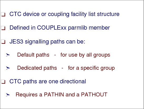
XCF signalling paths
An XCF signalling connection consists of at least two operational signalling paths (one inbound and one outbound); a signalling path can be any combination of a coupling facility list structure, an ESCON CTC channel (SCTC control unit), or a CTC through a Multisystem Channel Communication Unit.
Implementing XCF signaling through coupling facility list structures provides significant advantages in the areas of systems management and recovery and, thus, provides enhanced availability for sysplex systems.
While a signaling path defined through CTC connections must be exclusively defined as either outbound or inbound, you can define a coupling facility list structure so that it is used for both outbound and inbound signaling paths, and MVS automatically establishes the paths. For example, if you define a list structure for outbound message traffic, MVS automatically establishes a signaling path with every other system that has the structure defined for inbound message traffic. Similarly, if you define a list structure for inbound traffic, MVS automatically establishes a signaling path with every other system that has the structure defined for outbound traffic.
Signaling paths implemented through CTC connections are one directional. That is, on each system, messages sent to other systems require an outbound path, and messages received from other systems require a separate inbound path.
Communication paths
An XCF communication path is determined by the PATHIN and PATHOUT definitions initially defined in the COUPLExx parmlib member. The definitions can be modified with the SETXCF operator command.
|
Note: Two paths are recommended between systems.
|
1.20 JES3 SSI communication implementation - user to JES3
SSI communication - user to JES3
The subsystem interface (SSI) function routines and the JES3 subtasks use the SSISERV macro service to communicate with the global JES3. There are several types of SSISERV requests:
•COMM - Specifies that the request is for communication only. The data area address must be contained in a data area called JES3 subsystem communications service entrance list (SEL). The SEL is the parameter list for the SSISERV service.
•WAIT - Specifies that a response is required and that the routine is to wait until the response is received. The data area, ECB, and buffer addresses must be in the SEL.
•REPLY - Specifies that a response is required but the routine is not to wait for the response. The data area address must be in the SEL.
•ACK - Specifies that the request is for communication and that the request requires an acknowledgment. The RESP subparameter is used to make the acknowledgment.
•RESP - Specifies the answer to a WAIT or REPLY request, or the acknowledgment to an ACK request. The staging area address is required. If you specify TYPE=RESP, do not specify the FUNC parameter.
•PURGE - Specifies that a staging area that had been routed to the requester is to be deleted. The staging area address in the SEL is required. If you specify TYPE=PURGE, do not specify the FUNC parameter.
•EOMT - Specifies the special interface from EOM/EOT SSI for staging area cleanup. The data area address in the SEL must contain the address of the SSIB/SSOB control block pair.
The service routine for the SSISERV macro requests is IATSSCM. It builds a staging area from the information provided in the SEL and calls JESXCF to send the request JES3. The JSERV macro provides communication between JES3 and a user or functional subsystem (FSS) address space, between JES3 on one processor and JES3 on another processor, and between FCTs in the same JES3 address space. The IATSSJS service routine converts parameters from a JSERV macro to those required by SSISERV and then issues the SSISERV request.
Staging areas
The data area JES3 uses in the SSI communication is called a staging area (IATYSTA). It contains the data describing requests for JES3 services, for transport to and from JES3 and related address spaces. When JES3 passes a staging area to JESXCF for transportation, JESXCF wraps an message envelope around the staging area. The envelope (IXZYIXEN) provides header and control information about messages being sent between JES software components.
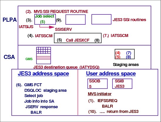
Steps shown in the visual
The following steps are shown in the visual.
Step 1 An MVS initiator issued a function code 5 job select request. A subsystem options block (SSOB), contains a function code that defines the request being made. The SSOB also contains the address of the subsystem identification block (SSIB), which identifies the subsystem to which the request is to be sent (in this case JES3). The expansion of the IEFSSREQ macro contains instructions to cause entry to the MVS request router routine IEFJSREQ.
Step 2 The MVS SSI request router routine get control, verifies the validity of the request, and for a valid request passes control to the subsystem’s (JES3) job select SSI routine.
Step 3 The function code 5 (Job Select) routine, IATSIJS, gets control. IATSIJS builds a SEL for job select queue element (JSQ) to be passed to generalized main scheduling (GMS - active on the global processor). IATSIJS obtains a storage area to be used for the response buffer for the SSISERV TYPE=REPLY macro request that will pass control to the JES3 subsystem communication services (IATSSCM).
Step 4 Module IATSSCM validates the SSISERV request, determines the JESXCF member (the global) and the mailbox to receive the request. The request is sent to JESXCF with IXZXIXSM macro service specifying the requester's response buffer as the area to be used to receive the response data. After passing the request to JESXCF IATSSCM waits for the response.
Step 5 JESXCF sends the message to the destination member. Once the message arrives at the destination, JESXCF on that member invokes the JES3 main processor mail box post exit routine in JES3 subsystem communications read end module (IATSSRE). The post exit routine posts the JES3 job selection function (GMS) associated with the JES3 main that issued the job select SSI request. The JES3 nucleus task is also posted for work.
Step 6 The GMS function (IATMSMS), posted (in step 5) to process a job select request, retrieves the incoming requests with the JES3 DSQLOC macro service. The DSQLOC macro invokes JES3 subsystem communication destination queue services module (IATSSDQ). IATSSDQ makes calls to the JESXCF receive message service (IXZXIXRM) to receive each message that has been sent to the mailbox. Messages are unwrapped and all information about the message that JES3 needs to know (such as if the message was resent, or if the sending member was restarted) will be propagated into the staging area. The staging area will be queued to the end of the target destination queue's staging area queue. IATSSDS routine then returns to the caller, passing back the address of the first staging area. Once GMS finds a job for the job select SSI request, a reply is send back to the requestor with the JSERV macro service implemented in JSERV conversion routine (IATSSJS). IATSSJS invokes the SSISERV service which passes the response back to the requesting main processor.
Step 7 On the requesting main the IATSSRE routine gets control, it copies the response data to the response area obtained by the ITASIJS function and posts the waiting function IATSSCM routine.
Step 8 The IATSSCM routine resumes processing and returns to the job select SSI routine IATSIJS.
Step 9 IATSIJS updates the SSOB and the SSOB’s function dependent area (SSJS) with the job select information returned from the global JES3.
Step 10 IATSIJS returns control to the initiator.
1.21 SSI communication implementation - Global / Local
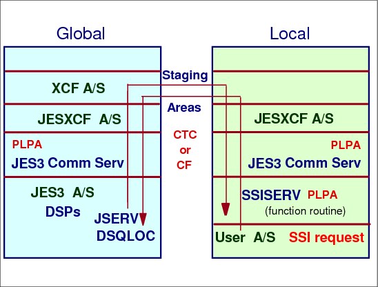
Global - Local communication
When a SSI request comes from an address space on a local main, the flow is the same as in the last figure until step 6. Since the GMS function is on the global processor, it is necessary to send the staging area to the global. JESXCF uses XCF to move the staging area across the CTC to the global. XCF on the global receives the request and uses JESXCF to pass the staging area to IATSSCM. The staging is then placed on the destination queue of GMS.
GMS selects a job and uses the JSERV macro to pass the data in a staging back to the address space on the local. After a function has been posted that an SSISERV request has arrived for it to process, the function uses the DSQLOC service to get the request. DSQLOC adds any new requests to the existing DSQ staging area queue, and returns the first request on the queue to the caller. The caller can then process the first request, or run the queue to determine which request it wants to process. When the request is processed, the JSERV service is then used to purge it, or to send a response back to the original requester.
When JSERV or SSISERV is called, JESXCF takes the information provided by the requester and builds a staging area. Then, based on the request type, it calls a JESXCF service to build a JESXCF message out of the staging area and then transport the message to its destination.
1.22 JES3 SSI functions
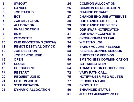
JES3 SSI function
The JES3 SSVT mapping macro IATYSVT contains a list of the JES3 supported SSI function codes. In the SSVT area, followed by the MVS function code matrix and address list, JES3 maintains its own data (queue anchors and address constants). The “extension data” is mainly used by the JES3 routines that execute outside the JES3 address space. For example the JES3 destination queue (DSQ), a control block used by subsystem interface routines to route requests to the JES3 functions responsible for servicing the requests, is pointed from the JES3 SSVT extension.
1.23 SSISERV function codes and JES3 destination queue
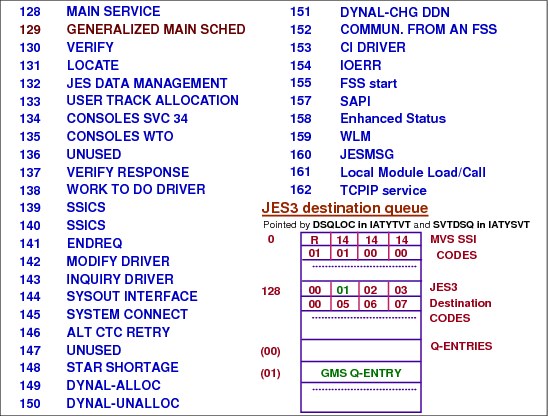
SSISERV function codes and JES3 destination queue
The subsystem interface (SSI) function routines and the JES3 subtasks use the SSISERV macro to communicate with JES3. The FUNC= keyword parameter specifies either the subsystems options block (SSOB) function code of the requester or, if the originator is JES3, a JES3 destination code. The actual data transportation requested by the SSISERV macro is done by JESXCF. Once the JESXCF message arrives at its destination, the staging area in the message envelope is queued into the JES3 destination queue.
Destination queue
The JES3 destination queue (DSQ) is a control block used by subsystem interface routines to route requests to the JES3 functions responsible for servicing the requests. The DSQ control block is made up of a queue index section and followed by the queue entry section. In the queue index section offsets 00 - 7F are SSOB function codes and offsets 80 - FF are JES3 destination codes. An index entry byte used to calculate the offset into the corresponding queue entry. The queue entries include: event completion flag (ECF) and mask, entry status flags, pointers to the first and last staging are on the queue, and the JESXCF mailbox name.
SSISERV service macro
When SSISERV service routine (IATSSCM) calls JESXCF to transport a staging area, it provides JESXCF with the name of the mailbox to receive the message envelope wrapping the staging area. Later, when the target JES3 function invokes the DSQLOC service (IATSSDS) to receive the staging area, the JESXCF receive message service (IXZXIXRM) is invoked. All messages that have been sent to the mailbox corresponding to the destination queue entry are received and unwrapped.
Staging area
All information about the message that JES3 needs is propagated into the received staging area, and then the staging area is queued to the destination queue's staging area queue. The address of the first staging area on the queue is passed to the caller on return from the DSQLOC service.
The destination queue table (IATYDSQ) is built during JES3 initialization. The table can contain a maximum of 256 entries.
DLOCON macro
Issuing the DLOCON macro enables a function in the JES3 global or local address space to receive unsolicited communication (staging areas) from a user's address space, from JES3 on another processor in the processor complex, or from an FSS or FSA in another address space. The DLOCON service routine (IATSSDS) marks the requested destination queue entry as active, and save in it the input ECF address and mask. It also creates a JESXCF mailbox for the DSQ entry with the JESXCF IXZXIXMB macro. The mailbox name is also set into the destination queue entry. When a JESXCF mailbox is created, a subroutine in IATSSRE is specified as the JESXCF post exit routine for the mailbox.
1.24 JES3 destination queue - IATYDSQ

Destination queue entries
During JES3 initialization, the destination queue table (IATYDSQ) is built. The table can contain a maximum of 256 entries. Each entry in the destination queue table is a queue of staging areas that are waiting to processed. A single entry in the destination queue is used for all staging areas that were sent to be processed by that function for which the destination queue was built for.
The destination queue entry has the pointers to the staging areas waiting to be processed.
JESXCF mailboxes are used to manage SSISERV requests received by the JES3 address space. A JESXCF mailbox is created the first time DLOCON is called, and is used to receive requests associated with the DSQ entry indicated by the caller.
When SSISERV calls JESXCF to transport a staging area, it provides to JESXCF the name of the mailbox in which to place the message. When the DSQLOC service is called to process a DSQ, it receives all outstanding staging areas from the JESXCF mailbox associated with the DSQ. These staging areas are queued to the DSQ staging area queue before control is returned to the caller.
1.25 Function control table - FCT
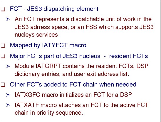
Function control table (FCT)
To decide which piece of work to do, JES3 maintains priority ordered chain of a function control table (FCT) entries. This chain serves as the JES3 “master dispatching queue”. The FCT is a chain of entries, each representing work to do in the form of a dynamic support program (DSP). What distinguishes DSPs from ordinary routines or subroutines is that DSPs are escheatable units. Before a DSP is executed, it must be scheduled by JES3. DSPs accomplish the pieces of work that JES3 performs.
The FCT chain elements are arranged according to the priority of the DSP, going from the highest to the lowest. Certain resident FCT entries that represent required DSPs have a higher priority than other FCT entries, however, priority is not related to residence.
The priority of an FCT entry is determined by the response requirements of the JES3 function involved. The last (lowest priority) FCT entry represents the WAIT DSP. When dispatched, the WAIT DSP issues an MVS WAIT macro indicating that JES3 has no more work to do.
Some FCT entries represent DSPs that perform required JES3 functions like operator communication and output services. These FCT entries are always present on the FCT chain. They are called resident FCT entries and they are not dynamically added or removed from the dispatching queue.
Non-resident FCT entries, on the other hand, are added (IATXATF) and deleted from the dispatching queue as needed. These non-resident FCT entries perform operator utility functions as well as other basic JES3 functions.
1.26 JES3 FCT dispatching
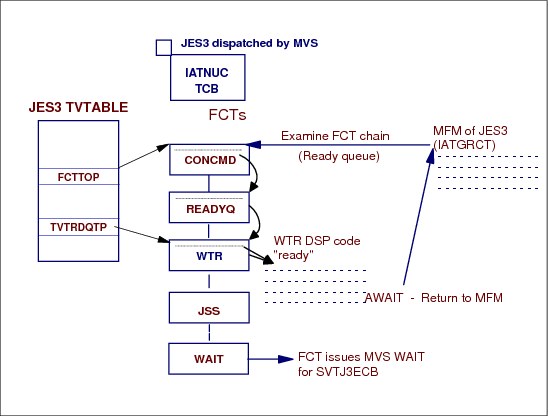
JES3 dispatched by MVS
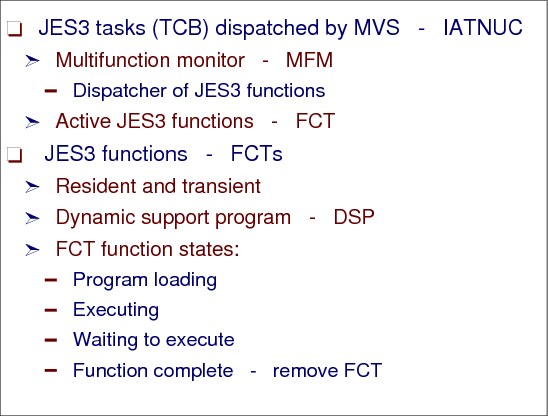
JES3 has its own address space in each of the mains in the complex. Each JES3 address space has identical functional capabilities, although each address space normally performs only a specific set of functions. The bulk of functions JES3 are performed under the JES3 nucleus task (IATNUC load module) in the global. The MVS dispatcher gives control to JES3 address space when it finds “ready” work (SRBs or TCBs) for the address space.
JES3 functions - FCTs
JES3 has a its own master dispatcher, called multifunction monitor (MFM), for JES3 functions under the nucleus task. The MFM, (module IATGRCT) controls which function of JES3 is to get control. The master dispatching queue for JES3 is called function control table (FCT). Entries in the FCT table are arranged in priority order and each represents one or more dynamic support program (DSP). A DSP is a JES3 program that implements a JES3 function. One or more DSPs may be executed for a single JES3 function.
The resident FCT table is build during JES3 initialization. The multifunction monitor selects the highest priority “ready” FCT entry from the table and transfer control to it.
Non-resident FCT entries, on the other hand, are added (IATXATF - attach FCT to active chain) and removed from the dispatching queue as they complete. These non-resident FCT entries perform operator utility functions as well as other basic JES3 functions. Each small piece of work that JES3 performs when processing a job is accomplished with a JES3 program called a dynamic support program, or DSPs. Each DSP is represented on the FCT chain by one or more FCT entries or elements. The elements on the FCT chain are executed according to their priority, and are placed on the FCT chain with the high priority elements first. The higher priority elements are executed before the lower priority elements.
JES3 function synchronization - AWAIT
The AWAIT macro allows a JES3 function to wait for the occurrence of one or more events.
The AWAIT macro refers to an one byte event completion flag (ECF) to synchronize processing. The macro supplies an ECF mask, which is compared to the ECF to determine when one or more of the events have occurred.
For the AWAIT TYPE=ON macro, completion is indicated when any corresponding ECF mask bit is on in the ECF.
For the AWAIT TYPE=OFF macro, completion is indicated when all bits specified in the ECF mask are off in the ECF.
When the AWAIT condition is completed, the waiting FCT becomes “ready” for MFM dispatching.
Normal JES3 DSP processing consists of short execution intervals between waits. For most DSPs, these breaks occur naturally. However, if a DSP runs a long time without giving up control, it should issue the AWAIT TYPE=ON macro specifying a posted ECF at regular intervals.
The AWAIT TYPE=ON macro specifies that control is to be returned to the function issuing the macro only when at least one of the specified events have occurred. By providing dummy AWAIT macros in which the events being waited for are already posted as complete, the DSP gives the multifunction monitor (MFM) control to let higher priority DSPs execute.
JES3 does not provide a “POST” macro. ECFs are posted by using machine instructions that manipulate the ECF byte bits.
1.27 FCT chaining

FCT chaining
The FCT chain is expanded or contracted as functions become active or terminate; thus, the FCT reflects the active components of the system at any given time. The first FCT in the chain is pointed to from the JES3 TVTABLE entry at label FCTTOP.
JES3 dispatches an FCT entry the same way as MVS dispatches a task control block (TCB). The FCT entry representing a DSP is one element on the FCT chain. The FCT chain elements are arranged according to the priority of the DSP, going from the highest to the lowest. Certain resident FCT entries that represent required DSPs have a higher priority than other FCT entries, however, priority is not related to residence.
The priority of an FCT entry is determined by the response requirements of the JES3 function involved. The last (lowest priority) FCT entry represents the WAIT DSP. When dispatched, the WAIT DSP issues an MVS WAIT macro indicating that there are no more dispatchable FCT entries on the FCT chain. In other words, JES3 has no more work to do.
READYQ FCT
To handle the ready queue, JES3 uses the READYQ FCT entry on the normal FCT chain. The READYQ FCT is assigned a high priority of 254. Whenever an FCT is added to the ready queue, the READYQ FCT is posted. When it encounters the posted READYQ FCT, the multifunction monitor scans the ready queue before it scans the normal FCT chain. (However, before scanning the FCT ready queue, the multifunction monitor scans for FCTs with priority 255.) JES3 places FCTs on the ready queue in "last-in-first-out" order. The priority of the FCTs on the ready queue does not matter (as it does on the normal FCT chain).
1.28 Resident FCT chain

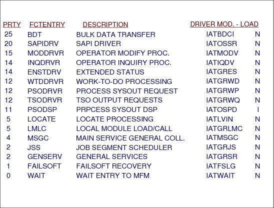
Resident FCTs
The visual shows the FCTs that are resident in the JES3 nucleus in module IATGRPT. There should be a minimum of 30 FCT entries in an active system. FCT entries are created for each active device in the system, printers and punches, both local and remote. Also consider the number of NJE and RJP lines active.
The next visual is a continuation of the resident FCT chain.
1.29 Resident FCT Chain
Resident FCTs continued
This visual is a continuation of the previous visual and shows the remainder of the resident FCTs which are available at the end of JES3 initialization.
1.30 FCT dispatching

FCT dispatching
When JES3 has built the FCT chain (which is an ongoing activity as more jobs are read into the system), JES3 begins to allow certain FCT entries to be dispatched for execution. The part of JES3 that handles this dispatching is the multifunction monitor (MFM). The multifunction monitor performs the following steps:
Scans the FCT chain for an FCT entry eligible for dispatching. Each scan begins at the top of the chain, with the highest-priority FCT entry. If no entries are ready for dispatching, the WAIT DSP is dispatched.
After processing the two console-related FCTs, the TIMER FCT, (and perhaps the DSI FCT) the multifunction monitor checks the READYQ FCT (representing the READYQ DSP). The visual shows the beginning of the normal FCT chain and the position of the READYQ FCT on the chain immediately following the two console-related FCTs and the TIMER FCT. If the READYQ FCT indicates the presence of FCTs on the ready queue, then the multifunction monitor examines the ready queue FCTs before resuming the scan of the normal FCT chain. JES3 builds the FCT ready queue in last-in-first-out order.
1.31 Example - MFM dispatch of WTR FCT
MFM dispatch of WTR FCT
When an DSP cannot proceed until one or more events have occurred, it issues an AWAIT macro. The macro parameters specify the completion conditions of an AWAIT (ON - any of the bits in the mask on; OFF - all of the bits in the mask off), the mask bits in the ECF to be tested, and whether a single ECF or a list of ECFs is used. An ECF is any byte in storage. JES3 does not have a formal POST macro. Any instruction that changes the bit settings of an ECF can be used for ECF posting.
To speed up the process of locating a “ready” FCT to be dispatched, JES3 uses a separate queue of FCTs (TVTRDQTP) from the normal FCT chain. This separate queue, called “FCT ready queue”, contains FCTs for JSAM I/O completion (AWRITE, WRTCHAIN, and JESREAD) that are posted and dispatchable. JES3 uses the READYQ FCT entry on the normal FCT chain to process the ready queue. When ever an FCT is added to the ready queue, the priority 254 READYQ FCT is posted. When the MFM encounters the READYQ FCT posted, it scans the ready queue before it scans the normal FCT chain. When all FCTs on the ready queue are processed, MFM starts again the FCT chain scan from the top (priority 255).
The multifunction monitor (MFM) performs the following steps:
1. Scans the FCT chain for an FCT entry eligible for dispatching. Each scan begins at the top of the chain, with the highest-priority FCT entry. If no entries are ready for dispatching, the WAIT DSP is dispatched. The priority of an FCT entry is determined by the response requirements of the JES3 function involved. The last (lowest priority) FCT entry represents the WAIT DSP. When dispatched, the WAIT DSP issues an MVS WAIT macro indicating that there are no more dispatchable FCT entries on the FCT chain. In other words, JES3 has no more work to do.
2. An FCT is eligible to get control if its AWAIT ECF is indicates completion. MFM tries to dispatches an FCT entry by branching to the first FCT in the chain. Each FCT contains code to test its Event Control Flag (ECF) and depending on whether or not the ECF is posted, the FCT branches to the next FCT in the chain (ECF not posted) or back into the MFM (ECF posted). At this point MFM determines if the "ready" FCT is the JES3 WAIT FCT, in which case MVS WAIT on master ECB is issued, otherwise the "ready-to-go" FCT is given control by restoring its register contents from the FCT and by branching to the address pointed by register 14.
1.32 JES3 TCB structure

JES3 TCB structure
The bulk of the JES3 processing executes under the IATNUC TCB. When the IATNUC TCB is given control by the MVS dispatcher, the process that had been interrupted resumes. If the JES3 “master” ECB (SVTJ3ECB - pointed also from ASPECB in TVT) was posted control is given to MFM. MFM gives control to the highest priority “ready” FCT. JES3 DSPs must not issue MVS WAITs. If DSPs require MVS services that explicitly or implicitly involve MVS WAITs, they must use generalized subtasks (IATGSC1) to execute the part of the program that involves MVS WAITs. The scheduling of work to all the other functional JES3 TCBs is done from the controlling DSPs running under the IATNUC task.
IATAUX task
The writer output multi-tasking (IATAUX) is used to offload a portion of the JES3 writer processing from the IATNUC task. At the point where a JES3 writer has selected a data set for printing, the writer may switch from the FCT under the IATNUC task to the auxiliary task. The writer output multi-tasking should be used when there is a large number of local and remote RJP printers. The writer output multi-tasking is not used for FSS writers. Writer output multi-tasking is optional and is specified through the JES3 initialization OPTIONS statement, as follows:
OPTIONS,MT= {ON|OFF}
Operators can control the auxiliary task through the commands:
*F MT= {ON|OFF} - Start or stop writer output multi-tasking
*I MT - Query the status of writer output multi-tasking
*I MT - Query the status of writer output multi-tasking
Other JES3 subtasks
IATMFTM This module is the JMF timer subtask which is attached when JMF is called and becomes active in the FCT chain. When IATMFTM gets control, it re-chains the JMF TCB above the JES3 nucleus task (IATNUC). Each time the STIMER cycle value expires, the IATMFTM sets the JES3 TCBs to be non-dispatchable. It then takes samples by calling the appropriate JMF modules and then resetting the JES3 TCBs to be dispatchable.
Operators can control the auxiliary task through the commands:
*CALL JMF - Invoke JES3 Monitoring Facility (JMF)
*CANCEL JMF - Cancel JMF
IATMDMT This module is responsible for attaching and detaching the MDS subtasks (IATMDST).
IATMDST This module is the MDS subtask used by MDS system verify and system select processing for the SSI calls to DFSMS/MVS. The number of tasks created is up to a maximum of 10. The numbers of tasks that are active is a function of the MDS processing workload for DFSMS managed data sets.
IATLVMT This module is the locate master task. It is responsible for attaching locate subtasks (IATLVLC). When an IATLVLC terminates (normally or abnormally), IATLVMT:
– Posts the DSP that was using the C/I subtask
– Posts the JES3 IATNUC task.
IATLVLC This module is the JES3 locate subtask. It is attached by the IATLVMT and posted by the locate FCT driver, IATLVIN, when there is work to do. Locate function is used by DSPs to obtain data set catalog information. Locate processing is performed on the JES3 global, JES3 local or in a C/I FSS address space.
IATGSC1 This module for the generalized subtasks are used by JES3 functions, DSPs, for calls that have implied MVS WAITs thus avoiding a wait of the IATNUC task. The maximum number of non-specific generalized subtasks is eight and specific is six.
IATIISB This module is the master task for all of the converter/interpreter (C/I) subtasks. It is responsible for attaching and detaching the C/I daughter tasks (IATIIST). When an IATIIST terminates (normally or abnormally), IATIISB:
– Posts the DSP that was using the C/I subtask
– Posts the JES3 IATNUC task.
IATIIST This module is used to drive the MVS C/I processing. The number of IATIIST TCBs is controlled by the CICNT parameter on the STANDARDS initialization statement. Operator may modify the subtask count through the command:
*F X,D=CI,MC=nn
IATSNLS This module consists of a subtask, which initiates the SNA RJP VTAM® communication, and VTAM exit routines. VTAM communicate with SNA RJP routines through VTAM exits, which are scheduled as IRBs running under the subtask.
IATGRSS This module is the general security subtask. It allow FCTs to asynchronously perform security checks without the AWAIT that is incurred while using a generalized subtask
IATGRMON This module is a subtask to monitor the active FCTs for the JES3 Nuc and Aux task.
1.33 Posting JES3 IATNUC ECB

Posting JES3 master ECB
The IATNUC TCB is posted by functions that are running asynchronously or initiated outside the JES3 address space, for example: JES3 I/O completion, timer pop, or staging area arrival. Each time the IATNUC TCB is posted, the ECF of the individual JES3 function (FCT) that processes the completed event is also posted. These ECFs have their addresses normally in the SSVT, DSQ or TVT control blocks. The IATNUC TCB is posted by obtaining the address of the IATNUC ECB and issuing an MVS POST macro.
Once the IATNUC TCB is posted, the task can be dispatched by the MVS dispatcher. Therefore, there is a percentage of time that the IATNUC TCB may be posted but not active while higher priority address spaces are dispatched.
JES3 DSPs must not issue MVS WAITs. If DSPs require MVS services that explicitly or implicitly involve MVS WAITs, they must use generalized subtasks (IATGSC1) to execute the part of the program that involves MVS WAITs.
1.34 Major JES3 control blocks
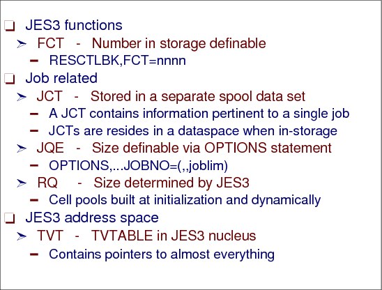
Function control table (FCT)
The FCT is a chain of entries, each representing work to do in the form of a DSP. Every DSP corresponds to one or more entries on the FCT chain. The FCT entry holds DSP status, DSP priority, the status of resources needed by the job, and other job information.
You should use the resident control block (RESCTLBK) initialization statement to preallocate storage for the highly used JES3 FCT entries: RESCTLBK,FCT=nnn. Using high enough RESCTLBK FCT count can reduce GETMAIN overhead and the associated paging overhead.
Job queue element (JQE)
JQE is a control block containing summary information a job description (JCT). JQEs are storage resident and are used by JES3 instead of JCTs when scheduling work.
The size of the JQE tables are determined by the number of jobs allowed in the system and the range of job numbers as defined on the OPTIONS initialization statement.
OPTIONS,.,JOBNO=(lowest,highest,joblim)
Resqueue element (RQ)
Resident queue (RQ) is a storage resident control block that is created by the job segment scheduler (JSS) to represent current JES3 processing step (scheduler element) of jobs. It contains status information and queue pointers. a particular DSP.
An RQ consists of a fixed section (common to all functions), plus a function dependent variable section. There are five variable sections:
•OUTSERV variable section - contains data used by output service
•MDS variable section - contains data used by MDS for SETUP processing. The MDS variable section starts after the OUTSERV variable section.
•GMS variable section - contains data used by GMS after MDS SETUP is complete. The GMS variable section starts after the MDS variable section.
•CI variable section - contains data used by the CI and postscan DSPs. The CI variable section starts after the GMS variable section.
•Common variable section - contains data used by all other functions. The common variable section starts after the CI variable section.
Scheduler element
A scheduler element is a part of the JCT entry and represents one or more DSPs needed for JES3 processing of a job. A scheduler element defines a piece of work for JES3 to do. Job segment scheduler (JSS) is a DSP that scans the JCT table to locate scheduler elements eligible for processing, and then builds RQ and FCT entries so that the corresponding DSPs can be dispatched. JSS DSP itself is running under its own FCT.)
There are no external means to influence the size or number of extents in each RQ cell pool.
Job control table (JCT)
One of JES3 job's control blocks, the JCT entry, resides in storage until JES3 writes it into a unique data set on DASD and in a data space. This data set is called the JCT data set and it contains JCT entries for all jobs currently known to JES3. The data set is defined in the JES3 JCL procedure and is allocated during the JES3 address space initialization. The JCT data set does not reside within the DASD space allocated for spool. The JCT entries describe the jobs to be processed by JES3 and for each job the scheduler elements representing the DSPs required to process the job.
Transfer vector table (TVT)
Two control blocks, the subsystem vector table (SSVT) and the transfer vector table (TVT), anchor all the data areas and service routines required for JES3 processing. They exist in storage in two distinct areas; SSVT in MVS common storage (CSA below the line) and TVT in JES3 address space’s private area.
The JES3 private address space contains the control blocks for all global, local or C/I FSS data used for DSP executions. This data is accessed through the TVT. Most JES3 global services are accessed through the TVT. It includes the following information:
•The addresses of most of the control blocks in the JES3 private address space.
•The entry point addresses of most of the JES3 services (resident code).
•Status information for all JES3 functions.
1.35 JES3 DSP dictionary
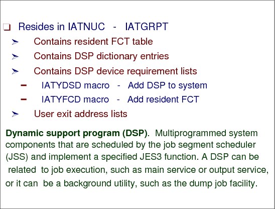
JES3 DSP dictionary
The DSP dictionary provides information about all DSPs that can become active in the JES3 system. Such information is required to dynamically build non-resident FCTs.
The IATYDSD macro generates an entry for a dynamic support program (DSP) in the DSP dictionary (module IATGRPT or, in a C/I FSS address space, module IATGRPTF). An entry in the table is required for each DSP in order for it to be recognized as part of JES3. The IATYFCD macro generates the permanent function control table (FCT) entries in the DSP dictionary for JES3 functions such as: console service and the main device scheduler (MDS).
Dynamic support program (DSP)
A dynamic support programs are multiprogrammed system components that are scheduled by the job segment scheduler (JSS) and implement a JES3 function. A DSP can be related to job execution, such as main service or output service, or it can be a background utility, such as the dump job facility.
Job segment scheduler (JSS)
A dynamic support program (DSP) that selects scheduler elements that are ready for processing and then builds corresponding entries in the function control table (FCT).
Scheduler element
Scheduler element is the part of the job control table (JCT) entry that represents one or more dynamic support programs (DSPs) needed for processing of jobs by JES3.
1.36 JCT control block

Job control table (JCT) control block
The JES3 job is defined by means of a spool resident control block called a job control table (JCT) entry. The JCT also serves as a continually-updated checkpoint of the status of the job as it progresses through the system. A job exists in the system when it JCT entry is created and ceases to exist when the JCT entry is removed. The JCT entry is part of a major JES3 control block called the job control table (JCT) which is a data set on a DASD device. The name of the data set is JES3JCT. You define the JCT data set during JES3 initialization.
The JCT data set contains a record for every job in the JES3 complex. Many JES3 functions, such as inquiry and modify, access the JCT. The job segment scheduler (JSS) is the JES3 function that accesses and updates the JCT most frequently.
Each JCT entry contains information about the job and an entry for each SE. Each SE entry contains flags indicating that SE's status: inactive, active, or complete. JSS uses these flags to determine which SE is next for scheduling/ending function: the first SE that is not marked complete is selected, and is marked either complete or active, for either ending function or scheduling. The JCT also serves as a continually-updated checkpoint of the status of the job as it progresses through the system. A job exists in the system when its JCT entry is created and ceases to exist when the JCT entry is removed. The entry contains:
•The job name
•The job number
•The job status
•A number of SEs (one for each piece of work to be performed on behalf of the job)
•Spool addresses of other job-related control blocks
1.37 Job queue element - JQE

Job queue element (JQE) control block
IATGRJX module services the IATXJCT and IATXJQE macro requests. These macros are used to access the JCT and JQE structure respectively.
A JQE is a control block containing a summary of information from a job control table (JCT) entry. JQEs move from queue to queue as work moves through each stage of JES3 processing.
When a job enters the system, JES3 assigns a job number and a JQE to it. When the JQE is assigned, it is added to the appropriate priority chain anchored in the JCT access method data area (JQX), based on the priority specified in the job's JCL.
Once a JQE is associated with a job, that JQE is always on a priority chain (although it may not always be on the same priority chain). The job scheduler (JSS) searches these priority chains for scheduler elements (SEs) ready for scheduling.
1.38 JQE table

Job queue element (JQE) table
The job queue element (JQE), another JSS-related control block, is also closely related to a job (JCT) but is kept in storage. The JQE contains almost all the data critical to JSS processing decisions and exists to reduce the I/O activity that would result from frequent examination of JCT entries for the scheduling of work. It is a highly abbreviated collection of information about the job, mostly copied from the job's JCT entry. It contains only that information needed to make scheduling decisions and maintain in-storage job status.
It is the JQE that is first examined by the job segment scheduler when it searches for work to be done. The JQE is also used to answer most system or operator inquiries about jobs, further removing a need for JCT access. JQEs are constructed during JES3 initialization and allocated for a job when its JCT entry is added to the job queue. The JQE structure includes five control blocks imbedded in one data area. JQE0, JQE1, JQE2, and JQE3 contain information to manage JQE4.
JQE0 JQE0 is a table for managing the virtual storage in which the entire JQE structure resides.
JQE1 JQE1 is the allocation table. Each bit corresponds to an entry in the jqe3 and JQE4 tables. There is one bit per job number. When a JQE needs to be allocated the bit map is searched for the first unused entry. The JQE3 and JQE4 that correspond to this entry are then used for the job.
JQE2 JQE2 is the job number table. There is a halfword for each possible job number. That is, the first JQE2 corresponds to the first job number, the second JQE2 to the second job number etc. The JQE2 contains the index (relative JQE
number) into the JQE3 and JQE4 tables of the entries that correspond to that job number.
JQE3 JQE3 is a jobname/userid table. There is an 16 byte entry for each job name in the system. The JQE3 is allocated using the JQE1 table.
JQE4 JQE4 contains the summary information from the JCT entry it is associated with. The number of JQE4 slots equals the maximum number of jobs that can be in the job queue at any given time. The JCT/JQE access method routine in IATGRJX updates JQE4.
The JQE tables are obtained (using the AGETMAIN macro) in contiguous storage during JES3 initialization. The JQE4 table, which is mapped by IATYJQE, contains an entry for each job. The job number range is defined in the initialization stream. Each JQE4 entry contains a subset of the information contained in the JCT for that job. The JQE4 entries also appear on many queues used by JSS for scheduling decisions, and therefore also contain chaining fields in addition to job information.
1.39 RESQUEUE control block - RQ
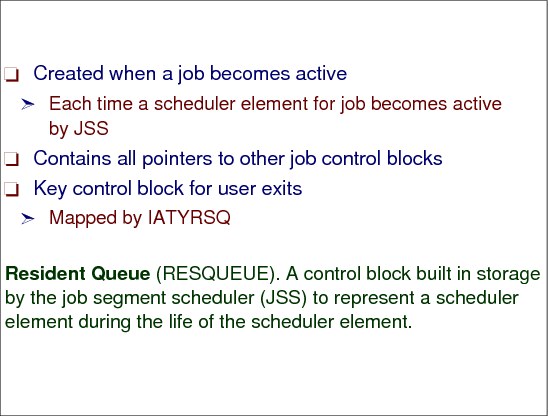
RESQUEUE control block
The job scheduler (JSS) creates a new RQ each time it schedules a phase (SE) of a job; the RQ lasts only as long as the SE. Therefore, during its life, one job will have many RQs, as the JSS proceeds to schedule its SEs. A RQ entry may be concurrently used by many JES3 functions. This is accomplished by a series of chaining fields in each entry. However, each function has only one chaining field. All RQ entries are chained from the transfer vector table (TVT). The RQ is chained from the FCT when one FCT is responsible for processing a single job. The RQ entry has pointers to all of the job's control blocks making it an important control block for user exits.
1.40 RESQUEUE types and sections

RESQUEUE types and sections
Because many functions must concurrently access information in the job queue, some JCT entry information resides in main storage. This resident portion is called the resident job queue element (RQ). This control block is built by the job segment scheduler to represent an SE during its processing. It lasts only for the life of an SE. Each RQ contains pointers to the primary control blocks of a job on spool (JDAB, JST, JMR, JOBTAT, JDS, and OSE).
When the job segment scheduler is dispatched, it examines JQEs to find an eligible job so it can schedule a DSP. Part of this processing is construction of an FCT entry when the DSP being scheduled is not represented by a resident FCT entry. In addition to constructing and enqueuing an FCT entry (if necessary), the job segment scheduler always builds a resident job queue element. Spool addresses from the JCT entry to the job's other single-record files (SRFs) are extracted and placed into the RQ, which also contain status flags, job information fields, and queueing pointers.
1.41 RQ control blocks

RQ control block types
The RESQUEUE control block consists of 6 different sections. This change to the structure of the RESQUEUE is for storage constraint. The six different sections are:
Fixed This area contains data common to all functions and exists in every entry. It primarily contains data from the JCT.
OUTSERV This section contains data used by output processing and always follow the fixed section for every RESQUEUE type.
MDS This section contains data related to setup processing. It exists in the RESQUEUE entry following the output section and is present under the MAIN and CI scheduler elements.
GMS This section exists only under the CI scheduler element. It follows the MDS section in the entry.
CI This section exists only under the CI scheduler element. It follows the MDS section in the entry.
Common This section exists for all scheduler elements other than the CI, MAIN, and OUTSERV. It follows an OUTSERV entry in the entry.
1.42 JES3 naming conventions

JES3 naming conventions
Most JES3 module names are seven characters long and begin with the characters IAT. The fourth and fifth characters are a mnemonic that represents a specific function. The sixth and seventh characters indicate a service performed by that module within the function. For example IATISDV:
•IAT signifies that this is a JES3 module.
•IS signifies that this is an input service module.
•DV signifies that this is the device driver module.
The mnemonic in the fourth and fifth character indicates any of the following module functions:
AB - abnormal termination
BD - MVS/Bulk Data Transfer
CN - console services
BD - MVS/Bulk Data Transfer
CN - console services
CS - callable services
DC - dependent job control
DJ - dump job
DL - deadline scheduling
DM - spool data management
DS - dynamic system interchange
DY - dynamic allocation fastpath
FC/FP - functional subsystem interface
FS - failsoft
GR - general routines
GS - generalized subtask service
II - converter/interpreter service
IN - initialization
IP - interactive problem control system
IQ - operator inquiry commands
IS - input service
JV - job validation
LV - locate/verify
MD - main device scheduler
MF - JES3 monitoring facility (JMF)
MO - operator modify commands
MS - main service and generalized main scheduling
NT - JES3 networking
OD - output service data
OF - initialization offset table
OS - output service
PU - purge
RJ - binary synchronous communication remote job processing
SN - systems network architecture remote job processing
SS/SI - subsystem interface
UT - operator utilities
UX - user exit
OS - output service
PU - purge
RJ - binary synchronous communication remote job processing
SN - systems network architecture remote job processing
SS/SI - subsystem interface
UT - operator utilities
UX - user exit
The sixth and seventh characters restrict any of the above mnemonics to further classification of a specific task, and indicate (but are not limited to) any of the following:
XM - cross memory processing
DV or DR - driver module for a particular DSP
DT or DA - data CSECT for a particular DSP
CR - card reader processing
MN - monitor
DV or DR - driver module for a particular DSP
DT or DA - data CSECT for a particular DSP
CR - card reader processing
MN - monitor
Due to the limited number of combinations provided by 2 characters, there are exceptions to these conventions.
Additional conventions are:
•The fourth character of most JES3 executable macros is an X (but there are executable macros that do not follow this convention):
IATX__ __ __
•The fourth character of a JES3 data area mapping macro is a Y:
IATY__ __ __
•The fourth character of a JES3 macro that expands within other JES3 macros is a Z:
IATZ__ __ __
The JES3 nucleus load modules are named:
IATNUC - JES3 address space
IATNUCF - C/I FSS address space
IATNUCI - Initialization stream checker
IATNUCF - C/I FSS address space
IATNUCI - Initialization stream checker
..................Content has been hidden....................
You can't read the all page of ebook, please click here login for view all page.