

Converter/interpreter processing
The JES3 converter/interpreter (C/I) service controls the conversion of JCL statements to converter/interpreter text and then into SWA control blocks. This service comprises primarily the JES3 CI and POSTSCAN dynamic support programs, the C/I subtasks under which the MVS C/I routines run, and the initiator support routines.
The Converter/Interpreter processing of a job control language (JCL) statement includes the stage of converting the JCL statement to converter / interpreter (C/I) text, a form of data that the job entry subsystem (JES) and the job scheduler function of MVS both recognize. The converter takes the job's JCL, merges it with JCL from a procedure library, and converts the composite JCL into C/I text. The converter scans each JCL statement for syntax errors and issues appropriate error messages. The converter also resolves symbolic parameters and assigns default values. The C/I text is further interpreted to build the necessary control blocks needed before the job can be scheduled for execution. The output of the interpretation is stored the scheduler work area (SWA).
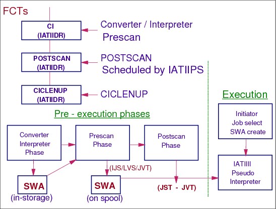
The three JES3 principal phases of C/I service are:
•Converter/Interpreter phase: Uses the MVS C/I routines to convert and interpret JCL into scheduler control blocks. At this time, the scheduler control blocks are created in the scheduler work area (SWA).
•Prescan phase: Extracts job requirements from the scheduler control blocks for use in the postscan phase. At the end of the prescan phase, the scheduler control blocks are moved from the SWA to JES3 spool.
•Postscan phase: Locates data sets and gathers information for use in JES3 device setup.
7.1 Job active at CI scheduler element
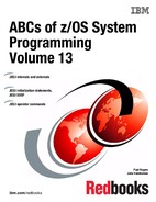
Job active at CI scheduler element
When JES3 has a job that can be scheduled for C/I processing, it determines whether a CI DSP in the JES3 global address space or a C/I FSS address space is available for the job. You can select the main where the job will be scheduled for C/I service as well as whether the job is eligible for C/I processing in the JES3 global address space by implementing installation exit IATUX46 (Select Processors Eligible for C/I Processing). If the initialization stream defines C/I FSS address spaces, you can override JES3's selection of an address space by implementing installation exit IATUX49 (Override the Address Space Selected for C/I Processing). JES3 schedules the job to an available CI DSP based on the installation exit routines' responses.
JSS scheduling of CI
JES3's decision as to where to schedule C/I processing are also influenced by the CIDEMAND (for demand select jobs) and CIBATCH (for batch jobs) initialization parameters on the CLASS and/or STANDARDS initialization statements. These parameters indicate that jobs of a certain class or all jobs may have C/I processing performed only where the job's class is enabled or where the job is eligible to run.
Exit IATUX46
When JSS is ready to schedule a job for converter/interpreter, C/I) processing it calls the converter/interpreter (C/I) scheduling module IATIICS as a subroutine. IATIICS calls the select processors eligible for C/I processing exit IATUX46 when C/I FSS address spaces are defined. Exit IATUX46 allows to override JES3's decision and provide your own list of mains that are eligible to do the converter/interpreter, prescan, and locate phases of a job's C/I processing.
If your installation does not define any C/I FSS address spaces, JES3 marks exit IATUX46 routine as a dummy at initialization and never calls it, because without any C/I FSSs, all C/I processing will occur on the global main.
The converter/interpreter (C/I) scheduling module IATIICS calls t exit IATUX49 routine after an address space has been selected for a job's C/I processing. IATUX49 can accept or reject the address space selected. If the CI address space selection is accepted, a RESQUEUE and a CI FCT are initialized and attached to the proper chains. The job is now under the control of a CI/POSTSCAN/CICLENUP DSP driver module IATIIDR.
(JES3 C/I subtask (IATIIST) calls installation exit routine IATUX41 (Determine the Disposition of a Job that Exceeds the Job JCL Limit) if the number of JCL statements in a job exceeds the job JCL statement limit -- MAXJOBST parameter on the STANDARDS statement. If so, exit IATUX41 can allow JES3 to continue processing. Otherwise JES3 cancels the job from the system with print.)
CLASS initialization statement
The CLASS initialization statement defines the characteristics of JES3 job classes which include:
•CIBATCH= indicates whether or not batch jobs of this class must have CI processing limited to certain processors. If specified for a class, this will override the value specified on the CIBATCH parameter on the STANDARDS statement. If not specified, JES3 will use the value specified on or defaulted to on the STANDARDS statement.
– JOB - indicates CI processing must be performed on a system on which the job is eligible to run.
|
Note: Only the JES3 //*MAIN SYSTEM= JECL statement (NOT the job's scheduling environment) is considered for CI scheduling purposes when determining where the job is eligible to run.
|
– CLASS - indicates CI processing must be performed on a system on which the job's JOB CLASS is enabled.
– ANY - indicates CI processing may be performed on any processor regardless of job or class eligibility.
•CIDEMAND= indicates whether or not demand select jobs of this class must have CI processing limited to certain processors. If specified for a class, this will override the value specified on the CIDEMAND parameter on the STANDARDS statement. If not specified, JES3 will use the value specified on or defaulted to on the STANDARDS statement.
•JOB - indicates CI processing must be performed on a system on which the job is eligible to run.
•CLASS - indicates CI processing must be performed on a system on which the job's JOB CLASS is enabled.
•ANY - indicates CI processing may be performed on any processor regardless of job or class eligibility.
STANDARDS initialization statement
The STANDARDS initialization statement to specify default values for information not provided on other JES3 initialization statements. The CIBATCH= and CIDEMAND= parameter definitions are the same as on the CLASS statement.
7.2 Interpreter service
Interpreter service
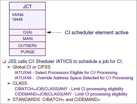
The converter/interpreter (C/I) is the first scheduler element for every standard job. During C/I processing, the JCL is converted into scheduler work area (SWA). The SWA is stored on the JES3 spool. The JES3 CI process extracts jobs’ I/O resource requirements from the SWA control blocks if pre-execution setup is to occur. C/I routines provide input to the main device scheduling (MDS) routines by determining jobs’ devices, volumes, and data sets requirements.
Prescan phase
The primary function of the prescan phase is to extract each job's resource requirements from the SWA control blocks created in the interpreter phase. On entry to the prescan phase, JES3 examines the SETUP parameter on the JES3 STANDARDS initialization statement:
•If you specify SETUP=NONE (that is, you do not want JES3 to perform pre-execution setup for the complex), JES3 does not build extract resource requirements.
•If you specify any value other that NONE on the SETUP= keyword, JES3 determines the job's resource requirements.
Installation exits IATUX04 (Examine the Job Information), IATUX05 (Examine the Step Information), and IATUX06 (Examine the DD Statement Information) allow you to examine or change job, step, and DD information, respectively. You can use these exits to examine or change the information before processing begins.
If the job is being processed in a C/I FSS, JES3 determines whether the job is eligible to have catalog searches performed on the main where the C/I FSS is executing. If catalog searches can be performed on that main, locate processing occurs in the C/I FSS and control then returns to the JES3 global address space for the remainder of postscan processing.
Postscan phase
The functions of the postscan phase are to resolve cataloged data set references and prepare the job for the main device scheduler (MDS).
Cataloged data set resolution
If SMS is active, JES3 calls it to search the system catalogs and collect scheduling information for the job. SMS searches the system catalogs to obtain information about a job's data sets when the job's JCL does not specify unit information.
If SMS fails to find a data set name, the postscan phase calls installation exit IATUX07 (Examine/Substitute Unit Type and Volume Serial Information). Through this installation exit, you can examine the available data set information and, if necessary, supply the unit and volume information.
If a data set has been migrated (or is eligible to be migrated) by the Hierarchical Storage Manager (HSM), the LOCATE request for that data set causes JES3 to associate the data set with a set of volumes to which it can be recalled. HSM limits the choice of volumes eligible for recall during LOCATE processing in accordance with its space management algorithms. JES3 processing continues as though the data set is recalled to all eligible volumes. However, the actual recall does not occur until job execution when MVS issues a LOCATE request. At that time, HSM determines which volume is the best choice to recall the data set to and then recalls the data set to that volume. HSM derives an SMS storage class and an SMS storage group for SMS-managed data sets.
In addition, whenever the response of a LOCATE request has been received, you can use installation exit routine IATUX11 (Inhibit Printing of the LOCATE Request/Response) to inhibit printing of the LOCATE request/response in the JESYSMSG data set.
JST and JVT
The JST(IATYJST mapping) control block describes a job’s unit, volume, and data set requirements. The JVT (IATYJVT mapping) contains lists of volumes and is used to pre-allocate volumes for a job. The JVT used with the JST. Each JVT entry is associated with a JST entry. The first JVT entry associated with a JST entry is copied into the JST entry.
High watermark setup (HWS)
High watermark setup, as defined on the HWSNAME initialization statement, reduces the number of devices JES3 reserves for a job. To determine how many devices of a particular type to reserve for a job, JES3 considers the needs of each of the job's steps. In this way, JES3 determines which step needs the greatest number of devices of that type; JES3 then reserves that many devices of that type for the job. JES3 repeats this process for each device type the job needs. As a result, high watermark setup can cause premounting of all mountable volumes. Volume unloading and remounting may occur for both private and public volumes, even when RETAIN® has been specified on the applicable DD statement.
7.3 Interpreter parameters

Interpreter parameters
The CIPARM initialization statement specifies the options to be used by the MVS converter/interpreter (C/I). These options are used as system defaults applied to certain JCL statement parameters and other options for jobs scheduled on any main.
The default CIPARM is:
CIPARM,PARM=(00000300025631E00011A),PARMID=01,AUTH=ALL,COMMAND=IGNORE
PARMID parameter
Specifies a 2-byte identifier associated with this option list. This parameter provides the facility to have a variety of C/I option lists. The operator may select the option list to be used by specifying the identifier on the *CALL, CR, DR, or TR command.
Specify the PARMID parameter to distinguish option lists if you include more than one CIPARM statement in the initialization stream.
PARM parameter
The PARM parameter defines a 21-character parameter string that the MVS Converter/Interpreter uses when processing jobs. The parameter string format: bppmmmmsscccrlaaaaefh
b An account number or programmer name is required
pp Default job priority. This field is ignored by JES3
mmmmss Maximum length of time each job step may execute
ccc Job-step region default
l Processing options for BLP parameter of the DD statements
e MSGLEVEL default
f Allocation MSGLEVEL default
h MSGCLASS default
Two fields have a fixed value always set by JES3: positions 13 (r) and 15-18 (aaaa).
AUTH parameter
The AUTH parameter specifies which commands will be accepted through COMMAND JCL statements in the job stream. The groups includes:
•SYS -- system commands
•IO -- input/output commands
•CONS -- console commands
•INFO -- information commands (such as display)
•ALL -- all operator command types.
COMMAND parameter
The COMMAND parameter specifies the disposition of commands entered through COMMAND JCL statements in the job stream as follows:
•DISPLAY -- The command is displayed and scheduled for execution.
•EXECUTE -- The command is scheduled for execution.
•IGNORE -- The command is ignored (that is, interpreted as a “no operation”). IGNORE is the default.
•VERIFY -- Specifies that the system displays the command, asks the operator whether the command should be executed, and if the operator replies “YES”, schedules the command for execution.
REGION parameter
The REGION parameter specifies the job-step region default size.
•nnnn -- specifies the 1- to 4-digit number of units used for the default region size for a job step. This value overrides the region size in the PARM option list, and is otherwise processed the same way. If you do not specify this parameter, JES3 obtains the region size from the PARM option list.
•x -- Indicates the unit of measure as kilobytes (K) or megabytes (M)
– For nnnnK, the maximum allowable value is 9999K
– For nnnnM, the maximum allowable value is 2047K.
PRTY parameter on STANDARD statement
The PRTY parameter on the STANDARDS statement overrides any value specified in columns two and three (pp) of the option list.
7.4 C/I parameters and managing proclibs
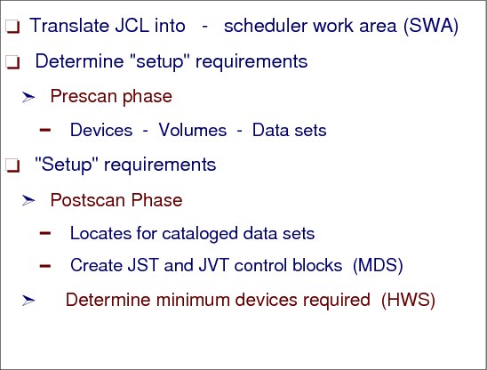
C/I parameters -- operator called reader jobs
The PARMID= specifies a 2-byte identifier associated with an CIPARM option list. This parameter provides the facility to have a variety of C/I option lists. The operator may select the option list to be used by specifying the identifier on the DR or CR command.
To define and name an options list, code a CIPARM initialization statement. Use the PARMID= parameter on this statement to name the list. You must code a separate CIPARM statement for each options list.
Each time the operator calls a disk reader, a card reader, or a tape reader, the operator can select one of the options lists that you defined. Thereafter, each time the MVS C/I routines process a job read from that particular reader, the MVS C/I routines use the selected options list.
C/I parameters - internal reader jobs, started tasks, and TSO logons
To specify which options list the MVS C/I routines should use for internal reader jobs, started tasks, and TSO LOGON jobs, use the INTPMID, STCPMID, and TSOPMID parameters on the STANDARDS initialization statement.
The INTPMID= parameter on the STANDARDS statement specifies the 2-byte identifier (ID) of the converter/interpreter options list for jobs entered using the internal reader. The ID must match the ID specified by the PARMID parameter on a CIPARM initialization statement. If no CIPARM statements are included in the initialization stream, the default value is used.
User exit IATUX29
IATUX29 exit is entered at the completion of input service processing. Module IATISEN provides access to the job control table (JCT), job description accounting block (JDAB), and job management record (JMR) for the job. This exit could be used to move the accounting information to the SMF record. You can examine and modify the job accounting information in the JDAB, the CIPARM list ID (JDABPMID), the procedure library ID (JDABPROC), and output limits an output options for jobs that are started tasks.
PROCLIBs
During the CI processing the converter takes the job's JCL, merges it with JCL from a procedure library, and converts the composite JCL into C/I text.
The procedure library concatenations JES3 passes to the MVS converter are defined on the STANDARDS initialization statement:
•The INTPROC parameter specifies the appropriate IATPLBxx procedure library to be searched by the MVS converter when resolving procedure references for jobs submitted using the internal reader.
|
Note: Jobs entering from a disk reader or NJERDR use the standard procedure library as defined on the IATPLBST.
|
•The STCPROC parameter specifies the appropriate IATPLBxx procedure library used for started task jobs.
•The TSOPROC parameter specifies the appropriate IATPLBxx procedure library to be used for TSO LOGON jobs.
All procedure libraries must be defined by an IATPLBxx DD statement in the JES3 start procedure or by a DYNALLOC initialization statement.
An individual job can override the procedure library ID using the PROC parameter on the //*MAIN JES3 control statement:
•PROC=xx names the procedure library that the system is to search for cataloged procedures called by EXEC statements in the job. If a procedure cannot be found in the named library, JES3 abnormally terminates the job.
If this parameter is omitted, the default depends on the source of the job. If the job is submitted as a batch job, the default is ST. If the job is submitted from an internal reader, the default can be another procedure library, as specified by the installation on the STANDARDS initialization statement (the INTPROC, STCPROC, or TSOPROC parameters).
|
Note: Converter/Interpreter functional subsystems (C/I FSS) and the PROCLIB update function will obtain unit and volume information for the procedure libraries from the catalog. For these functions, JES3 ignores unit and volume information that you specify in the JES3 start-up procedure or on a DYNALLOC initialization statement.
|
7.5 CI initialization definitions
CI initialization definitions
During JES3 initialization, JES3 attaches an installation-defined number of converter/interpreter (C/I) tasks. The C/I tasks are subtasks to the JES3 nucleus task. When a C/I subtask processes a job, the scheduler work area (SWA) in the address space in which the service is invoked (global or functional subsystem) provides temporary storage for the job's converted JCL statements. The SWA storage remains allocated until the C/I subtask finishes processing the job. When several C/I subtasks run concurrently, the SWAs of all the jobs are in-storage simultaneously. The initially by a C/I subtask created SWA is always located above 16-megabytes.
CI subtasks
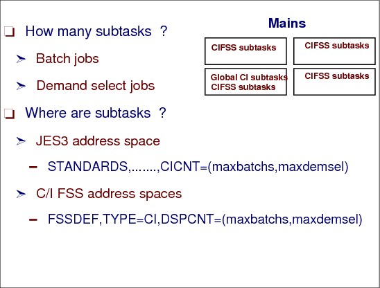
The STANDARDS statement CICNT parameter specifies the maximum number of CI DSPs that can operate in the JES3 global address space at any time. The first subparameter (maxbatch) specifies the maximum number of CI DSPs that process batch jobs. The second subparameter (maxdemsel) specifies the maximum number of CI DSPs that process demand select jobs (that is, started tasks and TSO LOGONs). The sum of the two subparameters cannot exceed 255. CI DSPs defined to process batch jobs cannot be used to process demand select jobs, and vice versa.
CIFSS subtasks
The CI DSPs execute in the JES3 global address space. The characteristics of C/I FSS functional subsystems, which operates in their own address spaces, are defined with the FSSDEF,TYPE=CI statement. DSPCNT parameter specifies the maximum number of CI DSPs that can operate in the C/I FSS address space at any time.
CI scheduling rules
When a job is ready for converter/interpreter service (represented by the C/I scheduler element) the job segment scheduler (module IATGRJS) calls IATIICS (using the IATXSCH macro) to schedule the job for C/I. JSS does the following in selecting where to run CI:
1. First, IATIICS checks for an available CI DSP first in the JES3 global address space. If C/I FSSs were defined at initialization, IATIICS scans the C/I FSS tables to see if any available CI DSPs are in any of the C/I FSS address spaces. It then sets up a main mask to indicate which main processors have C/I FSSs with available CI DSPs. If no CI DSPs are available, IATIICS checks to see if the job is a demand select job used to start a C/I FSS address space. If so, the job is scheduled to use the C/I subtask reserved for starting C/I FSS address spaces. Otherwise, IATIICS returns to JSS (IATGRJS) indicating that no CI DSP is available. JSS will try again when a CI DSP is available.
2. IATIICS searches the main processor control tables (MPCs) to see if there are any eligible processors for locate processing. Locate processing is done only on mains that are eligible to run the job and only those mains that are connected and on-line. If no mains are available, IATIICS returns to JSS, indicating that no main processor is available. (JSS will try again when a processor is available.)
3. If the job uses a procedure library, IATIICS searches the procedure library tables to find the procedure library that the job uses. If the procedure library is being updated or is disabled IATIICS returns the job to JSS, indicating that no procedure library was available. (JSS will try again when a processor is available.)
4. If all the above conditions are met and C/I FSSs are defined, IATIICS calls user exit IATUX46. IATUX46 selects the eligible processors for C/I (using the main mask set up earlier), and indicates whether the job can be scheduled for C/I in the JES3 global address space. (IATIICS does not call IATUX46 if it is a dummy exit or if the special demand select job that starts a C/I FSS address space is being scheduled.)
5. If the user exit eliminates all possible choices for CI, IATIICS returns to JSS, indicating the user exit rejected the job. If the main mask was modified by IATUX46, IATIICS searches the C/I FSS tables to eliminate as scheduling choices, any FSSs not included in the main mask.
6. Once an address space is selected, IATIICS calls user exit IATUX49. IATUX49 accepts or rejects the address space selected for a given job. (IATIICS does not call IATUX49 if it is a dummy exit or if the job reserved for starting C/I FSS address spaces is scheduled to use the C/I subtask.)
7. If IATUX49 accepts the choice, IATIICS does processing based on the address space selected, JES3 global or C/I FSS. If the JES3 global was selected, IATIICS initializes a RESQUEUE and a CI FCT and puts them on the proper chains.
If a C/I FSS is selected, IATIICS initializes the RESQUEUE, locks the control block FDBs in the RESQUEUE (used in the C/I FSS address space) so that they cannot be updated while they are in the FSS address space. IATIICS places the FSID into the job's JCT (to identify where the job is, should there be a JES3 restart), and sends the job to the FSS address space by issuing the IATXCIO macro.
8. If the job cannot be scheduled for converter/interpreter service, (for example, all FSSs terminated or user exit IATUX49 rejected all choices) IATIICS cleans up and returns control to the job segment scheduler.
|
Note: In order for CI to be scheduled on a main processor, the main processor must not have been previously ruled out due to the CIBATCH or CIDEMAND parameter.
|
7.6 Where does CI processing take place

CI scheduling
CIBATCH= indicates whether batch jobs must have CI processing limited to certain processors. This will apply to all batch jobs unless overridden by the CIBATCH parameter on the CLASS statement pertaining to a job's JOB CLASS.
CIDEMAND= indicates whether demand select jobs must have CI processing limited to certain processors. This will apply to all demand select jobs unless overridden by the CIDEMAND parameter on the CLASS statement pertaining to a job's JOB CLASS.
•JOB - indicates CI processing must be performed on a system on which the job is eligible to run.
|
Note: For batch jobs only, the JES3 //*MAIN SYSTEM= JECL statement (NOT the job's scheduling environment) is considered for CI scheduling purposes when determining where the job is eligible to run.
|
•CLASS - indicates CI processing must be performed on a system on which the job's JOB CLASS is enabled.
•ANY - indicates CI processing may be performed on any processor regardless of job or class eligibility. This is the default.
Additional STANDARDS statements for CI
To prevent a job with many JCL statements from dominating the SWA, use the job JCL statement limit. If a job contains more JCL statements than the job JCL statement limit allows and you have not provided an exit routine for installation exit IATUX41, JES3 cancels the job. If you provide the exit routine, JES3 allows the exit routine to decide whether to cancel the job or to let the job continue.
To select the job JCL statement limit, determine the number of JCL statements that are in the largest job you want to run at your installation. Specify that number on the MAXJOBST= parameter of the STANDARDS initialization statement. The next time you do a hot start with refresh, warm start, or cold start using the initialization stream containing that STANDARDS statement, JES3 uses the job JCL statement limit you specified.
JCL statement number control - exit IATUX41
If the number of JCL statements in a job exceeds the job JCL statement limit, the JES3 calls installation exit routine IATUX41 to see if it should cancel the job. If so, JES3 cancels the job from the system with print. (Operator messages refer to this type of cancellation as the job being "express canceled".) If the job is not to be canceled and there are no JCL errors, JES3 links to the MVS interpreter to create the scheduler control blocks from the converter/interpreter text.
You can override the effects of this limit on a particular job by writing an exit routine for installation exit IATUX41. This installation exits lets you decide whether a job that exceeds the job JCL statement limit should continue processing. To find out how to write an exit routine for installation exit IATUX41, see z/OS JES3 Customization, SA22-7542.
The JCL control parameters are:
MAXJOBST= Specifies the maximum number of JCL statements that a batch job can include. JES3 control statements are not counted. This limit applies no matter where in the complex the job's C/I processing takes place. For a discussion about how to select the job JCL limit. This parameter is used to prevent jobs JCL from dominating the amount of SWA being created.
nnn - Specifies the total number of JCL statements that a single job may contain and still be processed by a converter/interpreter (CI) DSP. nnn may be any decimal integer from 0 to 99999999, inclusive. Specifying 0 indicates that you do not want to limit the total number of JCL statements in a single job.
MAXASST= Specifies the maximum number of JCL statements for batch jobs that may be processed concurrently by all CI DSPs in the JES3 global address space. The value must be an integer between 0 and 99999999, inclusive. A value of 0 means no JCL statement limit applies; JES3 does not check how many JCL statements are being processed.
MAXINDD= Specifies the maximum number of JCL SYSIN DD statements that a batch job can include. Only DD* and DD DATA DD statements are included in this count. Other types of DD statements are not counted.
nnn - Specifies the number of JCL SYSIN DD statements that a single job may contain and still be processed. nnn may be any decimal integer from 0 to 99999999, inclusive. Specifying 0 indicates that you do not want to limit the number of DD statements in a single job.
|
Note: The parameter default will be whatever value was specified for the MAXJOBST parameter, or the default value for MAXJOBST if MAXJOBST was not specified.
|
7.7 Initialization Parameters for CI
CI initialization parameters
The STANDARDS initialization statement to specify default values for C/I processing not provided on other JES3 initialization statements.
PSTCNT= (maxbatch,maxdemsel)
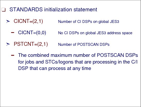
Specifies the maximum number of POSTSCAN DSPs that can operate in the JES3 global address space at any one time. The first subparameter (maxbatch) indicates the maximum number of POSTSCAN DSPs that can process batch jobs. The second subparameter (maxdemsel) indicates the maximum number of POSTSCAN DSPs that process demand select jobs (that is, started tasks and TSO LOGONs). A POSTSCAN DSP defined as processing batch jobs cannot be used to process demand select jobs, and vice versa.
The total of both numbers specified for this parameter must be between 1 and 32,767 (inclusive).
STANDARDS statement parameter for CI
The STANDARDS initialization statement has the following parameters:
CICNT Specifies the maximum number of CI DSPs that can operate in the JES3 global address space at any time. The first subparameter (maxbatch) specifies the maximum number of CI DSPs that process batch jobs. The second subparameter (maxdemsel) specifies the maximum number of CI DSPs that process demand select jobs (that is, started tasks and TSO LOGONs).
DEFAULT: (2,1)
PSTCNT This parameter specifies the number of active POSTSCAN FCTs in the JES3 global address space.
Postscan processing takes place in the global address space for all jobs that go through their JCL conversion/interpretation and PRESCAN in an FSS address space and for job that have been rescheduled for postscan.
DEFAULT: (2,1)
7.8 Jobs entering CI processing
Jobs processing in CI
The CI, POSTSCAN, and CICLENUP driver module (IATIIDR) provides for the logical flow of jobs through C/I processing, global locate processing, job summary table creation for MDS. IATIIDR handles the postscan phase by loading and calling the postscan module (IATIIPN).
Converter/interpreter seven processing modes
The “mode” of a DSP determines the type of processing performed for a job in C/I service. Mode is dependent on the type of DSP (CI, POSTSCAN, or CICLENUP) and the environment where the DSP is running (JES3 global or C/I FSS address space).
CI DSP modes
There are three modes for the CI DSP as follows:
1. JES3 C/I mode (CI DSP) -- The DSP runs in the JES3 global address space and processes a job through MVS C/I, prescan and postscan.
2. FSS C/I mode (CI DSP) -- The DSP runs in a C/I FSS address space and processes a job through MVS C/I and prescan. The job must be returned to the JES3 global address space for postscan processing.
3. C/I FSS demand select mode (CI DSP) -- The DSP runs in the JES3 global address space and processes a demand select job used to start a C/I FSS address space through MVS C/I, prescan and postscan. MVS C/I is performed using the special C/I FSS demand select subtask.
There are two modes for the POSTSCAN DSP as follows:
4. Postscan mode (POSTSCAN DSP) -- The DSP runs in the JES3 global address space and processes a job (that has successfully completed MVS C/I and prescan in a C/I FSS address space) through postscan.
5. Reschedule mode (POSTSCAN DSP) -- The DSP runs in the JES3 global address space and processes a job (that was rescheduled after MVS C/I and prescan) through postscan. A dependent job control (DJC) job is rescheduled if its predecessor jobs have not completed.
– Locate processing is performed on a processor that is eligible to run the job. If an eligible processor is not available, the job is rescheduled.
– The JES3 global address space may terminate before a job, (that has completed MVS C/I and prescan in a C/I FSS address space) can be scheduled for postscan. The job is scheduled for postscan after JES3 is restarted.
There are two modes for the CICLENUP DSP as follows:
6. Cleanup/cancel mode (CICLENUP DSP) -- The DSP runs in the JES3 global address space and performs cleanup processing for a job that either has failed C/I in a C/I FSS address space or was cancelled.
7. Cleanup/reschedule mode (CICLENUP DSP) -- The DSP runs in the JES3 global address space and performs cleanup processing for a job that is being rescheduled for postscan by CIDRVR. The CIDRVR DSP reschedules a job for postscan if it is a member of a DJC network whose predecessor jobs have not completed, or if no eligible processors are available for locate processing. JSS will schedule the job for postscan when the job is eligible.
7.9 Converter/Interpreter service phases
JES3 job interpretation
When JES3 has a job that can be scheduled for C/I processing, it determines whether a CI DSP in the JES3 global address space or a C/I FSS address space is available for the job. At the end of interpretation, the storage management subsystem (SMS) scans the SWA control blocks to determine the required catalogs for new data sets. Catalogs for jobs can be SMS-managed or JES3-managed. SMS uses the list of SMS-managed volumes to determine which mains are eligible for catalog searches. A list of catalogs that are not SMS-managed is returned to JES3 and becomes part of JES3's setup requirements. When the C/I subtask finishes its work, the job enters the prescan phase of C/I service.
Converter/interpreter phases
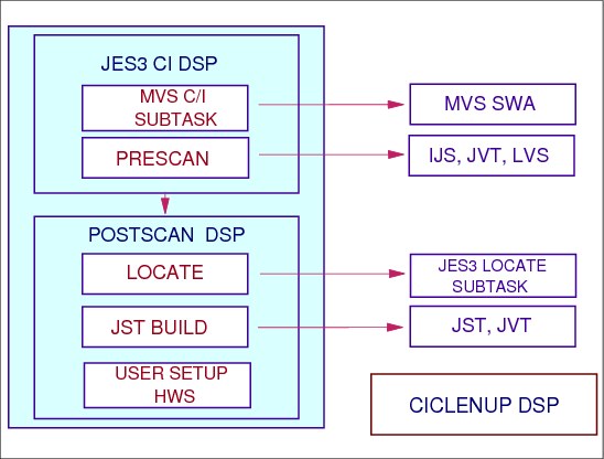
The CI, POSTSCAN, and CICLENUP DSPs perform the actual converter/interpreter processing. The converter/interpreter service comprises primarily the JES3 CI and POSTSCAN DSPs, the C/I subtasks under which the MVS C/I routines run, and the initiator support routines. You can define one or more C/I functional subsystem (FSS) address spaces to perform the converter/interpreter, prescan, and locate (catalog search) portion of the postscan phase for some or all jobs. A C/I FSS can operate on the global or any local main. All of the C/I FSSs are controlled from within the JES3 global by the CIDRVR DSP.
MVS C/I subtask
The CI DSP for processing includes setting up the MVS C/I subtask. For example, the IDD (the DSP's data CSECT) is initialized with the procedure library and C/I parameter information to be used by the C/I subtask from the job's JDAB (job data and accounting block). The C/I subtask phase can be performed in the JES3 global or a C/I FSS address spaces and consists of calls to the MVS converter to convert the job's JCL into converter/interpreter text, and to the MVS interpreter, to convert the converter/interpreter text into SWA control blocks. Most of this processing is done under a CI subtask to isolate the JES3 nucleus task from implied WAITs and abends. All of the C/I FSSs are controlled from within the JES3 global by the CIDRVR DSP.
Prescan phase
The primary function of the prescan phase is to extract each job's resource requirements from the SWA control blocks created in the interpreter phase. On entry to the prescan phase, JES3 examines the SETUP parameter on the JES3 STANDARDS initialization statement:
•If you specify SETUP=NONE (that is, you do not want JES3 to perform pre-execution setup for the complex), JES3 does not build extract resource requirements.
•If you specify any value other that NONE on the SETUP= keyword, JES3 determines the job's resource requirements.
During the prescan phase, the JCL for the job is examined for PGM=JCLTEST or PGM=JSTTEST. If PGM=JCLTEST is found on an EXEC statement, the JCL is interpreted and the job is then express canceled on completion of the CI DSP. If PGM=JSTTEST is found on an EXEC statement, the job is processed through the prescan and postscan phases, a printed format of the job summary table (JST) is printed on the JESYSMSG data set, and the job is then canceled-with-print on completion of the CI DSP. Installation exits IATUX04, IATUX05, and IATUX06 allow you to examine or change job, step, and DD information, respectively. You can use these exits to examine or change the information before processing begins. For more information on JCLTEST and JSTTEST, see z/OS JES3 Diagnosis, GA22-7547.
If the job is being processed in a C/I FSS, JES3 determines whether the job is eligible to have catalog searches performed on the main where the C/I FSS is executing. If catalog searches can be performed on that main, locate processing occurs in the C/I FSS and control then returns to the JES3 global address space for the remainder of postscan processing.
Prescan phase control blocks
The prescan phase uses the SWA control blocks to build tables used in postscan processing. Prescan builds the intermediate job summary table (IJS), the locate request table (LVS), and the job volume table (JVT); these specify required resources for the job. Prescan also writes SWA control blocks to spool for later use during the job select for execution process.
IJS Intermediate job summary table (IJS) contains an entry for each DD statement that requires a JES3-managed or SMS-managed device An IJS entry is also created when volume and unit information is not specified, which means that the catalog must be searched to determine whether the device is JES3-managed.
JVT Job volume table (JVT) contains an entry for each volume (needed by the job) that requires a JES3-managed device. Each JVT entry is associated with the IJS entry for that DD statement.
LVS The locate request table (LVS) contains an entry for each data set that requires a catalog search to obtain unit and volume information. The data set is assumed to require a volume on a JES3-managed device until the catalog is searched. Each LVS entry is associated with the IJS entry for that data set.
Postscan phase
The functions of the postscan phase are to resolve cataloged data set references and prepare the job for the main device scheduler (MDS). The POSTSCAN DSP runs in the JES3 global address only. It performs postscan processing for a job that has already completed MVS C/I and prescan. For example, the CIDRVR schedules a job for postscan after it successfully completes MVS C/I and prescan in a C/I FSS address space. JSS schedules a job for postscan when the job is a DJC job and all of its predecessor jobs have completed.
LOCATE processing
Also called cataloged data set resolution. If SMS is active, JES3 calls it to search the system catalogs and collect scheduling information for the job. SMS searches the system catalogs to obtain information about a job's data sets when the job's JCL does not specify unit information. If SMS fails to find a data set name, the postscan phase calls installation exit IATUX07 (Examine/Substitute Unit Type and Volume Serial Information). Through this installation exit, you can examine the available data set information and, if necessary, supply the unit and volume information. If a data set has been migrated (or is eligible to be migrated) by the Hierarchical Storage Manager (HSM), the LOCATE request for that data set causes JES3 to associate the data set with a set of volumes to which it can be recalled. HSM limits the choice of volumes eligible for recall during LOCATE processing in accordance with its space management algorithms. JES3 processing continues as though the data set is recalled to all eligible volumes. However, the actual recall does not occur until job execution when MVS issues a LOCATE request. At that time, HSM determines which volume is the best choice to recall the data set to and then recalls the data set to that volume. HSM derives an SMS storage class and an SMS storage group for SMS-managed data sets.
JST build
Although the JES3 main device scheduler performs volume fetching and setup, JES3 must determine the type of setup used for each job. You specify the type of job setup by coding the SETUP parameter on the JES3 STANDARDS initialization statement or the end user can override your specification using the SETUP parameter on the //*MAIN statement in a job's JCL. The IJS and JVT are used to create the job summary table (JST). The JST contains a summary of the job's data set, volume, and unit requirements. The JST is built so that all of the job's resources are allocated before the job executes. (This is known as "job setup".)
User setup
User setup override processing is invoked if the user specifies setup and fetch overrides on the //*MAIN statement. If so, the JST is modified to reflect those requirements.
HWS setup
High-watermark setup processing (HWS) is used if the installation specifies the high-watermark setup algorithm. The JST is modified so that the minimum number of devices required to run the job are set up.
CICLENUP DSP
The CICLENUP DSP runs in the JES3 global address space only. It performs cleanup processing such as updating control blocks and issuing error messages. A separate DSP is used for cleanup processing because it may require I/O to read and checkpoint the job's control blocks. It is set up by the CIDRVR when one of the following occurs:
•A job fails C/I in a C/I FSS address space
•A job is cancelled while it is in a C/I FSS address space, or while it is waiting for the CIDRVR to schedule it for postscan
•A job must be rescheduled for postscan because there are no eligible processors to perform locate processing. A processor is "eligible" if it is connected, on-line and in the job's main mask.
•A job is a member of a DJC network and its predecessor jobs have not completed
7.10 CI global processing overview
CI processing overview
A CI DSP exists for one main reason: to gather information concerning the job's device, volume, and data set requirements prior to MVS execution of the job. This information is necessary for pre-execution setup, one of the major facilities of JES3. The information is taken from DD statements in the job's JCL. The CI DSP serves as an interface between JES3 and the JES3 CI subtasks that invoke the MVS converter/interpreter. The interface subtask (IATIIST) processing for a job includes:
•To fail the job if JCL errors are detected by the MVS converter/interpreter.
•To fail any job that contains more JCL statements than the limit allows.
•To delay processing of any job that would temporarily cause the C/I subtasks to process more JCL statements than the system limit allows.
•To set up security environment for converter and open procedure libraries
•To call the MVS converter and MVS interpreter
•To copy the SWA control blocks that are produced by the MVS converter/interpreter onto spool.
Converter Interpreter processing begins in module IATIIDR under the CI FCT, continues under the POSTSCAN FCT, and is completed under the CICLENUP FCT.
Pre-execution phases
These DSPs driver module processing includes several functional phases:
Converter and interpreter phases
The beginning phase includes setting up the CI DSP for processing. For example, the DSP's data CSECT (IATYIDD) is initialized with information from the job's JDAB (job data and accounting block). This phase is performed in both the JES3 global and C/I FSS address spaces.
The interpreter phase includes converting and interpreting a job's JCL. This phase consists of calls to the MVS converter to convert the job's JCL into C/I text, and to the MVS interpreter, to convert the C/I text into SWA control blocks. Most of this phase is done under a C/I subtask to isolate the JES3 nucleus task from implied WAITs and abends. If the converter detects any JCL syntax or logic errors, the job is printed and purged (and the MAIN scheduler element is bypassed). This phase is performed in both the JES3 global and C/I FSS address spaces.
Prescan phase
The prescan phase includes scanning the SWA control blocks created by the MVS interpreter and creates the following spool-resident control blocks:
•Intermediate job summary table (IJS) - The IJS contains an entry for each DD statement that requires a JES3-managed or SMS-managed device. An IJS entry is also created when volume and unit information is not specified, which means that the catalog must be searched to determine whether the device is JES3-managed.
•Job volume table (JVT) - The JVT contains an entry for each volume (needed by the job) that requires a JES3-managed device. Each JVT entry is associated with the IJS entry for that DD statement.
•Locate request table (LVS) - The LVS contains an entry for each data set that requires a catalog search to obtain unit and volume information. The data set is assumed to require a volume on a JES3-managed device until the catalog is searched. Each LVS entry is associated with the IJS entry for that data set.
These control blocks are used later, during the postscan phase, to create other control blocks used by JES3 setup processing. At the end of the prescan phase, the SWA control blocks are written to spool. They will be relocated in the user's address space when the job executes.
This phase is performed in the JES3 global and C/I FSS address spaces. If the job is executing in a C/I FSS address space, it is returned to the JES3 global address space for the postscan phase.
Postscan phase
This phase runs only in the JES3 global address space since it may require locate processing or catalog setup (catalog setup does not occur in the C/I FSS address space). The postscan phase performs the following functions:
•Locate processing - During locate processing the master and user catalogs are searched to obtain unit and volume information for each of the cataloged data sets referenced by the job. If the job's JCL specified JOBCAT or STEPCAT DD statements, the main device scheduler is used to set up the private catalogs before issuing locates. These catalogs are searched before any other catalogs.
•Next, the LOCATE FCT is posted to handle the locate request. The LOCATE FCT passes the request to the locate subtask. The locate subtask issues the actual MVS locate (SVC 26), and creates a response that contains the volume and unit information requested. When locate processing completes, the LOCATE DSP posts the waiting DSP. Then, the unit and volume information is used to determine if the data set will be managed by JES3. If so, additional JVT entries and, possibly, IJS entries are created.
•Job summary table creation - The IJS and JVT are used to create the job summary table (JST). The JST contains a summary of the job's data set, volume, and unit requirements. The JST is built so that all of the job's resources are allocated before the job executes. (This is known as “job setup”.)
•User setup/fetch override processing - The user can specify setup and fetch overrides on the //*MAIN statement. If so, the JST is modified to reflect those requirements.
•High watermark setup processing - If the user or the installation specifies the high-watermark setup algorithm, the JST is modified so that the minimum number of devices required to run the job are set up.
•JSTTEST processing - If the user specifies PGM=JSTTEST on an EXEC statement, a summary of the job's resource requirements is printed in the job's JESMSG data set.
•Ending phase
The ending phase involves cleaning up and returning the job to the appropriate FCT for further processing. If the job is executing in a C/I FSS address space, it is returned to the JES3 global address space for postscan, or for cancel processing if the job failed C/I. If the job is in the JES3 global address space, it is returned to the job segment scheduler (JSS) so that the next scheduler element can be scheduled. This phase is performed in the JES3 global and C/I FSS address spaces.
IATIIPS - POSTSCAN scheduler module
IATIIPS is called by JSS and the CI Driver FCTs to schedule a job for POSTSCAN. The CI driver calls IATIIPS when a job (which has completed MVS CI and PRESCAN in an FSS address space) is ready for POSTSCAN. A RQ is supplied.
When IATIIPS gets control, it first checks for an available batch or demand select POSTSCAN DSP. If there is an available POSTSCAN DSP it will be used. Next, the job's main mask is used to find an IPLed and online main processor for CI LOCATE processor and the job is setup for POSTSCAN DSP. A POSTSCAN FCT is initialized and the RQ chained and the FCT is attached to the FCT chain.
7.11 POSTSCAN phase
What was done in prescan phase
The prescan phase begun by determining any debug facilities being used and setting proper switches. IATIIDR loaded module IATIIPRE which contains C/I DSP PRESCAN Processor IATIIPR, Converter/Interpreter Compatibility IATIICM and SWA Block Spooling Routine IATIISP. Next, IATIIDR called the prescan module IATIIPR to create Intermediate Job Setup (IJS) entries, locate request data (LVS) entries, and Job Volume Table (JVT) entries and then spools the SWA control blocks for main initiation. Checkpointing of the IJS, LVS and JVT control blocks was then done to provide reschedule data from DJC or specialized reschedule jobs. The reschedule path reads these control blocks in for use in the postscan phase.
POSTSCAN phase
The functions of the postscan phase are to resolve cataloged data set references and prepare the job for the main device scheduler (MDS). Cataloged Data Set Resolution is performed by the JES3 Locate Function Driver Module (IATLVIN). The C/I Service Preparation for the Main Device Scheduler is done by the CI/POSTSCAN/CICLENUP Driver Module (IATIIDR).
The job segment scheduler calls the postscan scheduler module (IATIIPS) whenever a job is rescheduled for postscan processing. In CI FSS address space, the CIDRVR postscan scheduling routine (IATIIFS) calls IATIIPS whenever a job, which has completed MVS C/I and prescan processing in an FSS address space, is ready for POSTSCAN FCT processing.
The postscan scheduler module (IATIIPS) checks for an available batch or demand select POSTSCAN DSP for the job. Next, the job's main mask is used to find an IPLed and online main processor for locate processor, a POSTSCAN FCT is initialized, the job is added on the FCT’s RQ chain, and the FCT is attached to the FCT chain.
POSTSCAN DSP
The POSTSCAN DSP runs in the JES3 global address only. It performs postscan processing for a job that has already completed MVS C/I and prescan. For example, the CIDRVR schedules a job for postscan after it successfully completes MVS C/I and prescan in a C/I FSS address space. JSS schedules a job for postscan when the job is a DJC job and all of its predecessor jobs have completed.
LOCATE FCT
Locates are done during postscan processing under the LOCATE FCT. The locate function driver module (IATLVIN) receives requests for locate services to obtain information from the catalog about one or more datasets. To request locate services, a JES3 FCT chains a locate entry table (LET) anchored off of the locate data area (LDA). The LET contains the spool address of the locate request table (LVS). The LVS specifies the datasets that require locate processing. The global LOCATE FCT is responsible for determining where locates will be performed and sending the request to the correct main processor. The locate FCT on each processor is responsible for passing the request to a locate subtask to process. The locate subtask issues the actual MVS locates (SVC 26), and creates a response that contains the volume and unit information requested. After processing each request, the locate subtask creates a locate response (LRS) containing the information from the catalog.
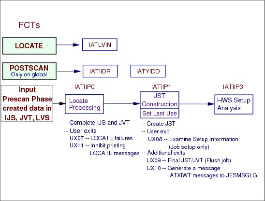
During the prescan phase, the Intermediate job summary table (IJS), job volume table (JVT), and locate request data (LVS) were constructed. The postscan phase is entered to resolve catalog data set references, complete construction of the job summary table (JST) from the IJS. If locate processing is required (an LVS exists), IATIIP0 issues locates to resolve all catalog data sets references.
POSTSCAN JST Build IATIIP1 builds the job summary table (JST) from the intermediate job summary table (IJS) and the job volume table (JVT). If job setup was specified, user exit IATUX08 is called whenever a job specifies or defaults to the job setup algorithm to examine the unit counts determined by IATIIP1. The last use of each volume, device, and data set is flagged in the JST. After examining the unit counts, IATUX08 either fails the job, continues with job setup, as specified, or sends the job through high-watermark setup to allocate the minimum number of devices for the job.
POSTSCAN High Watermark Setup Processing IATIIP3 is called during the postscan phase of CI, to perform high watermark setup processing. This involves determining the minimum number of units required to run the job being processed. The JST entries are updated according to the type of high watermark setup (e.g. tape hws).
In addition, whenever the response of a LOCATE request has been received, you can use installation exit routine IATUX11 (Inhibit Printing of the LOCATE Request/Response) to inhibit printing of the LOCATE request/response in the JESYSMSG data set.
7.12 Converter/interpreter exits

Converter/interpreter exits
The converter interpreter exits are as follows:
UX03 This is the internal text exit called during the convertor phase of C/I. The internal text for each JCL statement (some number of card images) is passed to this exit, one statement at a time.
The installation has the opportunity of changing the internal text to meet its need. This exit is prior to UX04, UX05, and UX06 and you can do the following in this exit:
– Control dispatching priority and performance groups
– Force VIO for certain DD statements
– Change non-existent UNIT= values to something supported in the installation, thus avoiding JCL changes.
UX04 This exit is called to allow the installation access to information obtained from the SWA related to the JOB (IATYJBL).
This is the recommended exit to verify accounting information. The exit is running in the C/I FSS address space (hopefully) and any delays in processing due to I/O or local lock contention will not adversely affect JES3 global's performance.
UX05 This exit is called to allow the installation access to information obtained from the SWA related to a job step (IATYSTP).
UX06 This exit is called to allow the installation access to information obtained from the SWA related to a DD statement within a step (IATYDDL). DUMMY, SYSIN and SYSOUT DD statements are NOT passed to the exit.
UX07 This exit is called whenever a LOCATE is unsuccessful. The installation has the option of providing the necessary information in order for the job to continue processing. If the exit does not provide information, the job will be failed. For jobs that fail C/I processing, user exit UX08 will not be called. User exit UX09 will be called in all cases.
This exit may use IATXIWT to write to the JESMSGLG data set. Should it use this service, user exit UX10 will get control.
UX08 This exit is called to allow the installation to determine what level of high water mark setup should be performed. The exit is only called when job setup is specified or defaulted. This exit or UX09 is most useful in placing a job in a particular job class based upon its physical resource requirements (e.g., tape drive).
This exit may use IATXIWT to write to the JESMSGLG data set. Should it use this service, user exit UX10 will get control.
UX09 This exit is called after highwatermark setup has been performed, or if the job has been failed earlier in the C/I or MDS phase.
This exit may use IATXIWT to write to the JESMSGLG data set. Should it use this service, user exit UX10 will get control.
UX10 User exits UX04, UX05 and UX06 are not able to write to the jobs JESMSGLG directly, this must be done using IATXIWT. If this service is used, exit UX10 is invoked to turn the message number (on the IATXIWT call) into text that will be written to the JESMSGLG data set. This exit is invoked under IATNUC or IATNUCF task.
UX11 This exit is called regardless as to whether the locate was successful or not. It has the option of having the locate responses printed or not printed in the JESMSGLG data set.
This exit may use IATXIWT to write to the JESMSGLG data set. Should it use this service, user exit UX10 will get control.
UX26 This exit is called repetitively as the SWA control blocks are read from spool. Any WTO's issued from this exit will appear in the JESMSGLG data set belonging to the initiator and not the job being placed into execution. The security environment for the job has not been established.
This is the last JES3 exit that can affect where SWA will be located for the job's execution phase.
UX41 This exit is after convertor processing has occurred and is called only if the job exceeds the installation number of allowed JCL statements (not card images). The exit can allow the job to proceed or fail the job at this time.
This doesn't prevent the user from submitting a job stream that has 200,000 JCL statements and causing virtual storage failures. The output of the convertor is kept in storage that is below the 16M line. You will have to use an SMF exit to prevent this from occurring.
UX46 This exit is called to allow the installation to influence whether a job will go through C/I on the global processor or on one of the processors having a C/I FSS address space. It has a partner exit in this process, exit 49.
UX49 This exit is called after an address space has been selected by JES3 for the C/I process based upon information from the previous user exit and the job's main mask. The installation can accept or reject JES3's decision. The exit will be iteratively called as long as JES3 has alternatives. If the exit does not find a suitable address space for the C/I, the job will be failed.
7.13 C/I FSS address space
C/I FSS address space
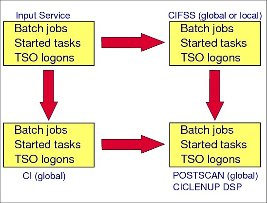
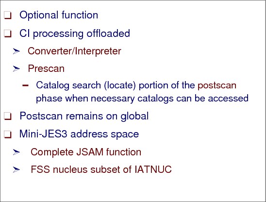
The primary advantage of using the optional C/I FSS address spaces is to off-load much of the overhead caused by converter/interpreter processing from the global address space.
The C/I FSS address space can be on any MVS system in the complex. The scheduling of the CI scheduler element is still done by JSS in the global address space.
The postscan function for a job are done in the JES3 global address space. The CI DSPs that run in a C/I FSS address space process jobs through the converter/interpreter and prescan phases of C/I service. JES3 can also perform the catalog search (LOCATE) portion of the postscan phase in a C/I FSS if the main where the CI FSS runs has access to the necessary catalogs.
The CI FSS address space has certain JES3 global address space functions available in the CI FSS. These functions are:
•A modified JES3 nucleus, called IATNUCF
•A modified resident FCT chain
•JSAM I/O
•Trace facility via IATXTRC- Makes an entry in a JES3 trace table
•Storage management queue via IATXSQE - is used to add or delete an entry from the storage management queue
•ABEND/FAILSOFT capability
7.14 C/I FSS TCB structure
C/I FSS TCB Structure
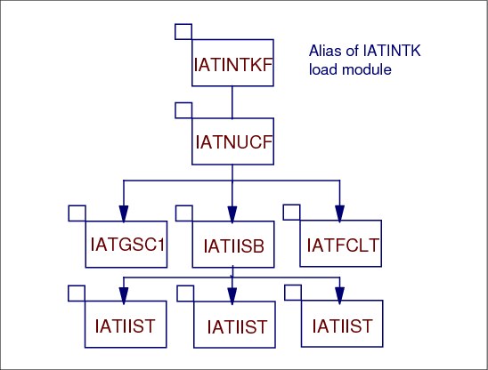
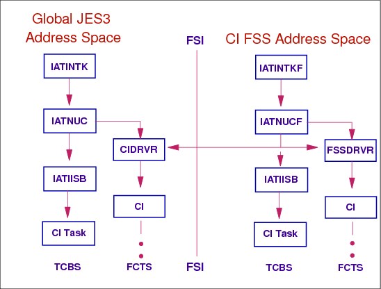
In the FSS address space, the first task is IATINTKF. This name appears on the EXEC statement in the procedure used to start a C/I FSS address space. IATINTKF is an alias of IATINTK. An alias is required because the JES3 and FSS tasks have unlike program properties. For example, JES3 is non-cancellable, so IATINTK is defined as non-cancellable in the MVS program properties table. However, an FSS address space can be cancelled so another entry point is defined (IATINTKF).
In the JES3 global address space, IATINTK attaches the JES3 nucleus task, IATNUC. In the C/I FSS address space, IATINTKF attaches the FSS nucleus task IATNUCF. IATNUCF contains a subset of the routines contained in IATNUC.
During C/I subtask initialization, IATNUC or IATNUCF attaches module IATIISB, the master C/I subtask. IATIISB's function is to attach the C/I subtasks that interface with the MVS converter and MVS interpreter. The C/I subtask resides in module IATIIST. These subtasks are divided into three types, depending on the type of jobs they process.
In the C/I FSS address space, IATNUCF attaches a listen subtask (IATFCLT) as a result of an FSS CONNECT. IATFCLT receives order and post FSI requests from the JES3 global and, using the proper FSI interface routine, passes them to the FSS or FSA for processing.
The figure shows three CI subtasks (IATIIST).
7.15 C/I initialization statement - FSSDEF

FSSDEF statement
Use the FSSDEF statement to define the characteristics of a functional subsystem (FSS) which operates in its own address space. Use a FSSDEF statement to define one or more C/I FSSs.
FSSNAME Specifies the name of a WTR FSS for which this printer is to be associated.
PNAME Specifies a member of the procedure library for started task jobs, which contains a cataloged procedure for starting the FSS. The member must be in the procedure library defined by the STCPROC parameter of the STANDARDS statement, or in procedure library IATPLBST, if the STCPROC parameter is omitted.
TERM Identifies whether or not the FSS terminates if the JES3 global terminates as the result of an *RETURN or *DUMP operator command.
SYSTEM Specifies the JES3 main on which the FSS is to operate. The name(s) must be the same as specified on the NAME parameter of the MAINPROC statement for the main.
DSPCNT Specifies the maximum number of CI DSPs that can operate in the C/I FSS address space at any time. The first subparameter (nnn) specifies the maximum number of CI DSPs that process batch jobs. The second subparameter (nnn) specifies the maximum number of CI DSPs that process demand select jobs (that is, started tasks and TSO LOGONs).
START Specifies whether or not JES3 should start the FSS automatically when the main on which the FSS is to run is connected to the global. This parameter applies only to C/I FSSs. If specified for an output writer FSS, this parameter is ignored.
MAXASST Specifies the maximum number of JCL statements that can be processed concurrently by all CI DSPs in the C/I FSS address space. The value must be an integer between 0 and 99999999, inclusive. A value of 0 means no JCL statement limit applies; JES3 does not check how many JCL statements are being processed.
CI/FSS procedure
f C/I FSS address spaces are used, a cataloged procedure for starting the C/I FSS address spaces must be defined. Include the procedure for starting the a C/I FSS address space in an appropriate procedure library. A sample C/I FSS start procedures are in SYS1.SIATSAMP library in the members IATJ3CI and JES3CI. Always specify the same checkpoint data set(s) as specified in the JES3 start procedure and use DISP=SHR.
MAXASST Specifies the maximum number of JCL statements that may be processed concurrently for all CI DSPs in both the JES3 address space and C/I FSS address spaces.
The MAXASST keyword on the FSSDEF statement defines the number for an C/I FSS address space.
Demand select jobs are excluded from the limit function.
DEFAULT: 0
BUFFER statement
The converter/interpreter DSP requires JSAM I/O. The CI FSS supports JSAM I/O in the C/I FSS address space.
The BUFFER statement specifies of the number of JSAM buffers in the C/I FSS address space.
global Specifies number of pages for JES3 global address space.
local Specifies number of pages for JES3 local address space.
cifss Specifies the number of pages for a CI FSS address space.
Defining number of CI and POSTSCAN DSPs
The combined maximum number of CI and POSTSCAN DSPs in all address spaces equals the maximum number of jobs that C/I service can process at any time. Increasing the number of CI DSPs in any address space allows C/I service to process more jobs concurrently in that address space and in the JES3 complex. However, a CI DSP in a C/I FSS address space that has finished processing a job is considered "in use" until a POSTSCAN DSP becomes available. The number of POSTSCAN DSPs, therefore, can limit the number of CI DSPs in a C/I FSS address space that are actively processing jobs.
7.16 Starting a C/I FSS address space
Starting a CIFSS address space
When an FSSDEF statement for CI is processed during JES3 initialization, module IATINI1 loads all modules necessary to provide this function. A CIDRVR FCT is chained into the FCT chain to provide communication with a C/I FSS address space. (The CIDRVR DSP controls all of the C/I FSSs from within the JES3 global address space.)
Following JSS first pass processing, the CIDRVR FCT in module IATIICD will get control to start the C/I FSS address spaces.
This is done in module IATIIFS by issuing the IATXFSS TYPE=START,PARM=(R0),... macro request. The IATXFSS macro passes control to JES3 global FSS/FSA services (IATGRFS) at the entry point corresponding to the TYPE= function specified.
The PARM=(R0) on the macro allows specification of a parameter string. Module IATGRFS gets control when this macro is issued and builds and issues the start command.
START command for FSS
The START command has the following format:
S PROCNAME.FSSNAME,,,(SSID,FSSID,PARM)
Where:
SSID is the name of the subsystem (JES3 for example)
FSSID is functional subsystem ID in zoned decimal format
PARM is the parameter data to be passed to the FSS
IATGRFS sends (JSERV) the start command to the system specified on the FSSDEF statement.The START command will be issued internally (MGCRE macro) with a program token.
|
Restriction: The cataloged procedure for starting an FSS should not use any JCL symbols. The JES3 generated internal start command does not support any overriding keyword parameters.
|
Command to modify DSPC count
A C/I FSS is ended by JES3 in response to one of the following:
•A *F F,FSS=fssname,DSPC=(mmm,nnn) command is entered for a C/I FSS, changing both DSP count values to zero.
•An MVS CANCEL command is entered that specifies a C/I FSS name.
Command to display FSS information
The *I,F command to displays:
•The attributes and current status of the FSS
•Information for all FSSs of a particular type (WTR, C/I), whether active or inactive
•Maximum counts and status information for C/I service DSPs running in a C/I FSS.
7.17 C/I FSS communication
C/I FSS address space communication
The C/I FSS address spaces are controlled from the JES3 address space by a single CIDRVR FCT entry.
•The CI driver DSP module is IATIICD. IATIICD initializes the CI driver FCT. It gives control to the proper routine when the CI driver is posted. IATIICD also contains the CI driver's console appendage, JESTAE exit, and JESTAE retry routine.
IATIICD controls C/I processing in either a C/I FSS or JES3 global address space. This includes the following:
– Starting the C/I FSSs and controlling the various phases of a C/I FSS's initialization
– Processing operator commands related to the C/I FSSs
– Processing CANCEL and FAIL commands for jobs in the C/I FSS address spaces
– Cleaning up after a C/I FSS terminates
– Scheduling jobs for postscan (see “The POSTSCAN DSP”) after they have successfully completed MVS C/I and prescan in a C/I FSS address space
– Scheduling jobs for cleanup processing if the job fails MVS C/I in an FSS address space, or is cancelled
– Causing the C/I FSSs to enable and disable procedure libraries when a job updates one or more procedure library data sets.
•All operator commands related to CI processing are handled by the JES3 address space.
•All C/I FSS address spaces must be defined via the FSSDEF initialization statement.
In the C/I FSS address space, module IATINTK has an entry point IATINTKF. IATINTK attaches the C/I FSS address space nucleus module IATNUCF.
FSSDRVR DSP
The FSSDRVR DSP (module IATIIFC) controls a single FSS address space from within that address space. This includes the following:
•Controlling the various phases of a C/I FSS's initialization
•Setting up a CI FCT for each job that is sent to the C/I FSS address space by JSS
•Returning jobs that have completed C/I processing to the CIDRVR in the JES3 global address space
•Enabling and disabling procedure libraries, if requested by the CIDRVR
•Cancelling and failing jobs, if requested by the CIDRVR
•Processing operator *F commands, if requested by the CIDRVR.
A C/I FCT executing in the FSS address space has also the IATIIDR as the driver module.
Functional subsystem interface
JES and the FSS/FSA communicate through the functional subsystem interface (FSI). The FSI is a one-level interface which provides two way communication. The FSI consists of a set of macro-invoked service routines provided by both JES and the FSS/FSA. These service routines are:
•JES routines that reside in the FSS address space
•SSI routines that JES provides
•FSS/FSA-supplied routines.
– Functional subsystem (FSS) is an address space uniquely identified as performing a specific function related to the JES.
– Functional subsystem application (FSA) is the functional application program managed by the functional subsystem.
7.18 C/I FSS FCTs
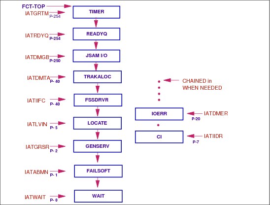
CIFSS FCTs
This figure shows the resident FCT chain in the CI FSS address space.
When a job is scheduled to this address space for converter processing, a CI FCT is added to the FCT chain. These are the only FCTs necessary for processing the converter interpreter.
FSSDRVR FCT
The FSSDRVR, module IATIIFC, controls a single FSS address space from within that address space. It controls the following:
•Initializing C/I FSS's (various phases)
•Setting up the C/I FCT
•Returning jobs to CIDRVR in the JES3 global address space
•Enabling and disabling the procedure libraries
•Processing modify commands
FSSDRVR processing
When an ORDER is sent by the JES3 global, FSSDRVR is posted.
7.19 C/I FSS FSI CONNECT to global

CIFSS FSI CONNECT to global
The functional subsystem interface (FSI) allows communication between JES and your functional subsystem (FSS) and functional subsystem application (FSA). A functional subsystem (FSS) is a collection of programs residing in an address space separate from JES that communicates with JES to provide a JES-related function. An FSS extends the scope of JES processing.
Note: C/I FSS address spaces do not use FSAs.
JES and the FSS/FSA communicate through the functional subsystem interface (FSI). The FSI is a one-level interface which provides two way communication. The FSI consists of a set of macro-invoked service routines provided by both JES and the FSS/FSA. These service routines are:
•JES routines that reside in the FSS address space
•SSI routines that JES provides
•FSS/FSA-supplied routines.
The FSS/FSA and JES use the FSIREQ macro to invoke functional subsystem interface (FSI) services. The FSIREQ macro allows JES to issue orders to the FSS/FSA and the FSS/FSA to issue requests to JES.
FSI communication services
The functions of the individual FSI communication services are:
•FSI CONNECT -- The FSS and FSA invoke the FSI CONNECT service to establish the functional subsystem interface to JES. FSI CONNECT processing tells JES that the FSS/FSA is started. It also identifies to the FSI the addresses of FSS/FSA routines that are to receive control when JES issues the FSIREQ macro and the addresses of JES routines that are to receive control when the FSS/FSA issues the FSIREQ macro.
•FSI DISCONNECT -- The FSS and FSA invoke the FSI DISCONNECT service to terminate connection with JES.
•FSI ORDER -- JES invokes the FSI ORDER service to issue orders to the FSS/FSA. When an operator issues a JES command that requires the participation of an FSS/FSA, JES converts that command into an order. An order represents a unit of work known to both JES and the FSS/FSA. The FSS/FSA performs the actions associated with the order and then responds to JES with the required information.
JES3 starts the FSS address space
Whenever an FSS is eligible to be started the CIDRVR “driver IATIICD” is posted. The driver invokes a service routine to start the FSS. The service routine causes a START command to be issued on the main processor where the FSS is to run. However, before the C/I FSS can process jobs, start up and initialization must be performed. Module IATINFC receives control after the JES3-related initialization is complete. C/I FSS Initialization module IATINFC handles C/I FSS specific initialization including creating tables and loading modules used during C/I processing. Then, control is passed to the FSSDRVR FCT (module IATIIFC) to issue the FSS CONNECT that informs the CIDRVR that the FSS has completed the first phases of initialization.
CIDRVR FCT on global
After the CIDRVR receives the FSS CONNECT, it sends a PROCLIB (TYPE=BUILD) ORDER to begin the C/I FSS's procedure library initialization. The FSSDRVR creates the procedure library and dynamically allocates the procedure libraries. Once procedure library initialization completes successfully, the FSSDRVR sends a PROCLIB (TYPE=BUILD) response to the CIDRVR. When the CIDRVR receives the PROCLIB response, it checks if the CI DSP counts are still non-zero and, if so, sends a MODIFY COUNT (TYPE=INIT) ORDER to start the FSS's C/I subtask initialization. If successful, the FSSDRVR sends a MODIFY COUNT (TYPE=INIT) response to the CIDRVR and the C/I FSS is considered ready for work.
7.20 Schedule a Job for C/I FSS

Schedule a job for C/I FSS
The job segment scheduler (JSS) on the global is responsible for scheduling jobs for C/I.
A JES3 macro, (IATXCIO TYPE=), is used to send orders to the C/I FSS address space. All calls through IATXCIO enter module IATIIOR where the JSERV macro is used to send order staging area to the C/I FSS address space. An IATXCIO TYPE=PJCI request specifies that the C/I FSS address space should process the job.
In the C/I FSS address space, the CIDRVR builds a RQ and CI FCT and obtains a CI subtask. The selected job then goes through converter interpreter processing.
POSTSCAN on global
The job is then returned to the global where it is updated and the job is now placed onto the POSTSCAN queue to continue CI processing.
7.21 Operator control of CI subtasks

Operator control of CI subtasks
The *I X,D=CI command displays the current number of CI subtasks. The messages text shows:
•Whether they can be modified, MOD=YES
•Whether CI is in hold
•The MAXASST JCL limit
During JES3 initialization, the system programmer specifies the number of copies of the C/I DSPs and POSTSCAN DSPs to be used by C/I service. The JES3 STANDARDS initialization statement and the FSSDEF initialization statement define the number of C/I DSPs and POSTSCAN DSPs that are to be used by batch jobs and started task jobs and TSO/E LOGON jobs. The number of copies of the C/I DSPs and POSTSCAN DSPs can be modified with the *F X command.
These counts can be modified for CI FSS address spaces and for the number of subtasks on the global.
7.22 Display CI processing status of a job

Display CI processing status
The *I J= command displays the status of a job, which scheduler element is the current one. When the current scheduler element is CI, the status is shown as follows:
CI(status)
CI(Status)
The C/I scheduler element is ready to be, or is being, processed for the job. If the element is not being processed, only 'CI' appears in the message. Otherwise, status indicates where the job is processing in C/I processing. Inquiries on the POSTSCAN DSP also display 'CI' since the POSTSCAN DSP runs under the C/I scheduler element.
CI(Status) values
The CI status displayed may have following values:
CS The job is in catalog setup (JOBCAT or STEPCAT DDs)
CF The job is active in C/I and PRESCAN processing in a functional subsystem (FSS) address space. In this case, the FSS name of the CI FSS that is processing the job is also displayed.
A The job is active in C/I and PRESCAN processing in the JES3 address space.
PS The job is active in POSTSCAN processing in the JES3 address space.
LC LOCATE processing is being performed for the job.
WP The job is waiting to be scheduled for POSTSCAN processing. The name of the FSS that the job is associated with is also displayed.
* The C/I scheduler element was ended by JES3 FAILSOFT processing.
R The CI DSP had specified rescheduling because a main was not available to do LOCATE processing, or the job is in DJC hold status.
Other message text and response
No specific action is required if this message is issued in response to a command. If it is issued during restart processing, cancel the indicated job when restart processing is complete. The only commands that JES3 can accept for the job are *I and *F jobno,C.
FSS=fssname fssname identifies functional subsystem (FSS) name.
MPNAME=mpname mpname identifies the main processor name.
7.23 Change CI status

Change CI status
The CI and DISABLE scheduler elements status for scheduling can be changed with the *F X operator command. HOLD or RELEASE parameters specify that C/I or DISABLE DSP activity should be stopped (HOLD) or resumed (RELEASE).
The *F X= command can also change the MAXASST parameter and the MAXJOBST parameter for the C/I DSP.
•MAXASST=xxxxxxxx -- Specifies the maximum number of JCL statements that can be processed simultaneously in the JES3 global address space.
•MAXJOBST=yyyyyyyy -- Specifies the maximum number of JCL statements to be allowed in a single job.
DSP dictionary HABLE parameter
The *F X,HOLD or *F X,RELEASE command is enabled for DSPs by specifying the HABLE parameter in the DSP dictionary entry for the DSPs. HABLE is specified as follows:
HABLE=YES Allows the DSP's work to be held and released by the *F,X,D=dsp,HOLD and *F,X,D=dsp,RELEASE commands. For DSPs that have an FCT, the command takes affect immediately upon being issued. For DSPs having no FCT, the command prevents the job segment scheduler (JSS) from scheduling the DSP.
HABLE=NO Disallows the DSP's work to be held and released by the *F,X,D=dsp,HOLD and *F,X,D=dsp,RELEASE commands.
The default settings for DISABLE and CI is HABLE=YES. The default for the POSTSCAN DSP is HABLE=NO.
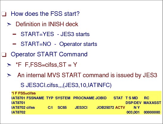
Stopping an C/I FSS address space
Several attributes assigned to a functional subsystem (FSS) can be modified, allowing an installation to balance its workload and prevent bottlenecks. For example, if your current workload is heavy, you can have JES3 start a C/I FSS, which has a non-zero DSP counts, by modifying the start value (ST) for that FSS from NO to YES.
JES3 stops an active C/I FSS address space when the maximum number of C/I DSPs is set zero (0).
*F F,FSS=cifss,DSPC=(0,0)
|
Note: The start value (ST) for that FSS is set to NO when the C/I FSS address space is terminated.
|
The MVS CANCEL command ends an active job, started task, or time-sharing user immediately.
CANCEL [jobname.]cifss [,A=asid] - End a started task
The identifier cifss is the same that was specified on the FSS START command (the ffsname on the FFSDEF initialization statement).
Stopping the global processor -*RETURN
Issue the *RETURN command to end JES3.
*RETURN,FSS=(cifss,..)|ALL|NONE - on global
The FSS=fssname or (fssname,fssname...) or ALL or NONE parameter specifies that a specific functional subsystem (fssname), several functional subsystems (fssname,fssname...), all functional subsystems (ALL), or no functional subsystems (NONE) are to be ended also. (This command is valid only when entered from the global.)
If FSS= is not specified, the status of the functional subsystems depends upon the value defined in the TERM= parameter of the FSSDEF initialization statement.
7.24 INQUIRY/MODIFY POSTSCAN

INQUIRY/MODIFY POSTSCAN
The number of POSTSCAN FCTs can be controlled via operator command. You can display the current number, *I X,D=POSTSCAN.
You can modify the current counts, *F X,D=POSTSCAN,MC=(x,x).
POSTSCAN FCT counts are specified on the STANDARDS statement.
You can display the current jobs that are active under the POSTSCAN FCTs as follows:
*I A,D=POSTSCAN
You can also display the jobs waiting for the POSTSCAN FCT;
*I Q,D=POSTSCAN
7.25 JES3 proclib update facility
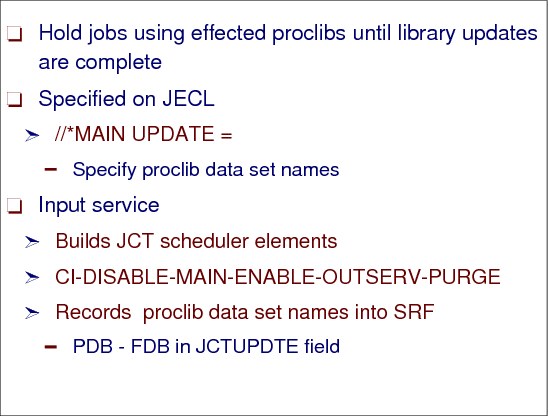
JES3 proclib update facility
The JES3 proclib update facility allows users to update one or more procedure library data sets using the UPDATE keyword on the //*MAIN statement. Input Service creates a JCT for the proclib update job with two additional scheduler elements: DISABLE and ENABLE.
Procedure libraries
The installation can define one or more procedure libraries to JES3 by specifying the data sets and DD-names in the JES3 start procedure, or on the DYNALLOC JES3 initialization statement. The procedure libraries are allocated during JES3 initialization and also by the C/I FSSs, since the MVS converter also runs in a C/I FSS address space.
UPDATE parameter
An UPDATE parameter on the //*MAIN statement causes all jobs using the identified procedure library data sets and any concatenated data sets to be held until the procedure library update is complete.
Input service validates the data set names specified on the UPDATE keyword on the //*MAIN statement and creates a procedure library data set block (PDB) for them. Input Service also creates a JCT for the job with two additional scheduler elements: DISABLE and ENABLE. These scheduler elements appear before and after the MAIN scheduler element, respectively.
To prevent new jobs from updating the procedure library, change the DISABLE DSP maximum use count to 0 or issue the *F,X,D=DISABLE,HOLD command. To resume updating, increase the DSP maximum use count or issue the *F,X,D=DISABLE,RELEASE command.
Proclib update considerations
|
Note: If you use the proclib update facility to move a procedure library to another volume, and the procedure libraries are allocated through the JCL statements in the JES3 cataloged start procedure, The JES3 local address spaces must be restarted in order to:
|
1. Reallocate the procedure library on the new volume. This is necessary if a JES3 local processor is a DSI candidate. Before a DSI is performed, all locals, which are DSI candidates must be restarted in order to pick up the change.
2. Vary offline the volume containing the old procedure library. During proclib update processing, the JES3 global and C/I FSS address spaces unallocate the procedure libraries being updated. However, the JES3 local address spaces do not unallocate the proclibs during proclib processing. This causes the VARY command for the proclib to fail when you attempt to vary the proclib offline to one of the local processors.
The JES3 local address spaces do not have to be restarted if the procedure libraries are defined via the DYNALLOC statements in the initialization stream.
|
Attention: If a job that updates a procedure library is in a JES-managed job class group, and it is updating the procedure library used to start initiators, make sure that there is at least one initiator started before allowing the job to enter the system. Otherwise, a deadlock will occur; the procedure library used to start the initiator is disabled, the job is waiting for an initiator, and the initiator is waiting for the procedure library to be enabled. If this situation arises, the updating job must be cancelled and resubmitted or a *RESTART,SETUP,jobno,CI command can be used to enable the procedure libraries (and let the initiator start) and restart the job through C/I processing.
|
7.26 UPDATE job scheduler elements

UPDATE job scheduler elements
After the job completes C/I, JSS determines if the DISABLE scheduler element can be scheduled. JSS reads the PDBs and searches the procedure library tables for any other jobs updating the same data sets as this job. If there are none, JSS marks each procedure library needed as “held for update” and sets up a DISABLE DSP to handle the disabling of the procedure libraries. Since the procedure library is held for updating, no other job that use the procedure library are scheduled for C/I.
When a procedure library update job is ready for DISABLE processing, the job segment scheduler, module IATGRJS, calls Proclib Disable Processing and Scheduling Module IATIIPC to determine if the procedure libraries can be updated. If so, IATGRJS schedules the DISABLE scheduler element to disable the procedure libraries) in the JES3 global address space that an update job will be using.
7.27 Update job processing

Update job processing
For each procedure library to be disabled, the DISABLE DSP (IATIIDS) unallocates the procedure library in the JES3 global address space. If there are C/I FSS defined, the DISABLE DSP posts the CIDRVR DSP to have the CI FSSs disable the procedure library. In turn, the CIDRVR DSP directs the C/I FSSs to disable the procedure library. When all C/I FSSs have disabled the procedure library, the CIDRVR DSP posts the DISABLE DSP.
ENABLE DSP
After the job completes Main Service, JSS schedules the ENABLE scheduler element by setting up an ENABLE DSP (IATIIEN). For each procedure library that is being updated by this job, the ENABLE DSP checks to see if it is the last job updating data sets in this procedure library. If so, the procedure library is dynamically allocated and opened in the JES3 global address space.
If the ENABLE DSP is successful, the CIDRVR DSP is posted to have the C/I FSSs enable the procedure library. The CIDRVR DSP directs the C/I FSSs to enable the procedure library. When all C/I FSSs have enabled the procedure library, the CIDRVR DSP posts the ENABLE DSP.
The ENABLE DSP resets the “held for update” flag and posts JSS so that jobs that use the procedure library can be scheduled for C/I.
7.28 PROCLIB operator command
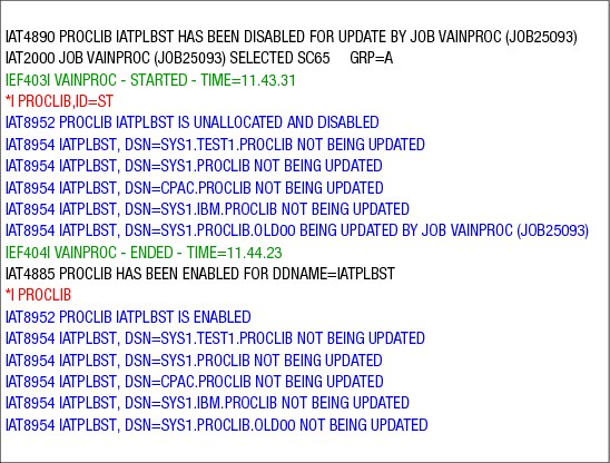
INQUIRY PROCLIB Operator Command
To determine why a job is delayed in C/I service, you can display the status of a procedure library. The *INQUIRY,PROCLIB command displays whether all procedure library concatenations are enabled or disabled, and the job number of the job that is updating a particular data set. The procedure library status can be displayed with the operator command:
*I PROCLIB
The messages show which proclibs are being updated.
In the second command:
*I PROCLIB,ID=ST
ID=ST specifies the procedure library id. If omitted, the status of all procedure libraries will be displayed. Use the two digit suffix of the procedure library when entering a value for procid on the ID= keyword.
..................Content has been hidden....................
You can't read the all page of ebook, please click here login for view all page.