


Main device scheduling (MDS)
JES3 provides a device management facility called the main device scheduler (MDS) that can wholly or partially support the MVS allocation process. The purpose of MDS is to satisfy job resource requirements (the devices, volumes, and data sets needed) before and during job execution, thus allowing execution to proceed without allocation delays. MDS also allows controlled multisystem access to commonly accessible data sets in the JES3 complex environment.
You must choose whether to use the JES3 main device scheduler or use MVS (which controls the job execution) for the entire allocation process as each step begins execution. If you choose MDS, you must then decide whether utilization of MDS is to be partial (set up some jobs, some resources) or total (set up all jobs, all resources).
You need to be aware that if MDS is used to provide resource management, MDS also takes into account the availability of a job's scheduling environment during resource allocation. Scheduling environments and resources are defined by the installation in the Workload Manager (WLM) policy. A scheduling environment is a list of resource names and their required states that are used to ensure that units of work are sent to systems that have the appropriate resources to handle them.
Scheduling environments and resource names reside in the WLM service definition and apply across the entire sysplex. Resource states may have a different setting in each system in the sysplex and are, therefore, system-oriented.
Each element in a scheduling environment consists of the name of a resource and a required state of either ON or OFF, as follows:
•If the required state is ON, then the resource state must be set to ON on an MVS image for the requirement to be satisfied.
•If the required state is OFF, then the resource state must be set to OFF on an MVS image for the requirement to be satisfied.
The SCHENV parameter on a JOB JCL statement specifies the name of the WLM scheduling environment to associate with the job.
8.1 Main device scheduling features
Main device scheduling features
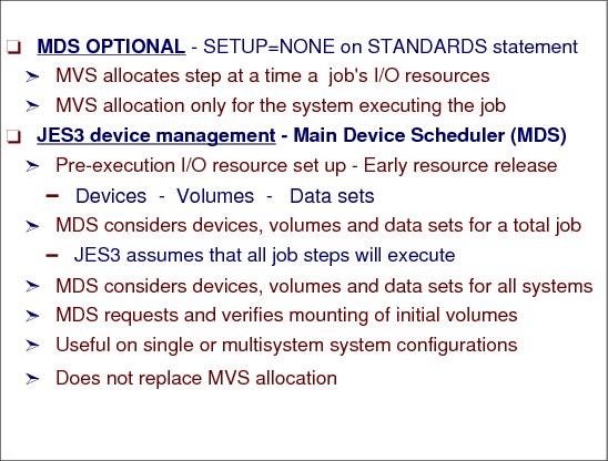
Main device scheduling (MDS) functions are optional and may be bypassed entirely or be applied only for a subset of resources.
MVS allocation
In systems that do not use MDS a job's I/O resource requirements are not known until the job is selected for execution, and a system initiator begins the step allocation process. At each job step, MVS allocation attempts to satisfy the requirements for the step, in contention with every other job step currently executing on the same processor. If the requirements cannot be met, MVS allocation gives the operator the option of canceling the job or allowing it to wait for resources. Thus, in a system that does not use MDS, there may be jobs executing and other jobs in execution waiting for resources.
The jobs waiting in MVS allocation hold critical resources (a system initiator, an address space, data sets, and possibly devices). Holding these resources longer than necessary makes it very difficult for the system programmer to determine how many initiators should be started to keep the system fully used, because at any given time, an unknown number of initiators may be waiting. MDS offers a solution to this problem.
Main device scheduler (MDS) allocation
With MDS, the resources (data sets, devices, and volumes) that a job requires are already set up when the job is passed to MVS for execution. There should never be an idle initiator caused by a job waiting for these resources. Setup occurs while a job is in the JES3 address space, and the only system resource used while the job is waiting is the JES3 queueing space. MDS helps the system make maximum use of devices and allows jobs to run in a minimum amount of time when they are passed to the system for execution. Also, MDS cooperates with the workload management (WLM) component of MVS to ensure that the scheduling environments for jobs are honored.
MDS requests and verifies the mounting of the initial volumes a job requires on each device before the job can be selected for execution (unless deferred volume mounting is specified in the JCL).
Pre-execution setup
Because MDS setup occurs before job execution, JES3 cannot react to processing dependencies that can occur between different jobs and between different steps in the same job. This limitation is particularly important when considering the cataloging and passing of data sets. JES3 cannot determine whether any conditional job steps are skipped as a result of condition code processing. JES3 assumes that all job steps will execute. JES3 also counts the number of I/O devices needed by each step.
The JES3 main device scheduler controls the volume fetching, allocation, mounting, and deallocation of I/O devices associated with job execution on all processors in the complex. MDS allocates I/O resources among competing jobs and release resources as soon as possible after they have been used.
Scheduling environments
If a job is assigned a scheduling environment (for example, the SCHENV= parameter was specified on the JOB statement), the availability of the job's scheduling environment is taken into consideration when determining which systems have the resources for a job. If a job's scheduling environment is not available on a particular system, the job will not run on that system even if the other resources required by the job (e.g. DASD volumes, SMS storage groups) are available on that system. If the scheduling environment later becomes available on a system, the job will be able to run on that system provided that the resources required by the job are also available on that system.
MDS processing is divided into several stages:
•Volume fetch
•System select
•Allocation
•Volume verification
•System verify
•Breakdown
MDS is useful on a global only system or a multi-image complex. It does not replace MVS allocation, but works together with MVS allocation to manage control system resource such as devices, volumes, and data sets.
8.2 MDS benefits

MDS benefits
With MDS, the I/O resources (data sets, devices, and volumes) that a job requires are already set up when the job is passed to MVS for execution. Since I/O resources are available for a job when JES3 passes it for MVS execution, MVS allocation can satisfy the I/O requirements for the steps of the job. The job’s I/O requirements are met and MVS allocation does not need to communicate with the operator and issue allocation recovery messages. JES3 allows all devices, including assignable devices (for example tapes), be online to all MVS systems in the JES3 complex. This provides a way to for better tape utilization because JES3 manages the allocation to tape units prior to execution of the using jobs.
|
Note: MVS supports automatic tape switching (ATS). An automatically switchable tape device can be online to some or all systems that are participating tape sharing within a sysplex. Automatically switchable tapes relieves the operators from keeping track of the online and offline status of tape devices, but MVS allocation may still not be able to meet a job’s tape requirements and may have to issue allocation recovery messages. If the VARY AUTOSWITCH command is issued for a tape device that is online or managed by JES3, the system alerts you to the error.
|
Data set awareness
In a JES3 complex both MVS and JES3 provide data set awareness. Data set awareness ensures that:
•While one job is reading a data set another job does not change that data set
•Only one job at a time uses a sequentially accessed device that is attached to one or more processors
Data set awareness is provided by JES3 in a single or multi-system complex. MDS provides the capability to fence devices for jobs or for a class of jobs. MDS management of resources provides an easier operations for the operator.
MVS data set awareness
Before allocating data sets to a job, MVS enforces data set integrity for MVS-managed data sets. To ensure data set integrity, MVS does not allocate a data set to a job if:
•The job requests non-shared access to an allocated data set
•The job requests shared access to a data set that is allocated as non-shared
MVS does not begin the allocation process until the integrity of all the data sets in the job has been enforced. Once integrity has been established, MVS then begins allocating the resources needed for the job, one step at a time. JCL DD-statement DISP= parameter determines a data set’s integrity requirements.
MVS provides integrity for data sets within a single MVS system or across multiple MVS systems in a sysplex.
JES3 data set awareness
JES3 enforces data set awareness for:
•Data sets that are requested via DD statements that require JES3-managed devices
•Data sets that are requested dynamically that require JES3-managed devices
•Data sets that are SMS-managed, unless SMSSETUP=NO is specified on the SETPARAM statement.
If a job requests a data set via a DD statement, JES3 enforces data set awareness before scheduling the job for execution. For dynamically requested data sets, JES3 enforces data set awareness at the time of the request. To ensure data set awareness, JES3 denies a job's request for a data set if:
•The request is for non-shared access to an allocated data set
•The request is for shared access to a data set that is allocated non-shared
If a job’s allocation request is denied by JES3 and the requested was made using a DD statement, JES3 does not schedule the job for execution at that time. The job must wait until all of the resources it needs are available. If the data set was dynamically requested, JES3 will not let MVS allocate the data set to the job at that time. The job, however, can continue to execute. JES3 also enforces data set awareness for data sets on sequentially accessed devices managed by JES3. Examples of such devices are tape drives. To ensure data set awareness, JES3 allows only one job at a time to use such a device anywhere in the complex.
Device fencing
Device fencing (sometimes called device pooling) for job-class groups can be defined by specifying either the DEVPOOL parameter or the device dedication subparameters in the EXRESC parameter of the GROUP statement. The difference between the two methods of dedication is that devices dedicated via the EXRESC parameter are dedicated when the group is allocated on the processor specified in the EXRESC parameter and DEVPOOL-requested dedication is accomplished when the GROUP is enabled on any processor. The operator use several commands to control the JES3 MDS processes. In general, in a JES3 complex, operators control complex and its systems through JES3 commands - not the individual MVS systems with MVS commands.
8.3 Job active in main scheduler element
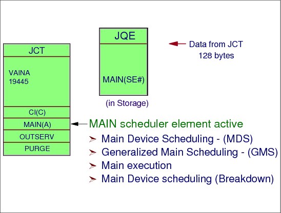
Job active in main scheduler element
The main scheduler element represents the second phase of job processing. Converter/interpreter is the first phase. The converter/interpreter routines construct a job summary table (JST) that lists required data sets and devices, and a job volume table (JVT) that describes the volumes the main device scheduling routines will fetch and allocate. Volumes that are mounted will be verified.
Standard jobs
For standard jobs, main service processing begins when the job segment scheduler reaches the MAIN scheduler element in the job's JCT entry. The MAIN scheduler element represents two DSPs: setup (SETUP) and generalized main scheduling (MAIN). Both of these DSPs are resident and each has a permanent entry on the FCT chain, so the job segment scheduler need not construct the FCT entries.
Main device scheduling (MDS)
The work performed by the SETUP and MAIN DSPs is crucial to JES3 processing. The goals of the SETUP and MAIN DSPs are effective resource utilization and maximum JES3 complex throughput. The processing sequences are:
Initial setup (MDS) processing to prepare I/O resources. The initial setup processing is performed in phases. During the volume fetch phase, messages are sent to tape or DASD library consoles to indicate that a volume is to be fetched.
The allocation phase may be started automatically after the fetch phase, or manually when the operator indicates that the required volumes have been fetched to the work area. If volumes used are always readily available, automatic allocation could be more meaningful because no operator action would be necessary to cause allocation to begin. During the allocation phase, operator messages are issued for pre-mounting of volumes.
During the verification processing phase, checking is performed to ensure that the proper volumes are being mounted on the proper devices. This work is carried on asynchronously as devices become ready. The SETUP DSP maintains “verify counts” relative to individual jobs. The verify count is the number of volumes yet to be mounted for a job. When the verify phase is accomplished, the job will pass from initial setup processing to generalized main scheduling -- at this point, the job can be passed to MVS for execution.
Generalized main scheduling (GMS)
Generalized main scheduling selects and passes a job to an initiator. The job is ready for processing by the MAIN DSP. The main processing of jobs waiting to be selected by MVS is controlled by the installation's tailoring of JES3. When triggered by an MVS initiator's request for a job, the MAIN DSP chooses one jobs to give to the initiator. The selection of one job, in preference to another, is influenced by variables such as:
•The type of work being processed during a shift (test, production, online, batch, etc.)
•Eligibility relationships between jobs and processors based on:
– Job classes
– The number of active initiators for the jobs
– Whether processors are online or offline
– I/O rates of jobs in execution
– Virtual storage requirements relative to the working set size of address spaces given to jobs
•Job priorities, to the extent that the installation wishes to honor priorities
After considering these factors, the MAIN DSP picks our a job, sends information about the job to the requesting initiator, and indicates that the selected job is now “on main”. The MAIN DSP may skip jobs on a given selection pass. Having received the job, the initiator schedules it through all its steps, with JES3 being involved only for items such as:
•Step to step transition
•Opening of SYSIN/SYSOUT data sets
•Dynamic allocation and deallocation of data sets on JES3-managed or SMS-managed devices
•Requests for spool space
MDS breakdown
Breakdown processing to relinquish I/O resources. When a job completes execution under MVS, it is returned to the SETUP DSP for device breakdown processing. At the end of each job step, that is the last to use a device, volume, or data set, the resources are returned to the SETUP DSP for early resource release. Many, if not all, of the job's resources may already have been returned; but in most cases, the devices required for execution of the last step of the job must be returned to JES3 (along with data sets and volumes). Breakdown processing consists of updating control blocks by removing entries or reducing use counts and issuing appropriate “keep” or “retain” operator messages. The purpose, of course, is to make the resources available for use by other jobs that may require them. At this point the job segment scheduler marks the MAIN scheduler element complete and schedules the OUTSERV scheduler element.
8.4 MDS processing phases

MDS processing phases
Each MDS phase has its own queue for jobs waiting to be processed by the phase. The *I,S command, if none of the optional parameters is specified, displays the status of all mains in the complex and a summary of the MDS queues.
MDS FCTs
The FCTs that are involved with the MDS job processing are:
SETUP Main-line processing for volume fetch, job setup, high watermark setup, and explicit setup functions.
VERIFY When a job’s “soft” allocation is successful, MDS allocation issues mount messages for those volumes that need to be mounted on a device. In addition, MDS allocation sends “arm” requests to the VERIFY FCT (IATLVVR) on the selected processor to prepare the device for volume mounting.
DYNAL Main-line processing for dynamic allocation-fast path.
Fetch phase
Volume fetch, the first phase of MDS, is performed for all jobs entering MDS. This phase determines the volumes required by the job and, if necessary, instructs the operator to get the volumes from the library. This phase also eliminates those mains on which the job cannot run. During fetch processing, JES3 builds volume entries and issues messages for volumes that have no entries in the Resident Volume Allocation Table (SETVOL - IATYVLM) which contains the volume serial number for each reference to a device managed by MDS. Volume fetch messages are selected optionally by specifying FETCH=YES on the JES3 SETPARAM initialization statement. When you select the fetch option, JES3 issues volume fetch messages to indicate which volumes are required for specific jobs to execute. Volumes already mounted require no fetch processing, and volumes that have been fetched but not mounted get action-coded messages. Device types other than tape or disk do not require operator action. If you do not specify the volume fetch option, jobs go directly into the system select stage of MDS if the job requires SMS-managed resources, or into allocation if the job does not require SMS-managed resources.
System select phase
The system select phase of MDS is performed when a job requires one or more resources managed by the storage management subsystem (SMS). If the job does not require any SMS-managed resources, the job proceeds directly to MDS allocation. JES3 is not aware of the availability or connectivity of SMS-managed resources. If a job requires SMS-managed resources, JES3 requests SMS to determine the availability of those resources and to determine which mains have access to those resources. If JES3 determines that one or more mains have access to all of the required resources, the job proceeds into the allocation phase. If no mains have access to all of the required resources, JES3 invokes user exit IATUX61 (Cancel Jobs Going on the MDS Error Queue) to determine whether the job should be placed on the MDS error queue or canceled. If you do not implement IATUX61, MDS places the job on the MDS error queue where an operator must either restart the job or cancel it using a *RESTART,SETUP or *CANCEL,SETUP command respectively.
Allocate phase
This phase of MDS uses allocation algorithms to provide required devices for jobs. When allocation is successful, JES3 issues mount request messages for all required volumes except:
•Deferred mount requests - where no mount is as yet requested but the device that the volume is to be mounted on is allocated to the user.
•Permanently resident volumes - where the mount is unnecessary
•Multi-volume mount - where only the first volume of a multi-volume data set is mounted; secondary volumes are not mounted until required.
The ALLOCATE= keyword on the JES3 SETPARAM initialization statement controls how jobs are processed during MDS allocation. If ALLOCATE=AUTO (default) is specified, MDS sends incoming jobs directly into allocation unless a job requires SMS-managed resources. If a job requires SMS-managed resources, the job is first sent to system select before proceeding into the allocation phase. If ALLOCATE=MANUAL is specified, the operator must issue the *S S command for each job requiring volumes to be fetched before the job can go through MDS allocation. Jobs that require volumes to be fetched are kept in the MDS WAITVOL queue. At the start of the MDS allocation phase, a job is selected from the ALLOCATE queue. MDS examines the job's resource requirements and attempts to allocate the required devices, volumes, and data sets. For SMS-managed data set resource, only the data set is allocated. JES3 is not aware of SMS-managed volumes and devices. When MDS initially tries to set up a job, it records the total device, volume, and data set requirements for the job. When allocation fails because needed devices, volumes, or data sets are unavailable, the job is queued for another attempt. However, MDS sends jobs back to the system select phase of MDS if all of the following conditions occur:
1. A job requires both SMS-managed resources and MDS-managed resources.
2. The list of eligible mains determined by the system select phase do not have access to both the MDS-managed resources and the SMS-managed resources.
3. One or more mains not in the original list of mains has access to all of the required resources, and the SMS-managed resources are temporarily unavailable to those mains.
|
Note: The generalized main scheduling (GMS) resources (job class groups and job classes) must be available before MDS resource allocation is attempted.
|
Verify phase
JES3 issues messages that instruct you to mount a job's required volumes. You can implement installation exit IATUX62 (Verify a Mount Request) to validate, accept, or override JES3's decision about whether a volume has been successfully mounted. JES3 invokes IATUX62 after the volume verification phase of MDS. The VERIFY function automatically obtains the volume serial number, label status, and other information for MDS after you mount the job's required volumes. You can install installation exit IATUX25 (Examine/Modify Volume Serial Number) to validate any nonstandard labels used in the installation. When all volumes are properly mounted, the job is ready for execution. However, if the job requires SMS-managed resources, it proceeds to the system verify phase of MDS before execution. Device types other than tape or disk do not require operator action.
System verify phase
The system verify phase of MDS is performed when a job requires SMS-managed resources. This phase of MDS ensures that all of the SMS-managed resources required by a job are still available before execution. For example, if a job spends too much time in MDS allocation or a long period of time elapses between a mount request and the actual mounting of a required volume, one or more of the SMS-managed resources could become unavailable. If the status of SMS-managed resources required by the job has not changed, that is, all of the required SMS-managed resources are still available and are accessible by the eligible main(s), the job can proceed into execution. However, if SMS-managed resources required by a job are no longer available, JES3 generates a new list of systems where SMS managed resources are available. JES3 then checks this list against the following:
•All jobs to see if they can access the SMS and JES3 resources
•Batch jobs to see if the class and group are available on the systems where SMS managed resources are available.
•Batch jobs with associated scheduling environments to see if there are any systems where the scheduling environment and the SMS managed resources are available.
If there are no systems where all of the above resources are available, the job is sent to the breakdown phase where MDS deallocates resources held by the job. MDS then sends the job back to the system select phase where MDS retries allocation.
Breakdown phase
JES3 automatically performs the breakdown phase of MDS when a job no longer needs a resource such as a data set, volume, or device. The resource is then available for use by other jobs. MDS does not deallocate SMS-managed resources other than data sets because JES3 is not aware of SMS-managed devices and volumes.
JES3 issues messages that indicate whether volumes should be retained for use by other jobs or demounted. The RETAIN and KEEP messages issued by MVS allocation apply only to the resources used within one job, while the RETAIN and KEEP messages issued by MDS consider volume usage by all jobs currently in the system that use JES3-managed or jointly-managed devices. In the event that both MVS and JES3 issue KEEP or RETAIN messages regarding a specific volume, the JES3 messages take priority.
8.5 SETPARAM statement

SETPARAM statement
Use the SETPARAM initialization statement to specify parameters that the JES3 main device scheduler (MDS) and the DYNAL DSP uses in allocation, mounting, and deallocation of devices for jobs run on all mains. The SETNAME and DEVICE statements are used with the SETPARAM statements. SETNAME and DEVICE identify the devices to be managed by MDS. SETPARAM also indicates how MDS is to manage devices.
|
Note: For the DAFETCH, MDSLOG and TAFETCH parameters, the default of 97 is the routing code equivalent of JES3 destination class S1.
|
ADDRSORT= Specifies the order in which JES3 MDS allocates devices.
NO - Indicates that devices within a device type are to be allocated in the same order as the DEVICE statements are placed in the initialization stream.
YES - Indicates that devices within a device type are to be allocated by the order of their device numbers, that is, 188, 189, 18A.
ALLOCATE= Specifies whether automatic allocation of a job is to immediately follow MDS volume fetch. This parameter is ignored for jobs that reference only premounted volumes. The FETCH parameter specified may override the ALLOCATE parameter.
MANUAL - Indicates that all jobs are to be suspended following volume fetch until the operator causes them to continue. Note that ALLOCATE=MANUAL is ignored if FETCH=NO is indicated; ALLOCATE=AUTO is assumed instead.
AUTO - Specifies that MDS will automatically attempt allocation of resources for all eligible jobs. If a job requires SMS-managed resources and you specify ALLOCATE=AUTO, MDS sends the job through the system select phase before allocation to determine which mains have access to the required SMS-managed resources. Note that ALLOCATE=AUTO is assumed (ALLOCATE=MANUAL is ignored) if FETCH=NO is specified.
DAFETCH= Specifies the routing information for direct-access volume fetch messages. msgdest Specifies a SETUP-related console destination class. Direct-access volume fetch messages are issued with the routing code equivalent of this destination class.
NONE - Indicates that volume fetch messages are not to be issued.
97 - Indicates that volume fetch messages are to be issued with routing code 97; messages also are recorded on the hard-copy log. Note that this parameter is ignored if FETCH=NO is also specified. 97 is the routing code equivalent of JES3 destination class S1.
nnn - Specifies an MVS routing code from 1 to 28, or 41 to 128. Routing codes 29 through 40 are reserved for IBM's use and will be ignored if specified.
DEFERCT= Specifies whether jobs requiring deferred mounts (whether explicitly requested through JCL, or implicitly requested because of using tape library devices) should be included in the CLASS/SELECT SDEPTH counts. The default is DEFERCT=NO.
DSN= Specifies the number of characters (0 to 44) of the data set name to be included in MDS volume fetch, mount, and breakdown messages. This parameter is used for message formatting. If DSN=0 is specified, then the data set name is omitted from these MDS messages.
FETCH= Indicates whether MDS is to issue volume fetch messages. Note that the FETCH parameter can override the ALLOCATE parameter.
NO - Specifies that MDS is not to issue volume fetch messages. If FETCH=NO is specified, ALLOCATE=MANUAL is overridden (and ALLOCATE=AUTO assumed); MDS automatically attempts to set up jobs.
YES - Indicates that MDS is to issue volume fetch messages.
MDSLOG= Specifies the routing information for all non-action messages (that is, job LOGON and error messages).
msgdest - Specifies a SETUP-related console destination. Non-action messages are issued with the routing code of the destination class.
97 - Indicates that non-action messages are issued with routing code 97.
nnn - Specifies an MVS routing code from 1 to 28, or 41 to 128. Routing codes 29 through 40 are reserved for IBM's use and is ignored if specified.
MTJESMSG= Specifies whether you want FETCH, ALLOCATION, and BREAKDOWN messages for mountable devices to appear in the JESMSGLG data set.
FETCH - Specifies that you want fetch messages for mountable devices written into the JESMSGLG data set.
ALLOC - Specifies that you want allocation messages for mountable devices written into the JESMSGLG data set.
BREAKDWN - Specifies that you want breakdown messages for mountable devices written into the JESMSGLG data set.
ALL - Specifies that you want fetch, allocation, and breakdown messages for mountable devices written into the JESMSGLG data set.
NONE - Specifies that you do not want fetch, allocation, or breakdown messages for mountable devices written into the JESMSGLG data set.
|
Note: When you use the default (ALLOC and BREAKDWN), allocation and breakdown messages for mountable devices are written into the JESMSGLG data set.
|
FETCH - Specifies that you want fetch messages for permanently resident or reserved DASD written into the JESMSGLG data set.
ALLOC - Specifies that you want allocation messages for permanently resident or reserved DASD written into the JESMSGLG data set. If this value is specified, an allocation message will be written for all non-mountable requests in addition to permanently resident DASD.
ALL - Specifies that you want both fetch and allocation messages for permanently resident or reserved DASD and allocation messages for all other devices written into the JESMSGLG data set.
NONE - Specifies that you do not want fetch or allocation messages for permanently resident or reserved DASD written into the JESMSGLG data set.
REMOUNT= Specifies the number of times that an operator can retry to correct volume mount errors for a job before the devices for the job are released and allocation is restarted. The value of nnn specifies the number of retries allowed, from 0 to 255. For example, if REMOUNT=1 is specified, the operator can make two attempts to mount the volume--the original mount request and one retry request.
SDEPZERO= Indicates whether jobs that require a tape mount, but are in a CLASS, are defined as SDEPTH=0, should wait on the MDS allocate queue, the default, or be sent to the MDS error queue.
SMSSETUP= Specifies whether JES3 manages SMS data sets.
NO - Indicates that SMS data sets are not to be managed by JES3.
YES - Indicates that SMS data sets are to be managed by JES3.
If you specify an incorrect subparameter or do not specify the SMSSETUP= parameter, MVS determines whether JES3 manages SMS data sets or not.
TAFETCH= Specifies the routing information for tape volume fetch messages. The first operand specifies the routing information for specific (nonscratch) volume requests. The second operand specifies the routing information for scratch volume requests.
msgdest - Specifies a SETUP-related console destination class. Tape volume (scratch or nonscratch) fetch messages are issued with the routing code equivalent of this destination class.
NONE - indicates that volume fetch messages are not to be issued.
97 - Indicates that volume fetch messages are to be issued with routing code 97; messages also are recorded on the hard-copy log. Note that this parameter is ignored if FETCH=NO is also specified.
nnn - Specifies an MVS routing code from 1 to 28, or 41 to 128.
ALWIO= The ALWIO parameter specifies the current number of asynchronous I/O requests which can be processed concurrently. This value must be a number from 1 to the value specified in the MAXIO parameter. The value specified in the ALWIO parameter must be less than or equal to the value specified in the MAXIO parameter.
This parameter can be displayed through the *I S,ALWIO=nn command, and modified through the *F S,ALWIO=nn operator command.
MAXIO= The MAXIO parameter specifies the maximum number of asynchronous I/O requests that can be processed concurrently. Storage is obtained for the number of requests specified here. Note that an increase of one in this parameter results in a 76-byte increase in storage used. This parameter can only be changed when performing a warm start or cold start. The value specified in the MAXIO parameter may be a number from 1 to 99. The default value is 25. The value specified in the MAXIO parameter must be greater than or equal to the value specified in the ALWIO parameter.
SETPARAM example
In the following example, volume fetch messages are issued with the routing code equivalent of the destination classes specified:
S7 Nonscratch tape volume fetch messages.
S10 Scratch tape fetch messages.
S9 Direct-access volume fetch messages.
Also, MDS messages would identify the first 15 characters of the data set names. All nonaction messages would go to console destination S1. If necessary, one retry to mount any volume would be allowed. Allocation would occur automatically following volume fetch. Allocation order for devices would be by the order of their device numbers, as follows:
SETPARAM,FETCH=YES,TAFETCH=(S7,S10),DAFETCH=S9,DSN=15
8.6 MDS processing queues

MDS processing queues
The MDS processing queues can be displayed by using the operator commands shown in the figure under each queue.
The SETUP DSP’s data CSECT, IATMDDA mapped by IATYMDS macro, contains the MDS chain pointers.
MDCHAINS DS 0F START OF MDS CHAINS
MDFETCHQ DC F'0' START OF FETCH CHAIN
MDVOLWTQ DC F'0' START OF VOLUME WAIT CHAIN
MDALLOCQ DC F'0' START OF ALLOCATE CHAIN
MDVOLUAQ DC F'0' START OF UNAVAILABLE CHAIN
MDVERFYQ DC F'0' START OF VERIFY CHAIN
MDERRORQ DC F'0' START OF ERROR CHAIN
MDBRKDNQ DC F'0' START OF BREAKDOWN CHAIN
MDRSTRTQ DC F'0' START OF RESTART CHAIN
MDYNALOQ DC F'0' START OF DYNAMIC ALLOC CHAIN
SETUP FCT await flags
The SETUP FCT waits on the MDSECF flag byte for posts. The SETUP FCT posts are:
MDSECF EQU MDSECFAR,1 MDS ECF
MDSBK EQU X'80' BREAKDOWN POST BIT
MDSMSG EQU X'40' MESSAGE POST BIT
MDSAL EQU X'20' ALLOC POST BIT(SEE MDSALECF)
MDSVFY EQU X'10' VERIFY POST BIT
MDSRST EQU X'08' RESTART POST BIT
MDSFE EQU X'04' FETCH POST BIT
MDSASYNC EQU X'02' ASYNCRONOUS PROCESSING REQ'D
MDSIPOST EQU X'01' INTERNAL PROCESSING REQ'D
SETUP FCT posted
In general, the SETUP FCT is posted whenever there is a change of the MDS managed resources, the status of the jobs running under the MAIN scheduler element. Examples of the events that cause SETUP to be posted:
•JSS adds new jobs
•SETUP queues a job to new subchain
•Main processor comes online or goes offline
•GMS job class group, job class, or scheduling environment status change
•WLM policy change
•SMS resources, storage groups and volumes, change status
•Jobs status is changed by operator (hold, release, cancel, class change)
•Device availability status is changed
•Jobs in MVS execution request dynamic allocation/unallocation
•Jobs in MVS execution terminate
The MDS processing queues can be displayed with the *INQUIRY S the operator command.
8.7 JES3/DFSMS communication

JES3/DFSMS communication
JES3 SMS support provides complex-wide data set awareness for DFSMS-managed data sets through subsystem interface communication with DFSMS, Main processor and DFSMS resource availability are determined for scheduling jobs into execution using these interface calls.
JES3 and DFSMS communicate required to:
•Make sure that catalog locates are done on a processor with access to the required catalogs.
•Make sure that jobs requiring DFSMS resources execute on processors to which the resources are accessible and available.
•Provide complex-wide data set awareness for all DFSMS managed requests (even for new, non-specific requests).
•Remove JES3 awareness of units and volumes for DFSMS managed data sets. (One of the DFSMS objectives is to remove user awareness of the physical storage.)
System Select is a phase of MDS processing and calls DFSMS System Select to access the JES3 spool through the SPAF interface. DFSMS System Select is invoked prior to MDS allocation to determine the availability and processor connectivity of a job's DFSMS managed resources. This frees JES3 from having to know about the status of DFSMS resources, and prevents MDS from allocating and mounting devices before the status of DFSMS resources is known. If all the resources are available, the job continues into MDS; otherwise, the job waits until the required resources become available.
System Verify is a phase of MDS processing and calls DFSMS System Select to access the JES3 spool through the SPAF interface. DFSMS System Select is also invoked after MDS verify to determine whether the status of DFSMS resources has changed since the last call to DFSMS System Select was made. If the status has changed and there is now a conflict in the systems required to access the DFSMS resources, the job is failed. If the status of the job and scheduling information has not changed, the job is placed on the Generalized Main Scheduling (GMS) queue. If the information from the SPAF file has changed, the job is recycled through MDS.
The IDAX is invoked by the MVS Interpreter at the end of interpretation to analyze the JCL and to construct SWBs for required DFSMS information. When the C/I is running under JES3, it indicates to the IDAX that the caller wants system scheduling information. IDAX collects scheduling information for new data sets to be allocated by this job and saves it in the scheduling information SPAF file. The Scheduler JCL Facility (SJF) is used to scan the SWA blocks, and IDAX creates SWBs for new DFSMS managed data sets. The Automatic Class Selection (ACS) routines and the installation ACS user exits are invoked at this point. The data class and storage class is selected at this time for new DFSMS managed data sets. IDAX catalog processing determines all of the catalogs required by a job and divides them into two categories: DFSMS managed user catalogs, and JES3 managed user catalogs. Information about the DFSMS managed user catalogs is written to the job's SPAF file for later use in MDS.
In addition, if the job has DFSMS managed user catalogs, PLCO is invoked to determine the processors that have access to the required catalogs. This information is returned to JES3 and used to determine where locates should be scheduled. Information about the non-DFSMS managed user catalogs is also returned to JES3. JES3 then adds those user catalogs that require JES3 managed devices to the job's setup requirements.
DFSMS PLCO is invoked through an SSI Call from IDAX. There are two calls to DFSMS PLCO; from DFSMS IDAX and from POSTSCAN. The PLCO is invoked by the DFSMS IDAX during MVS interpretation to determine the availability and processor connectivity of all DFSMS managed catalogs required by the job. DFSMS returns to JES3 a list of processors that can currently access all the DFSMS managed catalogs required by the job. This list is used by JES3 to determine which main processors can be used for locate processing. If one or more catalogs is unavailable, the job is rescheduled for locate processing when it becomes available.
From POSTSCAN, DFSMS PLCO is invoked prior to JES3 locate processing for jobs that have been rescheduled to determine whether the SMS-managed catalogs required by the job are available. Access to the SPAF files is through the resource status token passed from the DFSMS PLCO call. The main processors eligible for locate processing are determined and the job's main mask is updated. DFSMS PLCO is performed for the first time for all jobs during MVS interpretation.
DFSMS Catalog Services is invoked during locate processing, instead of SVC 26, for all existing data sets when DFSMS is active. Locates are required for all existing data sets to determine whether they are DFSMS managed, even if VOL=SER= is present on DD statement. If VOL=REF= is present on a DD statement, the DFSMS VOLREF Service is invoked.
|
Note: JES3 locate processing calls DFSMS Catalog Services at the end of locate processing for cleanup and at this time writes the scheduling information, collected by DFSMS Catalog and VOLREF Services, and writes it to the spool through SPAF. DFSMS does not have to be active on local processors for locates to take place there.
|
DFSMS VOLREF Services are invoked during locate processing, instead of SVC 26, for each data set that contains a volume reference to a cataloged data set. DFSMS VOLREF Services determines whether the data set referenced by a VOL=REF= parameter is DFSMS managed. Note that VOL=REF= now maps to the same storage group for an DFSMS managed data set, not necessarily to the same volume. DFSMS VOLREF Services also collects information about the job's resource requirements.
SPAF is used by DFSMS to access resource information on spool. For DFSMS, this includes the DFSMS scheduling information spool data set and the DFSMS job information spool data set. The DFSMS scheduling information spool data set is a spool-resident data set that contains scheduling information for all the new and old DFSMS managed data sets referenced in a job, as well as scheduling information for the catalogs required by the job. The DFSMS job information spool data set is a spool-resident data set that contains job related information used during locate processing to determine to which storage group a migrated DFSMS managed data set may be recalled. The SPAF is invoked by SSI and uses USAM to read from and write to the data set specified by caller. SPAF offers read only access through the USAM interfaces.
|
Note: The systems in the JES3 complex must be defined in the DFSMS control data set for proper JES3 DFSM operation.
|
8.8 JSS scheduling of MAIN SE

JSS scheduling of MAIN SE
The JES3 job segment scheduler (IAGRJS) schedules a job’s MAIN scheduler element by obtaining an RQ, appropriately setting RQINDEX, and calling RQTAADD to add the RQ to the RQINDEX chain. The RQTAADD macro posts the appropriate DSP.
IATXGRQ macro service obtains an RQ from a RESQUEUE cellpool. The type of RQ is based on DSP dictionary entry provided. If a JCT address is also provided, the RQ is initialized with data from the JCT.
RQINDEX parameter
This parameter specifies the chain where the entry is placed. If "name" is coded, the name specified must be one of the terms defined for field RQINDEX in the IATYRSQ macro. If omitted, the index in the entry is used.
The INDEX parameter on the RQTAADD macro specifies the chain where the entry is placed. These fields are defined in the IATYRSQ macro. During the time a job exists in the system, the job will exist on many of these resqueue indexes. The RQINDEX value is then an indicator of where the job is currently processing. The RQ index values used for processing of jobs through both MDS, MAIN, and OUTSERV scheduler elements are:
RQNOSUB NO SUBCHAIN EXISTS
RQFSSCI ACTIVE IN CI IN AN FSS ADDRESS SPACE
RQPSCBAT AWAITING POSTSCAN (BATCH)
RQPSCDSL AWAITING POSTSCAN (DEMSEL)
RQFETCH AWAITING VOLUME FETCH
RQVOLWT AWAITING START SETUP
RQSYSSEL AWAITING/ACTIVE IN MDS SYSTEM SELECT PROCESSING
RQALLOC AWAITING RESOURCE ALLOCATION
RQVOLUAV AWAITING UNAVAILABLE VOL(S)
RQVERIFY AWAITING VOLUME MOUNTS
RQSYSVER AWAITING/ACTIVE IN MDS SYSTEM VERIFY PROCESSING
RQERROR ERROR DURING MDS PROCESSING
RQSELECT AWAITING SELECTION ON MAIN
RQONMAIN SCHEDULED ON MAIN
RQWTR AWAITING WTR OUTPUT (ASP)
RQTERM AWAITING MAIN TERMINATION (ASP)
RQBRKDWN AWAITING BREAKDOWN
RQRESTRT AWAITING MDS RESTART PROC.
RQDONE MAIN AND MDS PROC. COMPLETE
RQOUTPT AWAITING OUTPUT SERVICE
RQOUTQUE AWAITING OUTPUT SERVICE WTR
RQOSWAIT AWAITING RSVD SERVICES
RQCMPLT OUTPUT SERVICE COMPLETE
RQDEMSEL AWAITING SELECTION ON MAIN (DEMAND SELECT JOB)
RQEFWAIT ENDING FUNCTION RQ WAITING FOR I/O COMPLETION
RQEFBAD ENDING FUNCTION RQ NOT PROCESSED
8.9 RESQUEUE chaining

RESQUEUE chaining
When the job segment scheduler (JSS) is dispatched, it examines JQEs to find an eligible job so it can schedule a DSP. Part of the processing is construction of an FCT entry when the DSP being scheduled is not represented by a resident FCT entry. In addition to constructing and enqueuing an FCT entry (if necessary), the job segment scheduler always builds a resident queue element (RQ or RESQUEUE). The RQ is built after the job is scheduled and it thus becomes the basis for DSP processing.
The RQ is a large control block containing status flags, job information fields, and queuing pointers. RQs last only for the life of a scheduler element. Pointers in the RQ allow JES3 DSPs working on behalf of a job to find all the other job-related information kept by JES3.
The RQ represents a scheduling chain within a given DSP. It contains a summary of the information the DSP needs to accomplish its function, plus additional information. The JSS builds the RQ from information in the JCT entry. Pointers from the JCT entry to the job's other single-record files (SRFs) are extracted and placed into the RQ. The RQ contains spool information for the job that is executing and holds even more information about the job than the JCT entry.
MAIN scheduler element processing
During the MAIN SE processing a job may be active on several DSPs and several DSPs can be active with one job at the same time. To facilitate this, an RQ control block includes several chain fields:
•RQNEXT -- All RQs are chained together through this field.
•RQGRPCHN -- CI/MDS/MAIN/OUTSERV/JSS subchain.
•RQWTRCHN -- WRITER OUTPUT subchain.
•RQSPNCH -- SPINOFF OUTPUT subchain.
•RQDYACHN -- DYNAMIC ALLOCATION subchain
Anchor chain pointers
The TVT table contains the following RQ chain anchors:
•RQTOP -- Start of RQ chain. All RQs are on this chain
•SPORQTOP -- Start of SPINOFF RQ chain
•OSSWAIT -- OUTPUT SERVICE WAIT chain
•OSSRQTOP -- Start of RQ OUTPUT chain
•Some functions have their RQ chain anchors in the DSP’s data csect. These data csects are pointed from the TVT table. For example MDS data csect (IATMDDA) is pointed from MDSPARM field in TVT.
RQ chaining
RQs are chained to proper queues using macro services. IATGRRQ module contains the routines to service the following macros:
•The RQTAADD macro adds an RQ to the RESQUEUE chain and subchain.
•The RQTAPUT macro moves an from one chain to another or changes the priority within a chain.
•The RQTADEL macro deletes an RQ from a RESQUEUE chain and subchain.
8.10 Job chains in MDS processing queues
Job chains in MDS processing queues
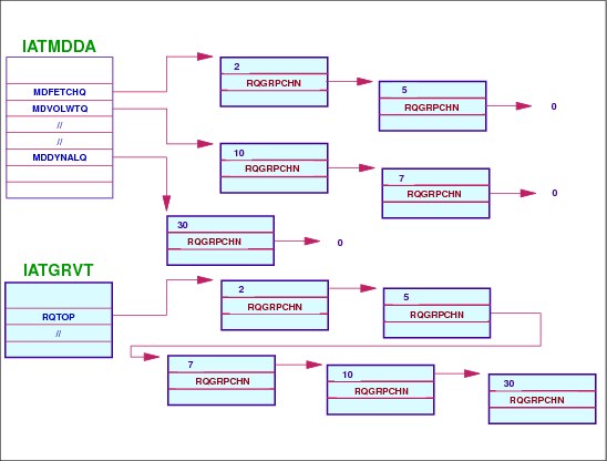
The SETUP DSP’s data CSECT (IATMDDA) is pointed from MDSPARM field in TVT. The IATMDDA control block contains commonly used data areas and flags referenced by all MDS modules. The MDS RQ subchain anchors are in the IATMDDA data CSECT:
MDFETCHQ START OF FETCH CHAIN
MDVOLWTQ START OF VOLUME WAIT CHAIN
MDALLOCQ START OF ALLOCATE CHAIN
MDVOLUAQ START OF UNAVAILABLE CHAIN
MDVERFYQ START OF VERIFY CHAIN
MDERRORQ START OF ERROR CHAIN
MDBRKDNQ START OF BREAKDOWN CHAIN
MDRSTRTQ START OF RESTART CHAIN
MDYNALOQ START OF DYNAMIC ALLOC CHAIN
Active job in MAIN SE
When a job is active under the MAIN scheduler element in SETUP DSP, the placement of a job (represented by an RQ) on a MDS resqueue subchain is based on the RQINDEX value that represents the current MDS processing phase. In a very busy system, there are many jobs in each of these chains as shown in the visual as an example. MDS processing under the SETUP FCT searches each chain to schedule the job to the next RQINDEX value when it is then placed at the end of the next RQINDEX chain.
RQTOP chain
All RQ entries exist on a separate chain entry called RQTOP that exists in the TVTABLE control block (module IATGRVT).
RQINDEX chain pointers in IATMDDDA
The MDS RQINDEX values are:
RQFETCH AWAITING VOLUME FETCH
RQVOLWT AWAITING START SETUP
RQALLOC AWAITING RESOURCE ALLOCATION
RQVOLUAV AWAITING UNAVAILABLE VOL(S)
RQVERIFY AWAITING VOLUME MOUNTS
RQERROR ERROR DURING MDS PROCESSING
RQSELECT AWAITING SELECTION ON MAIN
RQBRKDWN AWAITING BREAKDOWN
RQRESTRT AWAITING MDS RESTART PROC.
8.11 A job’s MAIN scheduler element status

A job’s MAIN scheduler element status
The following commands *I J, *I P, and *I Q produce the IAT8674 message the indicates current status of jobs for that command.
*I J= command
On a job inquiry command, *I J=, when the MAIN scheduler element is the active one, the status shown in the MAIN scheduler element is ready to be processed or is being processed for the job. If no DSP is running yet, only MAIN appears in the message. Otherwise, the status indicates where the job is in relationship to the functions of main service processing.
FETCH The job is waiting for volume fetch processing.
WAITVOL The job is waiting for *S setup processing.
SYSTEM SELECT The job is on the system select queue.
ALLOCATE The job is waiting for resources to be allocated.
VOL UNAVAIL The job is waiting for an unavailable volume.
VERIFY The job is waiting for volumes to be mounted.
SYSTEM VERIFY The job is on the system verify queue.
MDS ERROR The job is waiting for an operator decision. (MDS error queue)
GMS SELECT The job is waiting to be selected for processing on the main.
EXECUTING The job is in execution.
BREAKDOWN The job is waiting for its resources to be deallocated (MDS breakdown).
MDS RESTART The job is waiting for MDS restart processing.
MAIN COMPLETE The job is complete on main.
OUTSERV WAIT The job is in the process of being rescheduled.
DEMAND SELECT The job is a demand-select job that is waiting to be selected for main.
I/O WAIT The ending function RESQUEUE is waiting for I/O to complete.
ENDFUNC ERROR Error - the ending function RESQUEUE was not processed.
DSP ABEND The MAIN scheduler element ended by JES3 failsoft processing.
*I S command
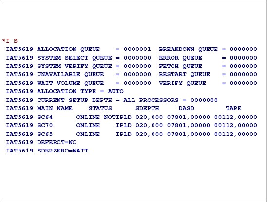
The *I S command to displays the status of jobs currently in setup or the status of volumes and data sets controlled by MDS.
*I S
IAT5619 ALLOCATION QUEUE = 0000001 BREAKDOWN QUEUE = 0000000
IAT5619 SYSTEM SELECT QUEUE = 0000000 ERROR QUEUE = 0000000
IAT5619 SYSTEM VERIFY QUEUE = 0000000 FETCH QUEUE = 0000000
IAT5619 UNAVAILABLE QUEUE = 0000000 RESTART QUEUE = 0000000
IAT5619 WAIT VOLUME QUEUE = 0000000 VERIFY QUEUE = 0000000
IAT5619 ALLOCATION TYPE = AUTO
IAT5619 CURRENT SETUP DEPTH - ALL PROCESSORS = 0000000
IAT5619 MAIN NAME STATUS SDEPTH DASD TAPE
IAT5619 SC64 ONLINE NOTIPLD 020,000 05997,00000 00064,00000
IAT5619 SC70 ONLINE NOTIPLD 020,000 05997,00000 00064,00000
IAT5619 SC65 ONLINE IPLD 020,000 05997,00000 00064,00000
*I B command
The *I B command to displays the number of jobs backlogged for each JES3 function (DSP), for a job class, for a job class group, for a service class, for a terminal group, or for a main or all mains.
*I B
IAT8688 FUNCTION ACTIVE WAITING
IAT8688 CI 00000000 00000004
IAT8688 INTRDR 00000002 00000000
IAT8688 ISDRVR 00000000 00000002
IAT8688 MAIN 00000063 00000004
IAT8688 MONITOR 00000001 00000000
IAT8688 NJECONS 00000001 00000000
IAT8688 NJERDR 00000001 00000000
IAT8688 OUTSERV 00001412 00000000
IAT8688 SNARJP 00000001 00000000
IAT8688 TCP 00000001 00000000
IAT8688 WTR 00000001 00000000
IAT8619 INQUIRY ON BACKLOG COMPLETE
*I G command
Use the *I G command to obtain the status of GMS components of JES3 and to display the name of the spool partition assigned for a specific main or all mains. A main's spool partition contains the spool data for each job that runs on that main unless other partitions were specifically assigned for the job's job class, SYSOUT data, or in the job's //*MAIN control statement.
Display the status of class A on all systems.
*I,G,ALL,C,A
IAT8934 CLASS - A - STATUS=ON - GRP=JES3TEST - SY2
IAT8934 CLASS - A - STATUS=ON - GRP=JES3TEST - SY1
IAT8934 CLASS - A - STATUS=ON - GRP=JES3TEST - SY3
8.12 MDS operator commands

MDS operator commands
The operator has many commands to determine the MDS options and to look at each of the MDS processing queues. The initialization options may be displayed and then modified.
*I S command
The *I S command to display the status of jobs currently in setup, counts of jobs in various MDS queues, the status of main processors, or the status of volumes and data sets controlled by MDS.
*F S command
The *F S command allows to:
•Make a volume unavailable for JES3 setup processing
•Make a volume available for JES3 setup processing
•Keep a real direct access volume mounted on a designated device. This command is also valid for devices containing SMS-managed volumes
•Unload a volume mounted on a designated device
•Specify automatic or manual allocation of JES3-managed devices. This command overrides the specification established by the ALLOCATE parameter on the SETPARAM initialization statement.
•Specify whether or not to include jobs that require only deferred mounts in the setup depth counts (SDEPTH).
•Determine if volumes required and presumed mounted for a designated job have been mounted. Use this command if all of the volumes have been mounted, but the expected responses, via JES3 volume verification, have not been recognized.
•Change the current number of asynchronous I/O requests that can be processed simultaneously.
•Specify whether scratch and specific tape requests and scratch requests of different media types are separated during high watermark processing.
•Specify whether or not all initial verify response messages are written to the hardcopy message log (MLOG).
*S, *R, *C setup commands
For jobs active in the MDS processing queues, the operator may issue start, restart, or cancel to the job.
The *S S command -- If manual allocation was specified during JES3 initialization or with the *F,S,AL=M command, the *S S command to allows a job to proceed to allocation processing. The *S S command is not required when automatic allocation was specified during JES3 initialization or by the *F S,AL=A command.
The *R S command to returns a job to the allocation stage (after volume fetch). The *RESTART,S command is used when a volume or device requested or needed by the job is unavailable. Generally, the *R S command can be used to return any job in the main device scheduling (MDS) processing to the MDS allocate queue. If a job is MVS restarting and the *R S command is issued to restart that job, the job becomes eligible to run on any main rather than only on the main where it was originally selected.
The *C S command to cancels a job currently being processed by main device scheduling (MDS).
8.13 MDS commands
MDS commands
The *I S command to display the status of jobs currently in setup, counts of jobs in various MDS queues, the status of main processors, or the status of volumes and data sets controlled by MDS.
The *I S command can also be used to display information for main processors, but only if SETUP is active in the complex. IBM suggests using the *I MAIN= command for this purpose instead of *I S as it does not depend on SETUP and displays more comprehensive information relevant to main processors.
DEFERCT=YES | NO
The current value of the DEFERCT option. This indicates whether or not JES3 is to include jobs that require only deferred mounts in the CLASS/SELECT SDEPTH counts.
SDEPZERO=WAIT | ERROR
The current value of the SDEPZERO parameter. This indicates whether jobs that require a tape mount, but are of a class that does not permit them, for example SDEPTH=0, should wait, for example, for a class or SDEPTH change, or be treated as if in error.
8.14 JES3 device concepts

JES3 device concepts
Before JES3 can manage the use of an I/O device, the device must be attached to a main processor and it must be defined in the JES3 initialization stream. Devices are defined to JES3 with a DEVICE initialization statement. The DEVICE statement is used to define a device that JES3 can use as follows:
•To satisfy its own functions (JES3 device or global device).
•To satisfy the needs of a job (execution device).
•As a JES3 device or as an execution device (shared device).
Global devices
JES3 devices must be attached to the global processor. The only exception is a device driven by an output writer functional subsystem (FSS), which you may define as a JES3 device and attach to the global processor or a local processor. The JUNIT keyword is used to define the device that can be used by JES3 functions such as DSPs.
Execution devices
The DEVICE statement specifies device characteristics and tells JES3 how to use that device. The XUNIT parameter specifies the characteristics of a device attached to one or more mains (LPARs). If a device is shared between two or more mains, all four subparameters are specified for each main to which the device is attached. If a device is shared between channels of the same main, the SYSGEN primary address should be the only subparameter indicated.
Global and execution devices
Devices can be defined as both a global used device and an execution device. If JES3 functions are using the device, it is not available as an execution device and visa versa.
Defining devices
The ways to define a device to a JES3 system are:
•You can specify that JES3 is to use a device to satisfy JES3 functions, such as DSP requests, input processing, and output processing. This is called a JES3 device (aka support unit).
•You can specify that JES3 may allocate a device to MVS to execute user jobs. This is called an execution device.
•An execution device that is defined to JES3 and MVS as permanently resident or reserved is called a jointly-managed device.
•You can specify that JES3 can use the device as either a JES3 device or as an execution device. This is called a shared device.
JES3 devices must be attached to the global processor. The only exception is a device driven by an output writer functional subsystem (FSS), which you may define as a JES3 device and attach to the global processor or a local processor.
You can define as JES3 devices: main processors, network lines, printers, card punches, card readers, remote terminals, and tape drives.
8.15 JES3 task structure for MDS

JES3 MDS tasks
The MDSSRS FCT, like SETUP, resides permanently in the JES3 global address space along with an MDS master subtask attached by IATMDAT and several MDS subtasks attached by IATMDMT. The number of MDS subtasks changes, corresponding to the amount of work there is to do. The FCT is responsible for setting up and passing work to available subtasks. Each subtask is represented by an MDS control table used for communication between the FCT and the subtask.
Each LPAR has a locate master task and multiple locate subtasks. The locate master task is responsible for attaching new locate subtasks. The locate subtasks are responsible for performing the actual locates and each subtask is represented by a locate control table (LCT). The locate FCT maintains the locate master task and subtasks on that LPAR and is responsible for the following activities:
•Initializing new subtasks
•Terminating subtasks that are no longer needed
•Terminating subtasks for jobs that have been cancelled
•Cleaning up subtasks that have abended
The locate FCT on each LPAR is responsible for determining when to attach and detach locate subtasks. If the average number of waiting requests is greater than the number of locate subtasks attached, the locate FCT attaches more subtasks if a job requires one. The number that can be attached is one half of the difference between the average number of waiting requests and the number of subtasks attached.
8.16 JES3 MDS initialization statements

MDS initialization statements
Main device scheduling initialization includes processing MDS-related initialization statements such as DEVICE, SETACC, SETNAME, SETPARAM, SETRES and DYNALDSN, building MDS-related tables, loading the resident MDS processing modules, and calling IATMDAT to attach the MDS master task which attaches the MDS subtasks.
DEVICE statement (Tape and DASD)
The DEVICE statement is used to define I/O devices to JES3. To define an execution device, specify the XTYPE and XUNIT parameters on the DEVICE statement. When any execution device is initialized, JES3 varies the device online or offline to MVS and JES3 based on the XUNIT parameter specification. You can attach execution devices to the global processor or to any local processor.
SETACC statement
Use the SETACC initialization statement to identify those mains that normally have access to a permanently resident direct-access volume. The SETACC statement identifies the location of a volume on the uninitialized mains in a JES3 complex. SETACC prevents JES3 from setting up a job that needs the mounted volume until the main is initialized. When all mains are initialized or the volume is found, the SETACC definition is no longer used and normal JES3 management of the volume and device occurs. The devices on which the volumes reside are defined on a DEVICE statement with an XTYPE parameter and PR subparameter.
SETNAME statement
Use the SETNAME initialization statement to specify all user-assigned names and device type names associated with MDS-managed devices.
SETPARAM statement
Use the SETPARAM initialization statement to specify parameters that the JES3 main device scheduler (MDS) and the DYNAL DSP uses in allocation, mounting, and deallocation of devices for jobs run on all mains. The SETNAME and DEVICE statements are used with the SETPARAM statements. SETNAME and DEVICE identify the devices to be managed by MDS. SETPARAM also indicates how MDS is to manage devices.
SETRES statement
The SETRES statement identifies frequently used direct-access volumes which are not permanently resident. The SETRES statement specifies volumes which may be on devices at main initialization time. When a specified volume is found to be present on an MDS-managed, removable, direct-access device during main initialization, the volume is considered mounted by MDS, without a MOUNT command being necessary.
DYNALDSN statement
Use the DYNALDSN statement to specify which data sets on permanently resident or reserved DASD volumes require data set awareness protection when the data set is dynamically allocated.
8.17 DEVICE initialization statement
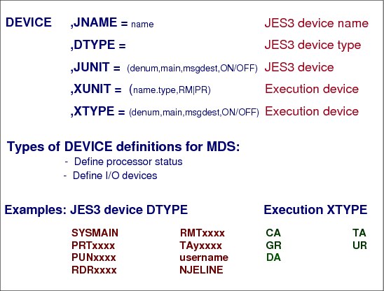
DEVICE initialization statement
To define a JES3 device, specify the DTYPE, JNAME, and JUNIT parameters on the DEVICE statement. If applicable, you should also specify the DGROUP parameter and any printer or punch parameters. One DEVICE statement must be coded for each I/O device that JES3 uses or manages. Define devices as follows:
•To define a device as a shared device, specify the DTYPE, JNAME, and JUNIT parameters on the DEVICE statement for that device.
•To define an execution device, specify only the XTYPE and XUNIT parameters on the DEVICE statement for that device.
•To define a device as a shared device, specify the DTYPE, JNAME, JUNIT, XTYPE, and XUNIT parameters on the DEVICE statement for that device.
Execution devices
To define an execution device, specify the XTYPE and XUNIT parameters on the DEVICE statement. When any execution device is initialized, JES3 varies the device online or offline to MVS as well as to JES3 based on the XUNIT parameter specification. You can attach execution devices to the global processor or to any local processor.
DTYPE parameter
The DTYPE parameter specifies a device type being defined to JES3:
SYSMAIN This type DEVICE statement defines the initial status for a main.
NJELINE This type of DEVICE statement defines a BSC line or a CTC connection to another node in a NJE network.
PRTxxxxx Identifies a locally-attached printer. Specify PRTAFP1 for AFP1 printers. An AFP1 printer can be either channel attached or non-channel attached.
PUNxxxx Identifies a locally-attached punch.
RDRxxxx Identifies a locally-attached reader.
RMTxxxx Identifies a remote terminal (described by an RJPTERM or RJPWS statement). For SNA RJP printers, specify RMTPRINT. For SNA RJP punches, specify RMTPUNCH.
TAxxxxx Identifies a tape device.
username Indicates a device type which is associated with a user DSP.
XTYPE parameter
The XTYPE=(name,devtype) parameter on a DEVICE statement specifies the characteristics of the JES3-managed or jointly managed device as it is used by jobs in execution. It must precede the XUNIT parameter, which is required if XTYPE is specified.
The name subparameter of the XTYPE parameter specifies a 1- to 8-character name that defines a device that can be referenced. It should match the name specified in the XTYPE parameter on a SETNAME initialization statement.
The values of devtype subparameter of the XTYPE parameter are:
•CA -- Specifies that the device is cartridge tape.
•TA -- Specifies that the device is reel tape.
•GR -- Specifies that the device is graphic.
•UR -- Specifies that the device is unit record.
•DA -- Specifies that the device is direct access. DASD devices can have attribute removable volumes (RM) whose mounting is to be controlled by MDS or MVS permanently resident volumes (PR).
|
Note: Devices within a specific XTYPE should have compatible characteristics. For a SNA-attached AFP printer, XTYPE is not a valid parameter.
|
XUNIT parameter
The XUNIT=(/devnums,main,msgdest,ON|OFF,....) parameter on a DEVICE statement specifies the characteristics of a device attached to one or more mains. If a device is shared between two or more mains, all four subparameters are to be specified for each main to which the device is attached unless the *ALL main name is used. complex. When *ALL is used, no other group of devnum,main,msgdest,OFF|ON can be used on the XUNIT parameter of this DEVICE initialization statement, and the values specified for devnum,main,msgdest,OFF|ON are the same for all mains.
Types of DEVICE definitions
The DEVICE initialization statements is used to define:
•Processor Status -- This form of the optional DEVICE statement defines the initial status of mains in a JES3 complex. If omitted, the processor in question is initialized online to every processor in the complex. For more information on defining mains. For example:
DEVICE,DTYPE=SYSMAIN,JNAME=SC64,JUNIT=(,SC64,,OFF,,SC70,,ON,,SC65,,ON)
DEVICE,DTYPE=SYSMAIN,JNAME=SC64,JUNIT=(,*ALL)
•I/O Devices -- This form of the DEVICE statement defines a device that JES3 can use to satisfy its own functions (JES3 device), to satisfy the needs of a job (execution device), or as a JES3 device or as an execution device (shared device).
8.18 Defining tape devices

Defining tape devices
At any one time, a single tape device can be used only by one processor. The processor assignment hardware feature prevents a tape drive from being used by another host processors in shared configuration. If no assign commands have been issued to a tape drive, any attached host processor may use that drive. Drive assign and unassign commands are issued by the MVS operating system when a tape drive is brought online or is taken offline. In non-JES3 multisystem complex operators must coordinate to which system tape drives are online.
A tape drive assigned to more than one processor is called multisystem assigned. JES3 uses multisystem assign when it brings tape drives online. Thus all tape drives can be simultaneously online to all mains in the JES3 complex. MDS keeps complex wide track of the defined tape drives’ allocation status and lets only those jobs go to execution that have all tape allocation requested satisfied. If a job’s all allocated tape drives have connectivity to several mains in the JES3 complex, the job can be sent to execution to any of these processors.
|
Note: The MVS automatic tape switching (ATS) implements the tape sharing within a sysplex without using multisystem assign. When a tape device is defined as automatically switchable, the device must be in a offline state. The VARY device,AUTOSWITCH,ON operator command marks a tape device autoswitchable. The device (UCB) is set online, but it is not assigned. The device will be assigned during MVS allocation for the system where a job requests tape drives. When the job unallocates the tape drives, MVS unassigns the devices.
|
8.19 Defining DASD devices

Defining DASD devices
DASD devices are sharable. Multiple jobs may access the same device while executing.
Data set awareness
The JES3 main device scheduler fetch processing scans jobs’ JST entries and builds a SETVOL table entry (IATYSET) for each of the volumes required by the job. For SMS-managed data sets, JES3 is not concerned with and does not know about the volumes where the data sets reside. However, the fetch routine still creates a dummy SETVOL table entry since MDS is responsible for complex wide data set awareness. The fetch routine creates the SETVOL entry using a dummy volser. This allows the SMS-managed data sets to be distributed over a number of SETVOL entries. If a volume is not mounted, the fetch routine issues a fetch message to the operator. The SETVOL table entries point to the SETDSN entries (IATYDS) for the data sets on the volume.
JES3 enforces data set awareness for:
•Data sets that are requested through DD statements that require JES3-managed devices
•Data sets that are requested dynamically that require JES3-managed devices
•JES3-managed sequentially accessed devices that are attached to one or more processors
•Data sets that are SMS-managed, unless SMSSETUP-NO is specified on the SETPARAM statement.
– JES3 is not aware of units for SMS-managed data sets:
*I S DE=VAINI.SMS.MANAGED.DATA
IAT5674 DATASET IS SMS MANAGED
IAT5610 AL=0000001 DSN=VAINI.SMS.MANAGED.DATA
IAT5612 JOB VAINI (JOB24889) AL=YES S-VAINI.SMS.MANAGED.DATA
*I S DE=VAINI.NONSMS.DATA
IAT5606 SER=VAINIJ DA J=0000022 AL=0000022 ONADEV
IAT5610 AL=0000001 DSN=VAINI.NONSMS.DATA
IAT5612 JOB VAINI (JOB24889) AL=YES S-VAINIJ S-VAINI.NONSMS.DATA
The JES3 data set awareness processing is based on the SETVOL/SETDSN table structure and the serialization is by data set name on a volume. Since MVS and JES3 data set awareness processing are using different convention for serialization, JES3 may allow a job, allocating a data set with a specific volume request, to go to MVS execution when a data set name is already serialized in the MVS terms.
MVS serialization
In a sysplex MVS serializes sysplex wide (ENQ scope SYSTEMS) the access to data sets. During a job’s first step initialization MVS allocation serializes access to all data sets referenced by the job. If the a data set is allocated with DISP=SHR, the serialization is for shared access, otherwise (DISP=OLD/MOD/NEW) the access is exclusive. The MVS data set serialization is by data set name only.
SMS-managed data sets
JES3 manages all requests for SMS-managed data sets unless SMSSETUP=NO is specified on the SETPARAM initialization statement. However, JES3 is not aware of specific units for SMS-managed data sets. JES3 treats requests for these data sets as single requests and sends them through dynamic allocation - fast path. All dynamic allocation requests for SMS-managed data sets that require more than one SIOT, such as GDG-all requests, will be sent through MDS for processing instead of dynamic allocation - fast path.
8.20 Generic and esoteric I/O device names
Generic and esoteric I/O device names
You use the Hardware Configuration Definition (HCD) program to add, delete, or change JES3 defined devices. These can be JES3 global devices (JUNIT), execution devices (XUNIT), or shared devices (both JUNIT and XUNIT). When making these changes, be careful not to introduce subgeneric splits, define devices to JES3 but not to MVS, or define devices as one device type to JES3 but a different device type to MVS.
If you make a mistake, JES3 will tolerate the error and initialize (if there are no other errors with higher impact); however, you should correct the error and perform a hot start with refresh at your earliest convenience.
An eligible device table (EDT) is an installation-defined and named representation of the I/O devices that are eligible for allocation. Using HCD, you define EDT information in an IODF. At IPL or dynamic configuration, information in the IODF and UIMs is used to build the EDT.
Esoteric device groups
The execution devices defined to JES3 should be grouped using esoteric names. An esoteric (or esoteric device group) is an installation-defined and named grouping of I/O devices of usually the same device group. EDTs define the esoteric and generic relationship of these devices. The name you assign to an esoteric can be used in the JCL DD statement. The job then allocates a device from that group instead of a specific device number or generic device group.
Generic names are provided by the unit information modules (UIMs) included in hardware configuration definition (HCD). Generic (or generic device type) is an MVS-defined grouping of devices with similar characteristics. Every generic has a generic name that is used for device allocation in the JCL DD statement. MVS interprets this name as “take any device in that group”.
To request allocation of a device from an esoteric device group, specify the esoteric name on the UNIT= parameter of a JCL DD statement. (In JCL terminology, an esoteric name is called a group name.)
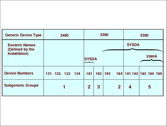
Subgeneric groups
MVS allocation divides generic device types into subgeneric groups. The subgeneric groups allows MVS allocation to serialize a subset of units within a generic name. For example, using the figure, if 3390A is requested, MVS allocation needs to serialize only subgeneric group 5 rather than all 3390 devices. As a result, more than one allocation can process the same generic device type, as long as the allocations require different subgeneric groups within that generic.
The guidelines by which MVS determines subgeneric groups are:
•If an esoteric name (for example, 3390A) includes only a subset of the units in a generic name, that subset is a subgeneric group. (For 3390A in the visual, units 193, 194, and 195 belong to a subgeneric group.)
•If an esoteric (for example, SYSDA) includes different generic device types, the units in each generic name belong to different subgeneric groups. (For SYSDA in the visual, units 181, 183, and 184 belong to one subgeneric group; units 191 and 192 belong to another subgeneric group; and units 193, 194, and 195 belong to a third group.)
•The units not contained in the intersection of a generic group and its new subgeneric groups constitute a subgeneric group. (For SYSDA and 3380 in the visual, unit 182 comprises a new subgeneric group.)
If one unit of a subgeneric group is defined to JES3, all units of the subgeneric group must be defined to JES3. (For subgeneric group 2 in the visual, if unit 183 is assigned to JES3, units 181 and 184 must also be assigned to JES3.) Thus, a subgeneric group cannot have system-managed devices mixed with JES3-managed and jointly managed devices.
8.21 Grouping I/O devices
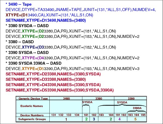
Grouping I/O devices
When the devices assigned to an esoteric or generic name are to be managed by JES3, one or more of the subgeneric groups that constitute that name must be defined to JES3 via DEVICE initialization statements. For example, SYSDA in the visual is composed of subgeneric groups 2, 4, and 5. For SYSDA devices to be managed by JES3, at least one of the subgeneric groups, 2, 4, and 5 must be defined to JES3. For SYSDA devices in subgeneric group 4 (191 and 192), or all the devices in subgeneric group 2 (181, 183, and 184), all the devices must be defined to SYSDA on the NAMES parameter of the SETNAME initialization statement. Thus, an esoteric or generic name may comprise JES3-managed, jointly managed, and system-managed devices. Since a subgeneric group can belong to different generic or esoteric names, it is possible that the subgeneric group could be managed both by JES3 and MVS. For example, 3390A in the visual might be MVS-managed, whereas subgeneric group 5 might be JES3-managed. If a device is being managed both by JES3 and by MVS, MVS does not allocate to any device that does not have a permanently resident volume (jointly managed). Sample JES3 DEVICE statements for each subgeneric:
* 3490 -- Tape
DEVICE,DTYPE=TA33490,JNAME=TAPE,JUNIT=(131,*ALL,S1,OFF),NUMDEV=4
XTYPE=(D13490,CA),XUNIT=(131,*ALL,S1,ON)
SETNAME,XTYPE=D13490,NAMES=(3480)
* 3380 SYSDA -- DASD
DEVICE,XTYPE=(D23380,DA,PR),XUNIT=(181,*ALL,S1,ON)
DEVICE,XTYPE=(D23380,DA,PR),XUNIT=(183,*ALL,S1,ON),NUMDEV=2
* 3380 -- DASD
DEVICE,XTYPE=(D33380,DA,PR),XUNIT=(182,*ALL,S1,ON)
* 3390 SYSDA -- DASD
DEVICE,XTYPE=(D43390,DA,PR),XUNIT=(191,*ALL,S1,ON),NUMDEV=2
* 3390 SYSDA 3390A -- DASD
DEVICE,XTYPE=(D53390,DA,PR),XUNIT=(193,*ALL,S1,ON),NUMDEV=3
SETNAME,XTYPE=D23380,NAMES=(3380,SYSDA)
SETNAME,XTYPE=D33380,NAMES=(3380)
SETNAME,XTYPE=D43390,NAMES=(3390,SYSDA)
SETNAME,XTYPE=D53390,NAMES=(3390,SYSDA,3390A)
XTYPE parameter
In the sample, the two first characters of the XTYPE name are used to refer to subgeneric groups. For example, the XTYPE name for tape units is D13490, where the two first characters (D1) are used to reference subgeneric group 1 on the visual and for the rest of name is used the generic device type.
The XTYPE=(name,type,PM|PR) parameter of the DEVICE statement specifies the characteristics of the JES3-managed or jointly managed device as it is used by jobs in execution. It must precede the XUNIT parameter, which is required if XTYPE is specified.
Where:
name - specifies a name that defines a device that can be referenced. It should match the name specified in the XTYPE parameter on a SETNAME initialization statement.
type:
• CA Specifies that the device is cartridge tape.
• TA Specifies that the device is reel tape.
• GR Specifies that the device is graphic.
• DA Specifies that the device is direct access.
• UR Specifies that the device is unit record.
RM - Specifies that the device will contain removable volumes whose mounting is to be controlled by MDS.
PR - Specifies that the device will contain MVS permanently resident volumes.
SETNAME initialization statement
The SETNAME initialization statement specifies all user-assigned names and device type names associated with MDS-managed devices. The NAMES parameter identifies all names (user-assigned and device type) used to refer to the device defined in the associated DEVICE statement. NAMES= indicates what names are used to specify devices in the UNIT parameter of DD statements.
8.22 Using *ALL in XUNIT and JUNIT definitions

Using *ALL in XUNIT and JUNIT parameter
The XUNIT= and JUNIT= parameter of the DEVICE statement has the same syntax:
(devnum,main,msgdest,OFF|ON)
main Specifies a processor which can use this device as a JES3 global device when that main is global. This name must be the same name as that defined in the NAME parameter on a MAINPROC initialization statement. The device must be attached to this main at the address specified by /devnum or devnum.
Alternatively, a main name of *ALL can be used. Using *ALL indicates that all processors in the complex are eligible to use this device as a JES3 global device when the processor is the global. When *ALL is used, other group of devnum,main,msgdest,OFF|ON cannot be used on the JUNIT parameter of this DEVICE initialization statement, and the values specified for devnum,main,msgdest,OFF|ON are the same for all mains.
Specifying *ALL
Using *ALL on a device is particularly useful if you will be adding MAINPROCs later, as you do not need to add the new main name to any DEVICE statement that uses *ALL. The following rules apply when using *ALL:
•Mixing *ALL and system names within the same JUNIT or XUNIT is not allowed.
•*ALL must appear only once within the same JUNIT or XUNIT.
•If *ALL is used on the JUNIT and the device has both a JUNIT and an XUNIT, *ALL also must be used on the XUNIT. If *ALL is used on the XUNIT, the JUNIT can list processors, but the use of *ALL on the JUNIT is suggested.
8.23 Defining a range of devices - NUMDEV parameter

Defining a range of devices
NUMDEV=nnnn parameter on DEVICE statement specifies the number of devices to be defined by this DEVICE statement, starting with the specified JUNIT. For example, if a DEVICE statement defines a JUNIT of 140 and NUMDEV=32, the statement defines 32 devices with device numbers of 140 through 15F. The NUMDEV parameter requires at least one JUNIT with a device number (that is, a device number other than NONE).
When NUMDEV is used, the JNAME parameter specifies a prefix rather than a complete JNAME. A four digit device number is built based on the JUNIT and NUMDEV and concatenated with the prefix to form a complete JNAME. For example, if the JUNIT is 140, the specified JNAME is LINE, and NUMDEV=32, the statement will define 32 JNAMEs, LINE0140 through LINE015F.
If the JUNIT combines mains with different device numbers (for example, JUNIT=(140,SY1,,ON,8C0,SY2,,ON), the first specification is used to build the JNAMEs (140 is this case).
If the JUNIT combines mains with device numbers and NONE (for example, JUNIT=(NONE,SY1,,ON,8C0,SY2,,ON), the first group with an actual device number is used to build the JNAMEs (8C0 in this case).
|
Note: The NUMDEV parameter requires at least one JUNIT or XUNIT with a device number. For example, NUMDEV is not valid on a DTYPE=SYSMAIN or a VTAM-attached FSS printer.
|
Referenced JNAME
If the device is a JES3 global device, the JNAME parameter specifies a prefix rather than a complete JNAME. A four digit device number is built based on the JUNIT and NUMDEV and concatenated with the prefix to form a complete JNAME. For example, if the JUNIT=3A0, the specified JNAME is TAPE, and NUMDEV=32, the statement will define 32 JNAMEs of TAPE03A0 through TAPE03BF. Because of converting JNAME this way, omitting NUMDEV for JES3 global devices is not the same as specifying NUMDEV=1.
If the JUNIT combines mains with different device numbers, for example, JUNIT=(3A0,SY1,,ON,9C0,SY2,,ON), the first specification is used to build the JNAMEs (3A0 in this case).
If the JUNIT combines mains with device numbers and NONE, for example, JUNIT=(NONE,SY1,,ON,9C0,SY2,,ON), the first group with an actual device number is used to build the JNAMEs (9C0 in this case).
Since the JUNIT part of the JNAME is padded with 0's if it is a three digit device, be careful to use the correct JNAME if you reference a JNAME on any other initialization statement (for example, FSSDEF or SYSOUT).
NUMDEV rules
When using NUMDEV for a global device, the JNAME specifies a prefix. JES3 combines the prefix with each JUNIT in the requested range as a four digit device number to construct JNAMEs for all devices defined by this statement. In the following example, the JNAMEs for the printers defined by the statement are AFPP0803, AFPP0804, AFPP0805, AFPP0806, and AFPP0807. The prefix cannot exceed four characters.
DEVICE,DTYPE=PRTAFP1,JNAME=AFPP,FSSNAME=FSSAFP1,
JUNIT=(803,SY1,S1,OFF,803,SY2,S2,ON),XTYPE=(PRTAFP1,UR),
XUNIT=(803,SY1,S1,OFF,803,SY2,S2,OFF),WS=(D),
DGROUP=ARM1,PM=(LINE,PAGE),MODE=FSS,NUMDEV=5
NUMDEV cannot be zero, and cannot cause the range to exceed FFFF. If NUMDEV is 1, the JNAME specifies a prefix just as it does for larger values.
If you define an FSS managed printer without using the FSSNAME= parameter, the FSS name is the same as the constructed JNAME. If you use the FSSNAME= parameter, the FSS name is the specified FSSNAME.
If a JNAME of a device defined using the NUMDEV statement is referenced anywhere else in the initialization stream (for example, on the DEST= keyword of a SYSOUT statetement) make sure that the referenced name is the same as the constructed name.
At least one XUNIT or channel attached JUNIT is required. For example, NUMDEV cannot be used on a DEVICE statement for a 3820 printer. JNAME cannot be specified if JUNIT is not specified.
If the device is defined with different device numbers on different processors, each processor gets a range of the same number of devices starting with the specified unit. The unit used to build the JNAME is the first channel attached unit that appears in the JUNIT parameter.
8.24 JES3 device tables

JES3 device tables
JES3 MDS device allocation uses five tables: SYSUNITS, SETUNITS, SETNAME, SETDSN, and SETVOL.
JES3 GETUNIT macro
Module IATGRGU services requests for JES3 global device allocation (GETUNIT) and unallocation (PUTUNIT). GETUNIT/PUTUNIT service uses the SYSUNITS table which provides information on the current status of global devices. JSS issues the macro when scheduling JES3 DSPs that require devices during their execution.
SUPUNITS table
The SUPUNITS table (IATYSUP) is created for JES3 devices (DTYPE, JNAME, and JUNIT parameters on the DEVICE statement) and provides information on the current JES3 status of the global devices.
The SUPUNITS table entries identify the devices that are allocated to the JES3 global. These devices are used by JES3's support services (i.e. ‘readers, printers, tape units, RJP lines and networking lines).
The SUPUNITs table is initialized only on the global main and contains entries for each defined JES3 device that names the current global processor in the JUNIT specification.
SYSUNITS table
The SYSUNITS table (IATYSYS) contains JES3 managed device allocation status for the entire JES3 complex. SYSUNITS table entries include a pointer to the SETUNITS entry for each main processor, SETVOL entry address of current volume, masks of mains to which the device is attached and online, and the current allocation status.
Separate entries exist for the same device when it is shared by two or more mains.
SETUNIT tables
The SETUNITS tables (IATYSET) contains an entry for each JES3 managed devices attached to a main. Each defined main has its own SETUNITS table. The SETUNIT table contains information representing device status on a particular main processor. The status information includes the RQ address of the job using the device.
The SETUNITS table is generated to contain control information for all devices attached to a main that can be set up by MDS from the global main. The data for the table originates from the XUNIT and XTYPE parameters of the DEVICE initialization statement.
SETVOL and SETDSN tables
The SETVOL (IATYVLM) table is generated to maintain information regarding all known volumes requirements for jobs in the system and to track the status of currently mounted volumes. The source of data includes DD statements, automatic verification (by JES3 VERIFY), and operator commands.
The information kept in the SETVOL table entry includes pointers to the SETDSN table.
SETDSN table is created to represent all data sets allocated to volumes. It is used in conjunction with the SETVOL table to ascertain when a volume is no longer in use.
SETDSN table entries (IATYDSN) are used by MDS to control the serialization and shareability of a particular data set.
SETNAMES table
The SETNAMES table (IATYNAM) correlates the device types specified by the JCL UNIT parameter and the devices satisfying that designation.
The SETNAMES table is generated from parameters on the SETNAME statements. The data is used to identify a name than can be used in the UNIT parameter of a DD statement for a device represented in a DEVICE initialization statement.
|
Note: A JES3 formatted dump includes SUPUNITS, SUPUNITS, SUPUNITS, SETVOL, SETDSN and SETNAMES information.
|
8.25 SETNAME initialization statement

SETNAME Initialization Statement
The JES3 MDS algorithm uses the information specified on the SETNAME statement when searching for the proper device to be allocated for a DD request.
If a DD request is to be handled by JES3, the value (excluding the specific device number) specified in the UNIT parameter of the DD statement must also be specified in the NAMES parameter of the SETNAME statement. If the request specifies a device number in the UNIT parameter, the device number must also be specified in the XUNIT parameter of the DEVICE statement.
SETNAME statement parameters
SETNAME,XTYPE=devicetype,NAMES=(name,...)
The following applies to SETNAME parameters:
•The XTYPE parameter indicates the name which matches the first operand in the XTYPE parameter on a DEVICE statement. The XTYPE parameter associates this statement with a specific device definition indicated on a DEVICE statement. Devices within a specific XTYPE should have compatible characteristics.
•The NAMES parameter identifies all names (user-assigned and device type) used to refer to the device defined in the associated DEVICE statement. The NAMES parameter indicates what names are used to specify devices in the UNIT parameter of any DD statements. Note that device type names must be included if allocation of cataloged data sets that reside on these device types is done by JES3 even though the devices are not directly referred to in the UNIT parameter of a DD statement.
•POOLNAMS parameter specifies the name(s) that may be used only for dedicating devices to job class groups or dependent job control jobs. The pool names specified may be used in the DEVPOOL parameter of the GROUP statement and/or the //*NET statement. These names may not be used in the UNIT parameter of the DD statement.
|
Note: The MVS device generic names must be included data sets are to be allocated using cataloged information. This even though direct reference to the devices using the generic names are not made in the UNIT parameter of allocating DD statements.
There must be a SETNAME statement for the IBM generated esoteric names SYSALLDA, SYS3480R, and SYS348XR in the initialization deck if these values are to be coded or defaulted for allocations which are to be JES3 manages.
If a dynamic allocation is made for a time-sharing user and a UNIT parameter is not included in the DD statement, the UNIT parameter is obtained from the time-sharing user attribute data set (UADS). If the UADS does not contain a UNIT parameter, or if the user is not a time-sharing user, an MVS default of SYSALLDA (that is, all direct access devices) is assumed.
It is recommended that a default UNIT parameter value be defined in the UADS or RACF user profile’s TSO segment, in the ALLOCxx parmlib member, and that all dynamic allocations specify a UNIT parameter. Otherwise, if JES3 is to manage the dynamic allocations that do not have a UNIT parameter, the MVS default UNIT value (SYSALLDA) must be included in SETNAMES for all DA device types.
|
JCL example
The JCL DD statement in the figure requests UNIT=SYSDA. This UNIT=SYSDA must then appear on a SETNAME statement in the initialization stream. The SETNAME statements that have this UNIT= have a corresponding XTYPE that will indicate which devices are eligible to satisfy the DD request.
In other words, if a DD request is to be handled by JES3, the value (excluding the specific device number) specified in the UNIT parameter of the DD statement must also be specified in the NAMES parameter of the SETNAME statement. If the request specifies a device number in the UNIT parameter, the device number must also be specified in the XUNIT parameter of the DEVICE statement.
8.26 HWSNAME initialization statement
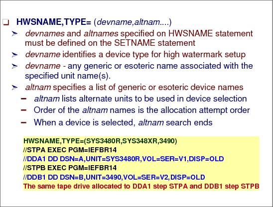
HWSNAME initialization statement
The HWSNAME statement is used to define, to JES3, all names by which users can reference a given device type to enable high watermark setup (HWS) processing. The statement identifies the characteristics of each device name for the specific JES3 complex. This statement can be used to define which device names are subsets of other device names. In general, the fewer the number of alternate names, the more restrictive the device name being defined. This ensures that initial allocation for devices that are reused from step to step is the most restrictive device. It also ensures that attempts to override passed or cataloged unit names are processed correctly. Non-HWS users are encouraged to supply HWSNAME information to take advantage of this function. The HWSNAME statement follows:
HWSNAME,TYPE=(devname,altnam....)
TYPE= specifies the name(s) of a device type that is valid for high watermark setup.
devname Specifies any user-supplied or IBM-supplied group name associated with the specified unit name(s). The identifies a device type valid for high watermark setup.
altnam Specifies a list of valid user-supplied or IBM-supplied device names. These are alternate units to be used in device selection. The order of these names is the order in which allocation is attempted; when a device is selected, no search for a later alternate is made.
altnam specification
Special care must be taken when specifying alternate names. The alternate device must be compatible, for MVS allocation purposes, with the device specified by the devname subparameter. Thus, you may not specify a 3390 DASD as an alternate name for a 3330 DASD, and you may not specify 3330 as an alternate name for 3390. Similarly, you may not specify a 2400-series tape drive as an alternate for a 3400-series tape drive. You may, however, specify a 3400-series tape drive as an alternate for a 2400-series tape drive.
HWS benefits
High watermark setup, as defined on the HWSNAME initialization statement, reduces the number of devices JES3 reserves for a job. To determine how many devices of a particular type to reserve for a job, JES3 considers the needs of each of the job's steps. In this way, JES3 determines which step needs the greatest number of devices of that type; JES3 then reserves that many devices of that type for the job. JES3 repeats this process for each device type the job needs. As a result, high watermark setup can cause premounting of all mountable volumes. Volume unloading and remounting may occur for both private and public volumes, even when RETAIN has been specified on the applicable DD statement.
When high watermark setup is used, as in job setup, devices, volumes, and data sets are returned to JES3 for use by other jobs as soon as the DD statement is deallocated in the last step using the resources. When it is advantageous to use fewer devices for a job, high watermark setup is preferable to job setup.
STANDARDS statement specification
High watermark setup is used when SETUP=THWS (for tapes only), SETUP=DHWS (for disks only), or SETUP=HWS (for tapes, disks, graphics, and unit-record devices). If the SETUP parameter is not specified on a //*MAIN statement, then high watermark setup is used only when SETUP=THWS, SETUP=DHWS, or SETUP=HWS is specified on the STANDARDS initialization statement or when the specified setup is overridden by installation exit IATUX08.
Cataloged data sets may reference devices that are valid for use during HWS. You define these devices using the HWSNAME initialization statement. If a cataloged data set references a device that has been removed as a HWS device (that is, the device has been removed from the HWSNAME initialization statement), that data set is no longer eligible for HWS processing.
The STANDARDS statement specifications are:
SETUP=JOB |NONE | DHWS | THWS | HWS
8.27 MDS initialization parameters

MDS initialization parameters
The STANDARDS initialization statement specifies default values for information not provided on other JES3 initialization statements. It also provides standards to be applied to all jobs entering the system.
The SETPARAM initialization statement specifies parameters that the JES3 main device scheduler (MDS) and the DYNAL DSP uses in allocation, mounting, and deallocation of devices for jobs run on all mains. The SETNAME and DEVICE statements are used with the SETPARAM statements. SETNAME and DEVICE identify the devices to be managed by MDS. SETPARAM also indicates how MDS is to manage devices.
SETUP parameter of the STANDARDS initialization statement
The SETUP= parameter of the STANDARDS initialization statement indicates the system standard for allocation of devices identified by the NAME parameter of SETNAME statement(s). The SETUP= parameter specifies the type of setup processing, such as job setup, tape high watermark setup, or disk high watermark setup. This parameter also provides the default for the SETUP parameter on the //*MAIN JES3 statement and also, SETUP=NONE overrides the SETUP parameter on the //*MAIN statement.
NONE Specifies that no pre-execution setup is to occur. All devices are allocated, mounted, and deallocated by MVS; the SETPARAM statement is ignored. The SETUNITS and SETNAME tables are created even though MDS processing does not occur.
JOB Specifies that pre-execution setup is to occur by job for those devices (indicated in the UNIT parameter of DD statements for the job) which are identified in the SETNAME statement. All devices for the job are allocated to the job from first step to last. This type of setup improves job turnaround time at the expense of overall device usage efficiency.
DHWS Specifies that high watermark setup is to occur for only MVS direct-access units identified in the SETNAME statement. The direct-access units must also be specified on the TYPE parameter of the HWSNAME statement. MDS will attempt to allocate the minimum number of direct-access devices for a job. Other devices are allocated based on the amount required for the entire job.
THWS Specifies that high watermark setup is to occur for only tape units identified in the SETNAME statement. The tape units must also be specified on the TYPE parameter of the HWSNAME statement. MDS will attempt to allocate the minimum number of tape devices for a job. Direct-access devices are allocated based on the amount for the entire job.
HWS Specifies that high watermark setup is to occur for all devices required for a job running on an MVS processor which are indicated in the SETNAME statement. The devices must also be specified on the TYPE parameter of the HWSNAME statement. MDS will attempt to allocate the minimum number of devices required for the job to run.
SETPARAM initialization statement
The SETPARAM initialization statement specifies parameters that the JES3 main device scheduler (MDS) and the DYNAL DSP uses in allocation, mounting, and deallocation of devices for jobs run on all mains. SETPARAM also indicates how MDS is to manage devices.
If SETUP=NONE is specified on the STANDARDS statement to indicate no MDS, then SETPARAM is ignored and all devices are allocated, mounted, and deallocated by MVS.
FETCH and TAFETCH parameters
FETCH=YES|NO indicates whether or not MDS is to issue volume fetch messages.
NO Specifies that MDS is not to issue volume fetch messages. If FETCH=NO is specified, ALLOCATE=MANUAL will be overridden (and ALLOCATE=AUTO assumed); MDS will automatically attempt to set up jobs.
YES Indicates that MDS is to issue volume fetch messages
TAFETCH specifies the routing information for tape volume fetch messages. The first operand specifies the routing information for specific (nonscratch) volume requests. The second operand specifies the routing information for scratch volume requests. S1 indicates that volume fetch messages are to be issued with routing code 97; messages also are recorded on the hard-copy log. Note that this parameter is ignored if FETCH=NO is also specified. 97 is the routing code equivalent of JES3 Dest Class S1.
ALLOCATE parameter
The ALLOCATE=MANUAL|AUTO keyword specifies whether or not automatic allocation of a job is to immediately follow MDS volume fetch. This parameter is ignored for jobs that reference only premounted volumes. The FETCH parameter specified may override the ALLOCATE parameter.
MANUAL Indicates that all jobs are to be suspended following volume fetch until the operator causes them to continue. Note that ALLOCATE=MANUAL is ignored if FETCH=NO is indicated; ALLOCATE=AUTO is assumed instead.
AUTO Specifies that MDS will automatically attempt allocation of resources for all eligible jobs. If a job requires SMS-managed resources and you specify ALLOCATE=AUTO, MDS sends the job through the system select phase before allocation to determine which mains have access to the required SMS-managed resources. Note that ALLOCATE=AUTO is assumed (ALLOCATE=MANUAL is ignored) if FETCH=NO is specified.
ADDRSORT parameter
ADDRSORT specifies the order in which JES3 MDS allocates devices.
NO Indicates that devices within a device type are to be allocated in the same order as the DEVICE statements are placed in the initialization stream.
YES Indicates that devices within a device type are to be allocated by the order of their device numbers, that is, 188, 189, 18A.
MTJESMSG parameter
MTJESMSG specifies whether you want FETCH, ALLOCATION, and BREAKDOWN messages for mountable devices to appear in the JESMSGLG data set.
FETCH Specifies that you want fetch messages for mountable devices written into the JESMSGLG data set.
ALLOC Specifies that you want allocation messages for mountable devices written into the JESMSGLG data set.
BREAKDWN Specifies that you want breakdown messages for mountable devices written into the JESMSGLG data set.
ALL Specifies that you want fetch, allocation, and breakdown messages for mountable devices written into the JESMSGLG data set.
NONE Specifies that you do not want fetch, allocation, or breakdown messages for mountable devices written into the JESMSGLG data set.
PRJESMSG parameter
PRJESMSG specifies whether you want FETCH and ALLOCATION messages for permanently resident or reserved DASD to appear in the JESMSGLG data set.
FETCH Specifies that you want fetch messages for permanently resident or reserved DASD written into the JESMSGLG data set.
ALLOC Specifies that you want allocation messages for permanently resident or reserved DASD written into the JESMSGLG data set. If this value is specified, an allocation message will be written for all non-mountable requests in addition to permanently resident DASD.
ALL Specifies that you want both fetch and allocation messages for permanently resident or reserved DASD and allocation messages for all other devices written into the JESMSGLG data set.
REMOUNT parameter
REMOUNT parameter specifies the number of times that an operator can retry to correct volume mount errors for a job before the devices for the job are released and allocation is restarted. The value of nnn specifies the number of retries allowed, from 0 to 255. For example, if REMOUNT=1 is specified, the operator can make two attempts to mount the volume--the original mount request and one retry request.
8.28 MDS setup options - JOB versus THWS
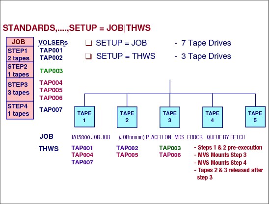
MDS setup options - JOB versus THWS
This sample setup job has 7 tapes requests in 4 job steps. Using SETUP=JOB on the STANDARDS statement would cause JES3 to assign 7 tape drives prior to execution for the job. Since there are only 5 tape units, the MDS places the job into the error queue.
Using SETUP=THWS, the same job would only need 3 tape units to execute the job. This is because the maximum number of units in any of the steps is 3. What is also true, is that the unit types must all be the same in this example.
In the sample the tape mounts are as follows:
•Prior to execution under the initiator, JES3 MDS would select 3 taoe units and issue mount messages to the operator to mount the first 3 tapes needed by the job. So, volsers TAP001, TAP002, and TAP003 are mounted.
•When step 1 completes, the first two tape units are now free but still belong to the job. The operator receives message to remove the tape volumes.
•When step 2 completes, the third tape unit is now free and TAP003 is removed by the operator.
•When step 3 starts, MVS allocation issues mount messages to the operator to mount volsers TAP004, TAP005, and TAP006. JES3 releases two tape units for other jobs to use.
•When step 4 starts, MVS allocation issues a mount message to the last tape unit owned by the job for volser TAP007. When step 4 completes, the last tape unit is free for other jobs to use.
When the job ends, the release of the still allocated tape units is done by MDS breakdown.
8.29 MDS allocation mode

MDS allocation mode
If manual allocation was specified during JES3 initialization or with the *F S,AL=M command, use the *S S command to allow a job to proceed to allocation processing. The *S S command is not required when automatic allocation was specified during JES3 initialization or by the *F S,AL=A command.
If ALLOCATE=AUTO (parameter default) is specified on the SETPARAM initialization statement or if you enter the *F S,AL=A command (automatic allocation), the job will proceed to the allocate queue. If you specify automatic allocation and SMS resources are required, the job will proceed to the system select queue. If ALLOCATE=MANUAL is specified on the SETPARAM initialization statement or if you enter the *F S,AL=M command, the job is put into the WAITVOL queue, from which it is released by entering the *S S command when the volumes are available (at which time the volume-request messages are issued).
Use the *F S VU=|VA= commands to:
•Make a volume unavailable for JES3 setup processing
•Make a volume available for JES3 setup processing
Tape volumes R67891 and R67892 are to be made unavailable:
*F,S,VU=(T-R67891,T-R67892)
Tape volumes R67891 and R67892 are to be made available:
*F,S,VA=(T-R67891,T-R67892)
8.30 Tape fetch processing

Tape fetch controls
The MDS fetch routine runs under the SETUP FCT and is the first phase of setup processing. Volume fetch messages are selected optionally by specifying FETCH=YES on the JES3 SETPARAM initialization statement. When you select the fetch option, JES3 issues volume fetch messages to indicate which volumes are required for specific jobs to execute. JES3 sends fetch messages to the console specified by the TAFETCH (for tape volumes) and DAFETCH (for direct-access volumes) parameters on the SETPARAM initialization statement. Volumes already mounted require no fetch processing, and volumes that have been fetched but not mounted get action-coded messages.
The message indicates the action required, volume type, volume serial number, tape label type, and data set name for the volume referenced by the specified job.
GET The volume that will be required by this job, but is currently not in use.
UNAV The volume has been made unavailable by the operator.
USES The volume that was previously fetched and has not yet been returned to the library.
If a volume is not found, it can be placed in an unavailable status. Use the *F S command to:
•Make a volume unavailable for JES3 setup processing
•Make a volume available for JES3 setup processing
The commands in the visual specify either tape (T) or disk (D) volumes that are to be made unavailable. The designated volumes remain unavailable until a *F S,VA= command is issued.
8.31 Volume mounting

Volume mounting
For main device scheduler requests, MDS verifies the mounting of the initial volumes a job requires on each device before the job can be selected for execution (unless deferred volume mounting is specified in the JCL).
MDS VERIFY processing
If verify encounters any correctable mount errors (and the operator remount count for the job is not yet reached) MDS re-issues mount messages for the correct volumes required for job execution.
Operator REMOUNT processing
The SETPARAM REMOUNT parameter specifies the number of times that an operator can retry to correct volume mount errors for a job before the devices for the job are released and allocation is restarted. The value of nnn specifies the number of retries allowed, from 0 to 255. For example, if REMOUNT=1 is specified, the operator can make two attempts to mount the volume--the original mount request and one retry request.
8.32 MDS mount messages and commands

MDS mount messages
Message IAT5200 indicates a job has allocated devices on the specified main.
Message IAT5210 indicates that a volume is required and/or that a device has been allocated. The ddname rather than the job name may appear in the JESMSGLG.
Operator commands fir outstanding mounts
After MDS has issued mount messages for jobs and those mounts have not occurred, these jobs can be displayed by issuing one of the following commands to determine which jobs are waiting for mounts:
D R,L - All messages
D R,L,Key=mount
D R,KEY - Messages with KEY names
D R,I,KEY=MOUNT,JOB=jobname - A single job
Mount failures
If MDS has detected an error on a device during the mounting of a volume previously requested in message IAT5210, message IAT5310 is issued.
By issuing the *F S,J=jobno,V command, MDS tries again to verify what the operator mounted. If this fails, the tape unit should be varied offline on all systems that share the device.
8.33 Device mount status

Device mount status
During JES3 starts, volumes that are mounted on the DASD devices are verified for their current status. This JES3 verify status is shown in the visual and the mount status indicates the results of the last attempt to perform volume verification.
*I,D command response displays the verify status in the IAT8572 message and indicates the results of the last volume verification. It may be one of the following:
VERIFIED The volume has completed MDS verification.
MOUNTED The volume is mounted on the indicated device.
NOT RDY The device is not ready.
NO RESP No response has been received from MDS verify on the local.
I/O ERR A permanent I/O error has occurred on the indicated device.
VOLID ERR An error was encountered reading the volume label.
ALLOCATED The device is allocated.
DUP VOL The indicated volume serial number is in use on another device.
OFFLINE The device is offline but contains a permanently resident volume.
INIT COMP The initial MDS verifies are complete ((that is), restart is complete).
NOT OPR The device is not operational.
EXPD ERR The expiration date has not yet been reached.
LOAD CHK Aload check error has occurred.
TIMEOUT An execute channel program has timed-out.
NO DEVICE There is no unit control block (UCB) for the indicated device.
GRP The device is dedicated to a job class group.
NET The device is dedicated to a DJC job network.
name The name of the job class group or DJC network ID to which the device is
currently dedicated.
8.34 Inquiry command for devices

Inquiry device command
The *I D,D= command allows inquiry messages to be displayed for all devices defined in the in the initialization statements using the DEVICE statement.
The first command on the visual uses a know device address. The second command uses a volume serial number as possibly the device address is not know by the operator.
The SHORT or S option of *I D D= display gives the status of a device on a specified main.
The fourth and fifth commands are used to display the role (global or local) of a main.
Device status
The device status in the visual (AV) indicates the device is available. Other possible device status conditions are as follows:
•AC - the device is in use by a setup job. (XUNIT status)
•ACO - the device is in use but has been varied offline to JES3. (XUNIT status)
•AC - the device is in use but is pending offline
•RS - the device is reserved by a setup job above a setup barrier. (XUNIT status)
•RSO - the device is reserved but has been varied offline to JES3. (XUNIT status)
•AV - the device is online and not in use. (XUNIT status)
•AVU - the device is online and not in use, but it is in the process of being unloaded.
•OFF - the device is offline to JES3. (XUNIT status)
•OFN - the device is offline because there are no paths available
•ACN - the device is allocated and is offline because there are no paths available
8.35 MDS volume and data set control

Volume use and mount attributes
Volume fetch, the first phase of MDS, is performed for all jobs entering MDS. This phase determines the volumes required by the job and, if necessary, instructs the operator to get the volumes from the library. This phase also eliminates those mains on which the job cannot run.
During fetch processing, JES3 builds volume entries and issues messages for volumes that have no entries in the SETVOL table which contains the volume serial number for each reference to a device managed by MDS.
As the fetch routine scans the JST entries, it builds a SETVOL table entry for each of the volumes required by the job. For SMS-managed data sets, JES3 is not concerned with and does not know about the volumes where the data sets reside. However, the fetch routine still creates a dummy SETVOL table entry since MDS is responsible for complex wide data set awareness. The fetch routine creates the SETVOL entry using a dummy volser. This allows the SMS-managed data sets to be distributed over a number of SETVOL entries. If a volume is not mounted, the fetch routine issues a fetch message to the operator.
Volume fetch messages are selected optionally by specifying FETCH=YES on the JES3 SETPARAM initialization statement. When you select the fetch option, JES3 issues volume fetch messages to indicate which volumes are required for specific jobs to execute. JES3 sends fetch messages to the console specified by the TAFETCH (for tape volumes) and DAFETCH (for direct-access volumes) parameters on the SETPARAM initialization statement. Volumes already mounted require no fetch processing, and volumes that have been fetched but not mounted get action-coded messages.
Device types other than tape or disk do not require operator action. If you do not specify the volume fetch option, jobs go directly into the system select stage of MDS if the job requires SMS-managed resources, or into allocation if the job does not require SMS-managed resources.
MDS allocation
The allocation phase of MDS uses allocation algorithms to provide required devices. When allocation is successful, JES3 issues mount request messages for all required volumes except:
•Deferred mount requests - where no mount is as yet requested but the device that the volume is to be mounted on is allocated to the user.
•Permanently resident volumes - where the mount is unnecessary
•Multi-volume mount - where only the first volume of a multi-volume data set is mounted; secondary volumes are not mounted until required.
During the volume verification JES3 issues messages that instruct you to mount a job's required volumes.
SETDSN and SETVOL tables
The SETDSN and SETVOL tables contain the data set names and volume serial numbers, respectively, for each reference to a device managed by MDS. The data set name entry table maps the SETDSN entry used by MDS to control the serialization and sharability of a particular data set.
Identifying resident data sets
During JES3 initialization you can identify data sets that are resident on all systems. Thereafter, when the names of these data sets appear as catalog references on a DD statement for a job, JES3 will bypass catalog searches (also called LOCATE processing) during the postscan phase of C/I service. Thus, you improve JES3 performance. To specify the names of the resident data sets, use the RESDSN initialization statement.
JES3 does not perform data set awareness processing for resident data sets. Therefore, do not specify SMS-managed data sets as resident data sets unless the data set can be accessed from only one processor or unless the user provides data set awareness. MVS provides data set integrity when a resident data set can be accessed from only one processor.
8.36 Managing JES3 device online/offline status
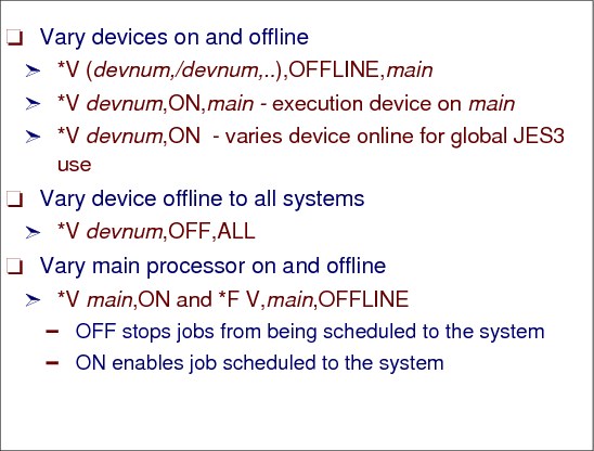
Managing JES3 device online/offline status
The online/offline status of a device controls whether the device is eligible to be allocated or not.
The *V command to makes JES3, and JES3-managed devices available or unavailable for JES3 scheduling. These devices include RJP lines, devices at BSC RJP or SNA RJP workstations, logical senders used by JES3 networking, and mains.
Vary tape devices 180 and 181 offline on SY1:
*V,(180,181),OFFLINE,SY1
Vary local main processor SY1 offline:
*V,SY1,OFF
Use the *V command to vary SMS-managed devices online or offline to any processor in the JES3 complex.
When varying a JES3-managed execution device online or offline to JES3 on a main, JES3 attempts also to vary the device online or offline to MVS. JES3 varies a device offline only if the device is not allocated. If you want the MVS status to differ from the JES3 status, you then must enter the MVS VARY command to change the MVS online/offline status of the device (after JES3 initialization or a JES3 *V). You should not, however, vary an online JES3-managed device offline to MVS.
Device in use
If you enter a *V xxx,OFFLINE command for a device that is currently in use (except for a tape drive that is in use on another system), JES3 will mark the device pending offline to JES3 and will not vary the device offline to MVS until it is unallocated.
|
Note: When varying a 3480 or 3490 tape device online or offline to JES3 as a JES3-managed device or a JES3 device, JES3 varies the device online or offline to MVS. JES3 also performs an ASSIGN (online) or UNASSIGN (offline). The device remains online and assigned to MVS only if it is online as a JES3 device or as a JES3-managed device. A device path must be online before the operator or JES3 can vary the corresponding device online to JES3 or MVS.
|
8.37 Data awareness in a JES3 complex
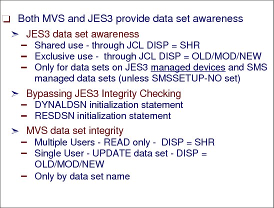
Data set awareness
In a JES3 complex both MVS and JES3 provide data set awareness. Data set awareness specified in the JCL DISP parameter ensures that:
•While one job is reading a data set another job does not change that data set.
•While one job is updating a data set no another job can read that data set.
•Two ways to establish the extent of VSAM data set sharing are the data set disposition specified in the JCL and the share options specified (SHAREOPTIONS) in the access method services DEFINE or ALTER command.
•Only one job at a time uses a sequentially accessed (serially reuseable) device that is attached to one or more processors
JES3 data set awareness processing
JES3 provides complex-wide data set awareness for managed data sets. MDS data set awareness is responsible for controlling access to data sets within a JES3 complex. This prevents jobs running in different processors in the complex simultaneously from updating a serially reusable resource (existing data set with DISP=OLD/MOD/NEW). To provide data set awareness for non-SMS managed data, MDS has to know the volumes associated with the data set. Non-DFSMS managed, new non-specific DASD data sets, do not have an associated volser and thus MDS cannot provide data awareness for them.
MVS allocation
MVS and MDS allocation consider a job's resource requirements at different levels. MVS allocation considers job requirements one step at a time for the processor executing the job; MDS considers the resource requirements for all the steps in a job for all processors in the loosely-coupled complex. These two approaches lead to the following differences between MDS and MVS allocation:
•MVS allocation: In systems that do not use JES3, jobs are presented to MVS based on criteria such as job class, priority, or WLM work classification. In these systems, a job's resource requirements are not known until the job entry subsystem selects the job for execution, and a system initiator begins the step allocation process. At each job step, MVS allocation attempts to satisfy the requirements for the step, in contention with every other job step currently executing on the same processor or in the sysplex. If the requirements cannot be met, MVS allocation gives the operator the option of canceling the job or allowing it to wait for resources. Thus, in a system that does not use MDS, there may be jobs executing and other jobs waiting for resources. The jobs waiting in MVS allocation hold critical resources (a system initiator, an address space, data sets, and possibly devices).
•Main Device Scheduler (MDS) allocation: With MDS, the resources (data sets, devices, and volumes) that a job requires are already set up when the job is passed to MVS for execution. Setup occurs while a job is in the JES3 address space, and the only system resource used while the job is waiting is the JES3 queueing space. MDS helps the system make maximum use of devices and allows jobs to run in a minimum amount of time once they are passed to the system for execution. Also, MDS cooperates with the workload management (WLM) component of MVS to ensure that the scheduling environments for jobs are honored.
MVS data set integrity
Before allocating data sets to a job, MVS enforces data set integrity for MVS-managed data sets. To ensure data set integrity, MVS does not allocate a data set to a job if:
•The job requests non-shared access to an allocated data set (JCL DISP OLD/MOD/NEW)
•The job requests shared access to a data set that is allocated as non-shared
MVS does not begin the allocation process until the integrity of all the data sets in the job has been enforced. When integrity has been established, MVS then begins allocating the resources needed for the job, one step at a time. MVS provides integrity for data sets within a single MVS system or across multiple MVS systems in a sysplex.
JES3 data set awareness
JES3 enforces data set awareness for:
•Data sets that are requested through DD statements that require JES3-managed devices
•Data sets that are requested dynamically that require JES3-managed devices
•Data sets that are SMS-managed, unless SMSSETUP-NO is specified on the SETPARAM statement.
•JES3-managed sequentially accessed devices that are attached to one or more processors
If a job requests a data set through a DD statement, JES3 enforces data set awareness before scheduling the job for execution. For dynamically requested data sets, JES3 enforces data set awareness at the time of the request.
To ensure data set integrity, JES3 denies a job's request for a data set if:
•The request is for non-shared access to an allocated data set
•The request is for shared access to a data set that is allocated non-shared
What happens to a job that is denied an allocation request by JES3? This depends on how the job requested the data set.
•If it was requested using a DD statement, JES3 does not schedule the job for execution at that time. The job must wait until all of the resources it needs are available.
•If the data set was dynamically requested, MVS will not allocate the data set to the job at that time. The job, however, can continue to execute.
Bypassing JES3 awareness checking
To bypass JES3 data set awareness checking for dynamically allocated data sets or permanently-resident volumes mounted on JES3-managed devices, code the data set names on a JES3 DYNALDSN initialization statement. If you bypass JES3 setup for permanently resident data sets, you also bypass JES3 data set awareness checking for those data sets. This happens for data sets specified on a RESDSN initialization statement. Although you bypass JES3 data set awareness checking, MVS data set integrity checking remains in effect.
8.38 IBM 3495 automated tape library data server

Automated tape library data server - ATLDS
The automated tape library dataserver (ATLDS) and its supporting software streamlines and automates the roles of the storage administrator, tape operator, and the tape librarian, and uses the concepts of SMS to manage the tape volumes within the library.
An automated tape library dataserver (ATLDS) consists of tape drives, tape cartridges, a tape cartridge storage area, input and output stations for inserting and removing cartridges, and a mechanism for moving tape cartridges among these areas. The volumes within an automated tape library are known as library-resident tape volumes. Tape volumes can also be located on shelves outside the automated tape library. These volumes are known as shelf-resident tape volumes.
Tape cartridges are stored and retrieved by an automated cartridge accessor. The cartridges are placed in an input station by the tape library operator. The cartridge accessor then scans the external volume label on the cartridge, carries the cartridge to the appropriate storage location, and places it into the library. When a volume mount is requested, the cartridge accessor retrieves the cartridge from the storage location, carries it to the requested drive, and mounts the cartridge in the drive. Upon completion of the tape operation, the tape cartridge is unloaded, the accessor retrieves it from the drive, and returns it to a storage location in the library.
However, the tape library operator can continue library operation during periods when the cartridge accessor is not operational. During this time the operator responds to commands displayed on the manual mode console. This is known as manual mode operation.
JES3 IBM tape library data servers
JES3 support for the 3494/3495 tape library data servers provided with DFSMS enables a JES3 installation to manage tape drives within an IBM 3494/3495 tape library data server. (The following text references the IBM 3495 tape library data server.
JES3 supports the definition and usage of one or more IBM 3494/3495 tape library data servers within a JES3 complex. The tape drives within a given library are subsetted into library device groups (LDGs) based upon the device type. JES3 uses specific esoteric names to direct tape allocations to devices within the correct library when the tape resides in a library, and to drives outside of a library when the tape is not resident within a library.
The esoteric names for devices comprising a LDG are conveyed to JES3 through the SETNAME initialization statement. These esoteric names, in conjunction with the SETNAME statement, allow JES3 to associate the devices to a device group, the device groups to a library, and the libraries to a JES3 complex.
3495 tape data sets allocation
DFSMS directs new data sets to the IBM 3495 Tape Library Dataserver using the data class, storage class, and storage group information specified in JCL or provided by Automatic Class Selection (ACS). Storage class identifies the data set as DFSMS managed mountable. Data class is used to determine the required cartridge and device type. Storage group is used to determine the eligible 3495 libraries. Requests for old data sets are directed to a 3495 only when the volume or volumes containing the data set are located within a 3495. Eligible device types are determined from the cartridge type and recording format.
JES3 initialization statements for the 3495
JES3 initialization deck must include SETNAME, DEVICE and HWSNAME statements for the 3495. These statements define the 3495 to JES3, ensuring that non-library requests are not allocated to 3495 tape drives.
Neither JES3 nor DFSMS verifies that a complete and accurate set of initialization statements are defined to the system. A 3495 definition that is either incomplete or inaccurate may result in jobs failing allocation or other unpredictable results.
Before defining the devices within a library to JES3, they must be properly defined to MVS using the hardware configuration definition (HCD) program. Unlike a JES2 environment, a JES3 operating environment requires the specification of esoteric unit names for the devices within a library. These unit names will be used in the required JES3 initialization statements.
Each device within a library must have exactly four (4) special esoteric names associated with it. These are:
1. The complex-wide name, this is always: "LDGW3495."
2. The library-specific name, this is an 8-character string composed of "LDG" prefixing the 5-digit library identification number.
3. The complex-wide device type.
4. A library-specific device type name, which consists of the 5-digit library device number prefixed by a 3-character device type identifier.
These esoteric names should be defined and the input for the JES3 initialization stream checker obtained before making changes to the JES3 initialization stream.
Device-specific library unitnames
A library-specific device type name, which consists of the 5-digit library device number prefixed by a 3-character device type identifier.The following example specifies the name to be used for each device type.
Device Type Complex-wide Library-Specific
unitname Device Type Device Type
unitname unitname
__________________________________________________________
3490 LDG3490 LDDnnnnn
3490E LDG3490E LDEnnnnn
3590-1 LDG3591 LDBnnnnn
3590E1x LDG359E LDCnnnnn (Note 1)
3590H1x LDG359H LDFnnnnn (Note 1)
3592 LDG359J LDJnnnnn (Note 2)
Notes:
1. IBM TotalStorage Tape System 3590 Models E1x/H1x
2. z/OS DFSMS Software Support for IBM System Storage TS1120 Tape Drive (3592)
There is a different nomenclature for encrypted versus unencrypted for the 3592. LDLnnnnn indicates encrypted, LDKnnnnn indicated unencrypted (see APAR II14350).
8.39 MVS UNITNAMEs

MVS UNITNAMEs
MVS UNITNAMEs must be defined for all 3495 library device groups. The visual shows the UNITNAMEs defined for the library device groups in the configuration example. Note the following:
•The complex-wide name, LDGW3495, includes all devices in all libraries.
•The library-specific names, LDG123DE and LDG345DF, include devices from their respective libraries.
•The complex-wide device type names, LDG3490 or LDG3490E, include all devices of the same type, in all libraries.
•The library-specific device type names, LDD345DF, LDE123DF, and LDE123DE include all devices of the same type within their respective libraries.
In order for JES3 to manage SMS managed mountable requests for the ATLDS devices, the ATLDS specific unit names has to be added to the JES3 initialization stream (SETNAME and HWSNAME statements).
The DFSMS module IFG0JES3 uses the LDxccccc unit names when it provides library device unit type conversion for JES3. JES3 uses IFGXATL macro to invokes IFG0JES3 module services.
8.40 Coding ATLDS SETNAME statements

Coding ATLDS SETNAME statements
Include a SETNAME statement for each XTYPE group of ATL tape devices. The NAMES list for the SETNAME statement must include all required library device groups. It must not include any generic or esoteric names (such as 3490, 3480X, SYS3480R). The omission of these esoteric and generic names is required to prevent tapes from being mounted on unsuitable devices. The names specified must be defined to MVS as esoteric names.
The grouping of library devices into XTYPE groups is the same process for all other JES3 managed devices. The XTYPE groups are determined by the special esoteric names assigned during the HCD processing and associating the esoteric name to a device group.
The following guidelines will ensure correct generation of the SETNAME statements:
•There are always four esoteric names in the NAMES= list. These names are the special esoteric names that are used to identify library resident devices.
•There can never be esoteric names pertaining to different device types in the same list.
•There can never be two esoteric names for 3490, 3490E or 3590 device identifiers in the same list.
•There must be a LDEnnnnn value and vice versa if an LDG3490E exists. This is true for LDG3490 and LDDnnnnn, and LDG3591 and LDBnnnnn also.
8.41 ATLDS DEVICE and SETNAME statements

SETNAMES with tape
The visual illustrates the two 3495 libraries defined for this configuration, as follows:
•Library 1 (sequence number 123DE) has only 3490E tape drives.
•Library 2 (sequence number 345DF) has both 3490 and 3490E drives.
The grouping of library devices into XTYPE groups is the same process for all other JES3 managed devices. The XTYPE groups are determined by the special esoteric names assigned during the HCD processing and associating the esoteric name to a device group.
SETNAME statements for the two libraries are shown in the visual. Note the following specifications:
•Three XTYPEs are required because of different unit names used for 3490E devices in the two libraries.
•Ordinary esoteric or generic unit names such as 3480, 3480X, 3490, SYS3480R and SYS348XR, are not specified.
•Installation specific esoteric names such as TAPE or CART are also not used to describe the library devices.
|
Note: Your library ID number is printed just below the logo plate of the 3495, on the side containing the convenience I/O station.
|
DEVICE statement example
Include a DEVICE statement for each tape library drive in the complex. The XTYPE name must be unique for each device type within a library and cannot span libraries. You should not specify the 3495 as a JUNIT, or use the DTYPE or JNAME parameters. The absence of the DTYPE, JNAME and JUNIT parameters will prevent inadvertent and unsuccessful use of a library device by a JES3 dynamic support program (DSP).
JES3 functions with limitations
The following functions have limited capability for the 3495 in the JES3 environment:
•Support units
•Device connectivity
•Storage group states
•Scratch integrated cartridge loader requests
•Mixed JES3-managed and non-managed devices
•Library device groups specified in JCL
JES3 support unit limitations
3495 tape drives cannot be used as support units by JES3 dynamic support programs. Therefore, you should not specify DTYPE, JUNIT, and JNAME parameters in your initialization deck. JES3 does not prevent 3495 drives from being defined as support units. It also does not prevent them from being allocated to a dynamic support program. If this does occur, however, the dynamic support program must be canceled and restarted with a non-3495 tape drive.
8.42 ATLDS HWSNAME statements
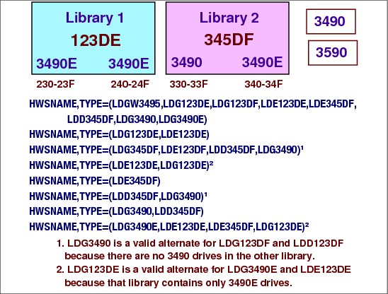
HWSNAME with tape
Build the HWSNAME statements for your library device groups using the following rules:
•The complex-wide library name includes all other LDGs as alternates.
•The library-specific name includes all LDGs for the corresponding library as alternates. The complex-wide device type name is also included as an alternate when all tape devices of a specific type are housed within a single 3495.
•The complex-wide device type name includes all library-specific device type names. When all devices of a specific type are contained within a single 3495, the complex-wide device type name is the same as the library-specific name. In this case, the library-specific name should also be specified as an alternate.
•The library-specific device type name includes the following alternate names:
– When all drives within the 3495 are of the same device type, the library-specific device type name is the same as the library name. The library-specific name should be specified as an alternate.
– When these are the only drives of this type in the complex, the complex-wide device type name is the same as the library-specific device type name. Therefore, the complex-wide device type name is specified as an alternate.
HWSNAME statement guidelines
The following guidelines will ensure correct generation of the HWSNAME statements.
•There is a one to one correlation to HWSNAME statements as to special esoteric names defined in HCD.
•There can never be esoteric names in the TYPE= lists that are not one of the special esoteric names. Similarly, your existing HWSNAME statements for tape devices must not have any of these special esoteric names in their TYPE= lists.
Following is an example of a HWSNAME statement:
HWSNAME,TYPE=(LDGW3495,LDG123DE,LDG3490E,LDE123DE)
8.43 Virtual tape server (VTS) tape libraries

Virtual tape servers
A way for optimizing tape media is through the virtual tape server (VTS) tape library hardware. VTS can be used with or without tape mount management. It does not require ACS routine or other software changes.
You can reduce the number of tape cartridges, devices, and automated tape libraries by implementing an IBM TotalStorage® Virtual Tape Server (VTS) or an IBM TotalStorage Peer-to-Peer Virtual Tape Server (PtP VTS). This virtual tape subsystem consists of virtual tape devices, virtual tape volumes, tape volume cache (DASD), and hierarchical storage management software.
The PtP VTS addresses data availability, system availability, remote copy, and data vaulting needs by coupling together two stand-alone VTSs.
From a host perspective, the virtual system looks like multiple 3490E control units, each with 16 tape devices. Each emulated device is called a virtual tape device. The virtual system handles all 3490 tape commands. Each virtual device has the following attributes:
•Has a host device address
•Is included in the I/O generation for the system
•Is varied online or offline to a host
•Signals ready when a virtual volume is loaded
•Responds to and processes all 3490E tape commands
•Becomes not ready when a virtual volume is rewound and unloaded
•Indicates that it has a cartridge loader
•Can be associated with a pool of scratch volumes that allow very fast mount access for scratch mounts
Note: The active status of the cartridge loader depends on the availability of scratch volumes in the assigned pool.
VTS Tape Libraries
The IBM TotalStorage Peer-to-Peer Virtual Tape Server (PtP VTS) the IBM 3494 can be used to join two separate Virtual Tape Servers into a single interconnected system. Supported libraries are the IBM TotalStorage 3494 Tape Library and the IBM System Storage® TS3500 Tape Library. The two virtual tape systems can be located at the same site or at different sites that are geographically remote. This provides a remote copy capability for remote vaulting applications.
The Peer-to-Peer VTS appears to the z/OS host as a single automated tape library with 64, 128, or 256 virtual tape drives and up to 500,000 virtual volumes. The configuration of this system has up to 3.5 TB of Tape Volume Cache native (10.4 TB with 3:1 compression), up to 24 IBM TotalStorage 3592 tape drives, and up to 12 IBM TotalStorage 3590 tape drives models B1A, E1A, or H1A, and up to 16 host ESCON or FICON® channels.
A Peer-to-Peer VTS configuration is built from the following components:
•The 3494 Virtual Tape Controller (VTC)
•The 3494 Auxiliary Tape Frame Model CX1
•The 3494 Model B10 and B20 Virtual Tape Server attached to a IBM tape library
•Peer-to-Peer Copy features
VTS Tape Allocation in JES3 Environments
Setup recommendations:
•UNITNAME
– Never specify a virtual tape drive as an alternate for another tape library specific unit name.
– Separate the tape allocations to the VTS from other real tape drives in the same 3494 Tape Library.
•DFSMS
– To define the VTS as a JES3-managed drive, use the following definitions in the JES3 initialization stream.
• Define JES3 managed drives in the VTS through DEVICE statements.
• Define JES3 drive names through SETNAME statements.
• Define which device names are subsets of other device names through HWSNAME statements.
•Do not use the same generics/esoterics inside and outside tape library for JES3-managed tapes.
In a JES3 environment, where MVS allocation is not used, JES3 attempts to spread scratch mount requests across all library devices. For specific mounts, subsystem affinity cannot be used. In a JES3 environment, where JES3-managed devices get assigned at pre-execution time before MVS allocation is invoked, a different approach can be used. JES3 can be set up, through the definition of ADDRSORT=NO in its INISH deck, to use the devices in the defined order, evenly distributing workload across the VTSs.
8.44 DEVICE statements for VTS

DEVICE statements for VTS
From a host perspective, the virtual system looks like multiple 3490E control units, each with 16 tape devices. Each emulated device is called a virtual tape device. The virtual system handles all 3490 tape commands.
All host interactions with data in a VTS are through virtual volumes and associated virtual tape devices; there is no direct access to the data on a physical cartridge or device. Host application data is written and read as if it is stored on a real Standard or Enhanced Cartridge System Tape; however, within the system it is really stored on DASD. All tape read and write commands are translated to read and write data records to or from DASD. Volumes residing on the DASD are called virtual volumes.
One of the key features of the VTS is its capability to automatically use the 3590 and 3592 tape technology cartridge storage capacity. With a VTS, volumes being created by the host applications are stored in a tape volume cache which is built from DASD devices. The size of the tape volume cache is greater than the capacity of a native cartridge. The tape volume cache can potentially contain hundreds of tape volume images called virtual volumes, depending on the size of the volumes and tape volume cache.
Through tape volume cache management policies, the VTS moves virtual volumes from the tape volume cache to a native cartridge managed by the VTS system. As virtual volumes are moved from the tape volume cache, they are stacked end to end on the cartridge and take up only the number of bytes written by the host, effectively using all of the storage capacity of the cartridge.
8.45 SETNAME statements for VTS

SETNAMEs with VTS
The SETNAME statement is used for proper allocation in a JES3 environment. For tape devices, it tells JES3 which tape device belongs to which library. This is done by specifying the relationships between the XTYPE values (coded in the DEVICE Statement) and the LDG names shown in the visual. A SETNAME statement must be defined for each unique XTYPE in the device statements.
Device addresses 510-513 are 3590 drives.
Device addresses 520-521 are 3490E drives.
Device address 5A0-5BF are virtual 3490E drives.
The rules for this SETNAME statement are:
•Each SETNAME statement has one entry from each LDG category.
•The complex-wide library name must be included in all statements (LDGW3495).
•A library-specific name must be included for XTYPEs in the referenced library.
•The complex device type name must be included for all XTYPEs of the corresponding device type in the complex.
•A library-specific device type name must be included for the XTYPE associated with the devices in the library.
8.46 HWSNAME statements for VTS
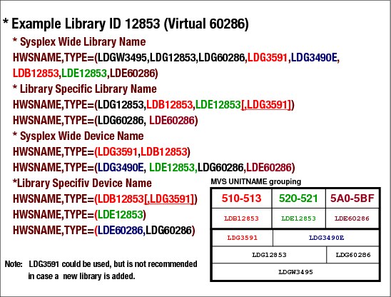
HWSNAME statements for VTS
HWSNAME,TYPE=(devname[altname,...])
HWSNAME statement guidelines for libraries:
•Alternate names must be a subset of or equal to the primary device name.
•List all names as the primary device name once, even if no alternates are possible.
•Do not list names as alternate which span multiple libraries
•unless the primary does.
•The complex-wide library name LDGW3494 must include all other LDGxxxxx names as alternates.
•The library-specific name LDGxxxxx must include all LDG names for the corresponding library alternates.
•The complex-wide device type name LDG3490/LDG3490E must include all library-specific device type names.
8.47 Operator control of jobs in MDS

Operator control of jobs
Operators can determine which jobs are waiting for resources by issuing the *I S command. *I S A command lists jobs waiting in allocate queue. *I S,A,J=jobno for a specific job.
The *I S command to displays the status of jobs currently in setup or the status of volumes and data sets controlled by MDS. If none of the optional parameters is specified, the status of all mains in the complex and a summary of the MDS queues are displayed.
*I S command operands:
•,ALWIO - allowed (ALWIO) and maximum (MAXIO) number of asynchronous I/O requests
•,A[,SUMM][,J=jobno] - jobs in the MDS allocate queue
•,E[,J=jobnos] - jobs in the MDS error queue
•,R[,J=jobnos] - jobs in the MDS restart queue
•,SS[,J=jobno] - jobs on the MDS system select queue
•,SV[,J=jobno] - jobs on the MDS system verify queue
•,U[,J=jobnos] - displays unavailable volumes and jobs waiting for unavailable volumes
•,B - jobs currently having their resources deallocated
•,D=dsn - displays data set status and the status of associated volumes
•,DE=dsn - displays data set status, the status of associated volumes, and using jobs
•,F - jobs currently in the MDS fetch queue
•,THWSSEP - current HWS option for separation of scratch and specific requests
•,V - jobs waiting to be verified by setup
•,V=vol[,E] | ALL[,E] | RES - displays status of the volume and associated data sets
•,W - jobs currently in the MDS WAITVOL queue (waiting for the *S SETUP)
8.48 Operator control of jobs in MDS

Operator controlling jobs on allocate queue
When MDS allocation is not successful because needed devices, volumes, or data sets are unavailable, the job is queued for another attempt. If it remains on the allocate queue, MDS builds/refreshes an allocation requirements list (ARL) for the job. The ARL is a list of all resources unavailable to the job. The ARL table is scanned prior to giving the job another allocation attempt (unless the job is above the priority barrier) to determine if allocation should be attempted. You define the priority barrier (or SETUP barrier) with the SBAR parameter on the SELECT initialization statement. The *I S A command provides detailed information with a list the reasons why the job is in the indicated main device scheduler (MDS) queue, as follows:
*I S A J=46281
IAT5642 MDS ALLOCATION NOT YET ATTEMPTED FOR JOB VAINIATL (JOB46281) ON SC43 RESOURCE NAVAIL
IAT5648 MDS FAILED TO ALLOCATE THE FOLLOWING FOR JOB VAINIATL (JOB46281) ON SC43
IAT5645 1 OUT OF 1 REQUESTS FOR DEVICE=VOL001
Message IAT5645 indicates the resources that MDS could not allocate for the job and main indicated in message IAT5648.
Determine why the job is waiting
The *I D,D= command inquires on the device characteristics to determine why the volume on the specified device (LDK31233) is not available. The IAT8572 message indicates the that the resource (device) is offline. The operator response can be to vary the device online:
*V B22,ON,SC43
8.49 MVS dynamic I/O reconfiguration and JES3

MVS dynamic I/O reconfiguration and JES3
You can use the Hardware Configuration Definition (HCD) program to add, delete, or change JES3 defined devices. These can be JES3 global devices (JUNIT), execution devices (XUNIT), or shared devices (both JUNIT and XUNIT). When making these changes, be careful not to introduce subgeneric splits, define devices to JES3 but not to MVS, or define devices as one device type to JES3 but a different device type to MVS.
If you make a mistake, JES3 will tolerate the error and initialize (if there are no other errors with higher impact); however, you should correct the error and perform a hot start with refresh at your earliest convenience.
Adding devices
Adding a device to HCD that is also to be defined to JES3 requires a corresponding device definition in the JES3 initialization stream. The device can be defined by an individual DEVICE statement or it can be included in a range of devices by using the NUMDEV parameter on a DEVICE statement, which defines the first device in the range. The device must be specified on the XUNIT, JUNIT parameter, or both. The processor can be defined by name or it can be defined implicitly by using the system name *ALL. If you use *ALL, the HCD configuration for every processor must define the device the same way.
If you are adding a new device type or changing the esoteric groupings of devices, you may also need to add or change SETNAME statements. To define the new device to JES3, you must perform a hot start with refresh using your modified initialization stream after activating the configuration in HCD. All local processors will be automatically restarted when the hot start with refresh occurs, so you must activate the configuration on all processors before you perform the hot start with refresh.
|
Note: Even if you are adding the same device that was previously deleted without an intervening JES3 restart, a hot start with refresh must be performed after activating the configuration in HCD to allow the internal control blocks associated with the device to be built.
|
Changing devices
When you use HCD to change the characteristics of an existing JES3 defined device in HCD, you do not need to IPL the processor or restart JES3.
Deleting devices
Deleting a JES3 defined device from HCD does not require any immediate JES3 change; however, you should plan to delete the device from JES3 and perform a hot start with refresh with the modified initialization stream at your earliest convenience after activating the configuration.
HCD only needs to identify if a device is online or offline, and bases whether to allow the deletion from the MVS configuration solely on that criteria. If the device is online, it will not allow deletion of the device. If the device is offline, it will delete it.
FSS devices require special consideration if their configuration in MVS is being dynamically modified. An FSS might have more than one FSA device assigned to it. Some of the devices could be active and online, and some inactive and offline. HCD will allow dynamic deletion of the offline devices. However, a subsequent JES3 hot start with refresh will fail if any of the devices under the FSS are active, even if the DEVICE statements for the previously deleted through HCD devices have been removed from the JES3 Initialization stream. A hot start (without refresh) will fail whether the FSS is active or inactive.
|
Note: Do not use hot start to start JES3 after a dynamic deletion of FSS devices from the MVS configuration. Only use hot start with refresh to start JES3 after deactivating all FSA devices assigned to the FSS.
|
8.50 Move a DASD volume to a new address

Moving DASD volumes
With the *V command, use the RECOVER parameter to logically move a permanently resident volume to a new address. The RECOVER parameter forces vary online and volume verification processing for a single direct access set-up device. The device that you specify on this command is treated as if it has a device characteristic of removable. Other devices that have the same volume serial as the specified device are also treated as removable devices. Parameter restrictions are as follows:
•The issuing console must have level 15 authority
•You must specify a main name
•You cannot move non-DASD volumes
•You cannot move JES3 spool volumes
•You cannot move a DASD volume that has a mount pending
•You cannot move a DASD volume involved in an active DDR swap.
|
Attention: Use this parameter only with the approval of your system programmer. Improper use can damage your JES3 system.
|
Message IAT5918
JES3Vxy indicates a copy of the verify response message from an MVS processor described as follows:
x - verify descriptions
• 1 character, 0-F, or a blank (X'40'), corresponding to the following verify descriptions:
0 - xxxxxx VERIFIED - volume xxxxxx has completed MDS verification.
1 - xxxxxx,L MOUNTED - volume xxxxxx is mounted on the indicated device (L is label type).
2 - UNIT NOT READY - the device is not ready.
3 - NO RESPONSE - no response has been received from MDS verify on the main.
4 - VERIFY TIMEOUT - a timeout occurred during execution of a channel program.
5 - NON-EXISTENT DEV- there is no unit control block (UCB) for the indicated device.
6 - PERM I/O ERROR - a permanent I/O error has occurred on the indicated device.
7 - VOLID READ ERROR - an error was encountered reading the volume label.
8 - xxxxxx ALLOCATED - device xxxxxx is allocated with this volume.
9 - DUPLICATE VOLID - the indicated volume serial number is in use on another device.
A - xxxxxx OFFLINE - device xxxxxx is offline but contains a permanently resident
B - RESTART COMPLETE - end of initial verifies (during connect).
D - NO PATHS AVAIL - the device is offline to MVS.
E - EXPR DATE ERROR - the expiration date has not yet been reached.
F - TAPE LOAD CHECK - a load check error has occurred.
y - source of the verify request
•A - device arm response (errors only).
•B - initial verify response.
•C - SYSUNITS ACL update.
•M - volume mounted by operator.
•R - MDS message route.
•U - unload complete.
•V - vary online response.
z - UCB/STATUS byte
•P - MVS permanently resident
•M - MVS mounted
•blank - removable
JES3V1V indicates In the IAT5918 message in the visual:
1 - xxxxxx,L MOUNTED - volume xxxxxx is mounted on the indicated device (L is label type).
V - vary online response.
IAT8572 message
•JES=
– R the volume (if any) is removable by JES3.
– M the volume is JES3 mounted.
– P the volume is permanently resident to JES3.
•OS=
– R the volume (if any) is removable to the operating system.
– M the volume is reserved by the operating system.
– P the volume is permanently resident to the operating system.
– MS the volume is reserved by the operating system and is SMS-managed.
– PS the volume is permanently resident to the operating system and is SMS-managed.
..................Content has been hidden....................
You can't read the all page of ebook, please click here login for view all page.