

RJP and NJE
With remote job processing (RJP), you can submit work to JES3 from locations significantly distant from the JES3 global processor. The points of origin for RJP jobs are called workstations. A workstation can be a single I/O device, a number of separate devices, or one of the allowable processors with its devices.
Data travels between workstations and the JES3 global processor over communication lines or adapters that substitute for communication lines. JES3 processes the jobs it gets from workstations as if it had received the jobs locally. JES3 can write output of remotely-entered jobs on local devices or it can transmit the output to the originating workstation. JES3 can also transmit output to any other workstation connected to the global processor.
JES3 offers installations two kinds of protocols:
•Binary synchronous communication (BSC) multi-leaving protocols, where a separate communication line is needed for each device at a workstation.
•IBM systems network architecture (SNA) protocols, where many devices can share a communication line.
Remote job processing with BSC multi-leaving protocols is called BSC remote job processing (RJP), and that with SNA protocols is called SNA remote job processing (RJP).
BSC remote job processing
Features of BSC remote job processing include:
•Password protection for an RJP line, a device, or both.
•Message routing. JES3 sends job-started, job-ended, and abnormal-ending messages.
•Support for programmable and non-programmable devices.
•Output suspension for non-programmable devices.
•Compressed (removal of repeated characters) data support for inbound data.
•Connection through leased or dial-up communication lines.
•Remote console support.
•Work station operator inquiry by data set origin or destination.
•Error recovery and error statistics.
•Message queuing for signed-off consoles.
•System management facilities (SMF) recording.
•Interface with remote terminal processor (RMT) programs for managing devices connected to processors at workstations.
SNA remote job processing
Features of SNA remote job processing include:
•Password protection for accessing an RJP workstation.
•Message routing. JES3 sends job-started, job-ended, and abnormal-ending messages.
•SNA data transmission protocols.
•Connection through leased or dial-up communication lines.
•Multiple logical unit support for concurrent data transmission between JES3 and the console, readers, and printers at a workstation.
•Compression and compaction (substitution of characters according to rules).
•ASCII support. JES3 can handle ASCII or EBCDIC character sets.
•Block size selection.
•Remote console support.
•Work station operator inquiry by data set origin or destination.
•Error recovery and error statistics.
•Message queuing for signed-off consoles.
•System management facilities (SMF) recording.
JES3 network job entry (NJE)
The JES3 network job entry (NJE) facility is similar to remote job entry (RJP) in that they both provide extensions to a computer system. In its simplest terms, NJE is "networking" between systems that interact as peers, whereas RJP is networking between JES3 and workstations. The main difference between them is one of overall compute power and processor location. Remember, RJP is an extension of a single JES3 complex that allows jobs to be submitted from, and output routed back to, sites that are remote to the location of that system. NJE provides a capability to link many processor complexes into a processing network. Each complex can be located on the same physical processor, side-by-side in a single room, or across the world in a network of thousands of nodes. The important difference is that a processor and its local and remote devices make up a node. Three or more attached nodes make up an NJE network.
JES3 network job entry (NJE) allows JES3 users at one JES3 complex to send jobs to another JES location for execution, to send output (SYSOUT) data to another JES location for processing, and to send jobs, commands, and messages to another JES location or to a non-JES location.
Therefore, JES3 can become a part of a network comprised of a Job Entry Subsystem 2 Network Job Entry (JES2 NJE) configuration, a Virtual Machine/Remote Spooling Communications Subsystem (VM/RSCS) configuration, a VSE/POWER system, as well as other JES3 complexes.
JES3 provides three types of networking protocols, binary synchronous communication (BSC) protocols, systems network architecture (SNA) protocols, and transmission control protocol/internet protocol (TCP/IP) protocols. Each type enables a complex to participate in a data communications network, and to pass jobs, commands, messages, and system output (SYSOUT) data between nodes in that network.
The JES3 SNA/NJE protocol in combination with z/OS BDT Version 2 provides a JES3 complex with systems network architecture/network job entry (SNA/NJE) capability.
A JES3 complex that uses the BSC/NJE, SNA/NJE, or TCP/IP/NJE protocol might also communicate with nodes that use one of the three protocols. This means that the NJE network might consist a mixture of the three protocols.
14.1 Defining BSC remote job processing

RJPLINE (BSC remote job processing line)
Use the RJPLINE initialization statement to define the characteristics of a single BSC line (and its respective adapter) that will be used by the JES3 global for remote job processing. You can also use this statement to assign a specific RJP work station, defined by the N parameter of an RJPTERM statement, to this line. Considerations:
•One RJPLINE statement is required for every adapter to be accessed by RJP.
•The T parameter (terminal to be assigned to this line) must match the N parameter on an RJPTERM statement and the JNAME parameter on a CONSOLE statement.
•Use the password parameter (P) to specify a e password used to protect the RJP line.
RJPTERM (BSC remote job processing terminal)
Use the RJPTERM initialization statement to define a single remote BSC work station to the JES3 system. This statement causes a default description to be provided for each work station device (printer, punch, or card reader) indicated by the PR, PU, or RD parameters along with the operating characteristics of the work station. If the JES3 default characteristics for a remote printer or punch device are not acceptable, a DEVICE statement should be coded to indicate desired characteristics. If a work station is to have the facilities of a JES3 operator console, then a CONSOLE statement must be coded.
Modifications with a command (*F T) or JES3 restart with cold, warm, or hot start with refresh for all parameters.
14.2 Defining SNA remote job processing

COMMDEFN (communication SSI definition)
Use the COMMDEFN statement to specify the optional user communication subsystem interface (VTAM) parameters. Considerations:
•Ensure that the value you specify on the P (password) parameter is the same as the password specified on the PRTCT parameter of the VTAM APPL application definition.
RJPWS (SNA work station characteristics)
Use the RJPWS initialization statement to describe each SNA work station's characteristics to the JES3 system. This statement causes a default description to be provided for each work station device (printer, punch, or card reader) indicated by the PR, PU, or RD parameter along with the operating characteristics of the work station. Considerations:
•Use the CONSOLE statement to define console support at a remote work station. You can use the *F CONFIG command to add a console.
•Use the DEVICE statement to define remote printers and punches. You can use the *F CONFIG command to add additional devices to the remote work station.
•If the JES3 default characteristics for a remote printer or punch device are not acceptable, you should code a DEVICE statement to indicate desired characteristics.
Modifications with a command (*F T and *F CONFIG) or JES3 restart with cold, warm, or hot start with refresh for all parameters.
See z/OS JES3 Initialization and Tuning Reference, SA22-7550 for keyword parameter details.
14.3 Controlling RJP

Controlling JES3 RJP
Activating RJP:
•Use the *X RJP command to activate BSC RJP. When BSC RJP is operational, you will receive message IAT7500. BSC RJP immediately starts any lines for which automatic start was specified during initialization.
•Use the *X SNARJP command to activate SNA RJP. When SNA RJP is operational, you will receive message IAT2801.
If AUTO=(Y,luname) is coded on the RJPWS initialization statement for a workstation, the indicated logical units (LUs) at that workstation are automatically logged on when SNA RJP becomes active. Before the SNARJP DSP can be called, VTAM must be active and the required VTAM networks must be varied online.
Restarting RJP:
•Use the *R RJP command to end a BSC RJP session or activity on any line and then start it again. The command can be used to end activity immediately or as though the normal workstation sign-off occurred. This command has the same effect as entering an *C RJP command followed by an *S RJP command for the same line(s). After the line is restarted, communication with the workstation must be reestablished through the workstation start-up procedure.
•Use the *R SNARJP command to end a SNA RJP workstation and then start it again. This command has the same effect as entering an *C SNARJP command followed by an *S SNARJP command for the same workstation. It can be used to end activity immediately or conditionally. After the workstation is restarted, communication with the workstation must be reestablished by using the workstation start-up procedure.
Stopping RJP:
•Use the *C RJP command to stop a BSC RJP session or activity on any line. The command can be used to stop activity immediately or as though a normal workstation sign-off occurred.
•Use the *C command to halt the SNA RJP network, a SNA RJP workstation, or processing on a SNA RJP device.
Changing RJP:
•Use the *F T command to:
– Specify the action to be taken if a remote printer or punch becomes "not ready".
– Assign a password to a line or to specify that no password is required.
– Hold or release jobs that are being submitted from BSC RJP workstations.
– Hold or release jobs on the JES3 job queue that are being submitted from a SNA RJP.
– Specify whether a line will be started automatically when BSC RJP is reinitialized.
– Control the RJPSNPS facility.
– Disable or enable an automatic reader at a SNA RJP workstation.
– Disable or enable SNA RJP tracing.
– Change the number of times an incorrect password is allowed from a SNA RJP workstation before logons are inhibited.
– Change the group name on a SNA or BSC RJP workstation.
•You use the *F CONFIG command to make configuration dynamically changes to SNA RJP definitions. The command is equivalent to adding the following SNA RJP initialization statements to the initialization stream:
– RJPWS - SNA RJP Workstation Characteristics
– CONSOLE - SNA RJP Consoles
– DEVICE - SNA RJP Devices
Signing on or off at a BSC RJP workstation:
•Before data transmission to a BSC remote workstation can begin, the workstation operator must sign on to JES3. When BSC RJP is active and the line started, use the /*SIGNON card to sign on to JES3. Format:
Column Description
1-8 /*SIGNON
16-20 Workstation name: a five-character name for the remote
workstation requesting sign-on.
22 A (or blank): A, for programmable workstations only, specifies
automatic reader.
23 R (or blank): R, for nonprogrammable workstations only,
specifies the output suspension feature.
25-32 Line password: a one- to eight-character password which must
have been defined on the RJPLINE initialization statement.
35-42 Workstation password: a one- to eight-character password which
must have been defined to RACF if RACF password protection for
RJP is active.
44-51 New workstation password: You can use these columns to provide a
new password if RACF password protection for RJP is active and
you want to change the workstation password.
The workstation can end the use of the BSC RJP line by submitting a /*SIGNOFF card.
Systems network architecture (SNA) remote work stations must use the LOGON command instead of the /*SIGNON statement to notify JES of a connection request.
14.4 Remote job processing (RJP)
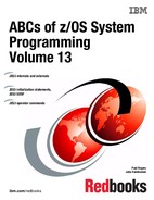
RJP FCTs
This figure shows the FCTs used for processing of RJP functions, both SNA and BSC.
CONSDM The CONSDM DSP processes JESMSG and RJP message spooling.
SNARJP Synchronous data link control (SDLC) protocols within the network architecture (SNA) is used. Remote devices using SDLC protocols are managed by the SNARJP DSP. With SNA RJP, line protocols are managed VTAM.
RJP BSC RJP (binary synchronous communication remote job processing) include two logical sections: the RJP line manager DSP, which controls all the line activities; and the remote terminal access method (RTAM), which blocks data into and deblocks data out of the appropriate transmittal buffers. The RJP line manager and the RTAM RJPPUT processing routines can execute simultaneously under different tasks; but the line manager must run under the primary task (IATNUC) because it interacts with other non-multi-tasked JES3 DSPs.
WTR Output can be sent to a variety of devices. For RJP attached devices that are not driven by the JES3 global address space, the WTR DSP passes output to the appropriate interface. This can be RJP, SNARJP, or NJE services.
CR Reader processing takes place in the JES3 global address space. The reader phase reads jobs from any of the sources mentioned above and place the jobs on JES3 spool in batches for later processing. Jobs submitted from BSC RJP remote stations are processed as if they come from a local card reader. Jobs from SNA RJP use a special logical record (LR) interface.
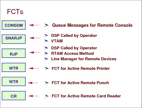
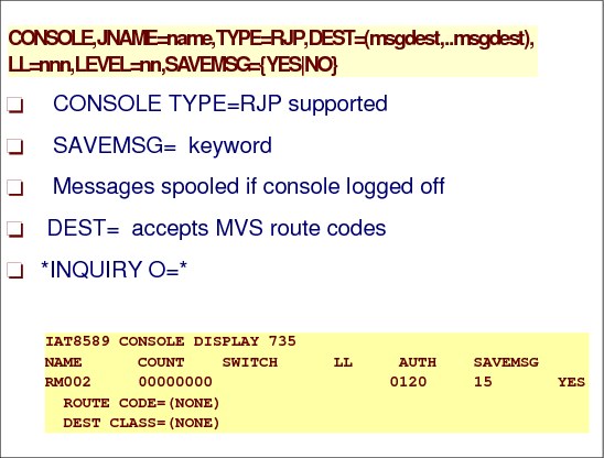
14.5 RJP/NJE console support
RJP/NJE console support
JESXCF uses extended MCS consoles to implement the JES3 RJP and NJE console support. The JES3 subsystem communications services makes use of a set of MVS services, JESXCF, in order to perform its function. The JESXCF component provides two important features used extensively by the JES3 subsystem communications services:
•Message transport services
When JSERV or SSISERV is called, JES3 subsystem communications takes the information provided by the requester and builds a staging area. Then, based on the request type, it calls a JESXCF service to build a JESXCF message out of the staging area and then transport the message to its destination.
•Message mailboxes
When SSISERV calls JESXCF to transport a staging area, it provides to JESXCF the name of the mailbox in which to place the message. When the DSQLOC service is called to process a DSQ, it receives all outstanding staging areas from the JESXCF mailbox associated with the DSQ. These staging areas are queued to the DSQ staging area queue before control is returned to the caller.
RJP consoles
The RJP console services processor (RJPCONS) processes all messages from JESXCF destined for an RJP workstation by invoking JESXCF to obtain messages destined for RJP workstations. When JESXCF returns messages, process under RJPCONS FCT searches the messages and chains the messages to be sent to the workstation's RJP console.
NJE consoles
NJE consoles provide a remote node the capability to inquire on and control work that has arrived from the NJE network. There are no physical JES3 NJE consoles, but instead the NJE console support provides a way for performing command association between a requestor on a remote node and console operations on the JES3 node.
The NJE console services processor (NJECONS) maintains a queue for pending network commands. A console is established for the pending NJE command instance by invoking JESXCF. The command is then issued. When a response is issued for the command, it is routed to JESXCF which in turn notifies this DSP that a command response is available. The responses are retrieved from JESXCF, NJE command response entries are created and routed back to their origin.
14.6 RJP console support

RJP console support
JES3 internally creates an extended MCS console for RJP console implementation. The RJP extended MCS console name is SYSJ3Rxx with a KEY=xcfgroupname. SNARJP and BSCRJP consoles that are attached to remote job entry workstations can be either real console devices, or logical devices that are being simulated by an application. These consoles are usually used to control work that originates or is associated with a location where a group of print devices reside.
SYSJ3Rxx consoles
The extended MCS console named SYSJ3Rxx, where xx is a number starting with 01, is activated by JESXCF. This console is used to deliver messages to all RJP consoles. JES3 messages issued in response to commands entered from RJP consoles are directed to the SYSJ3R01 console. JES3 retrieves messages queued on the SYSJ3R01 console for a specific RJP workstation by using the RJP terminal name as the CART value and delivers these messages to the remote console.
14.7 Defining RJP consoles
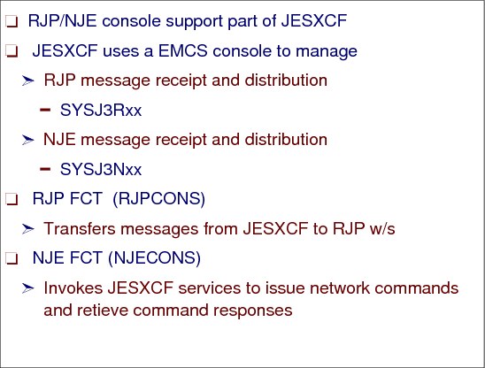
Defining RJP consoles
The CONSOLE statement TYPE=RJP defines RJP consoles. The RJP CONSOLE initialization statement is as follows:
CONSOLE,JNAME=name,TYPE=RJP,DEST=(msgdest,...msgdest),LL=nnn,
LEVEL=nn,SAVEMSG={YES|NO}
LEVEL=nn,SAVEMSG={YES|NO}
The parameters are:
SAVEMSG The SAVEMSG= parameter specifies whether messages should be received and spooled while the console is logged off.
DEST DEST= accepts MVS routing codes in addition to JES3 destination classes. DEST= specifies one or a series of message destinations which represent classes of messages you want sent to the specified RJP console. msgdest can be any set of MCS routing codes or JES3 destination classes. Single routing codes and JES3 destination classes are specified as a single value with commas separating the individual values. Ranges of MCS routing codes can be specified by including a dash between the start of the range and the end of the range. The JES3 destination class and MCS routing codes will be combined into a single set of message destinations used to determine what messages will be displayed on the console.
The workstation name is derived from the RJPWS initialization statement for an SNA workstation or the RJPTERM initialization statement for BSC. This workstation name serves as the userID for the workstation console. Users of the RJP console have to log on using this terminal ID and supply the same password.
14.8 RJP console commands

RJP console commands
The following commands may be used to affect message queueing to RJP consoles:
*SWITCH RJP01,RJP02 Redirects message traffic from one RJP console to another. This command must be issued from an operator (non-RJP) console. Only a single level of switch is allowed.
*SWITCH RJP01,NONE Stops message queueing to the target RJP console. This command must be issued from an operator (non-RJP) console.
*FREE RJP01 Frees all messages currently queued to the target RJP console.
*FREE Frees all messages currently queued to the RJP console from which the command is entered.
The following commands apply only to RJP consoles and the DLOG function:
•*I O command displays RJP console and DLOG status
•*F O command modifies RJP console and DLOG status
The *Z command sends a message to another RJP console or to a message destination.
Message IAT8618
To display the number of spooled messages queued to a signed off RJP console, enter:
*I D,T=RJP01
IAT8618 .. gives SPOOLED MSG=xx
IAT8618 .. gives SPOOLED MSG=xx
For signed on workstations, this command displays the number of messages queued in JES3 storage for the workstation. JES3 issues this message in response to an *INQUIRY command that requested the status of a BSC RJP line or workstation or a SNA RJP workstation. The designated line or workstation is not signed on. If SNA RJP is included in the message text, the specified workstation is an SNA RJP workstation; otherwise, the workstation or line is BSC RJP.
Message IAT8622
This message is issued in response to an *INQUIRY command that requested the status of a BSC RJP line or workstation or a SNA RJP workstation. The designated line or workstation is signed on.
*I D,T=RJP02
IAT8622 .. gives CHAINED MSG=xx
IAT8622 .. gives CHAINED MSG=xx
14.9 Displaying RJP consoles
Commands to display RJP consoles
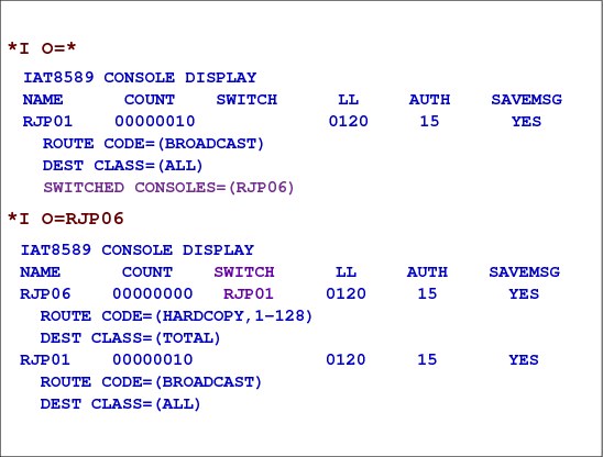
To display a RJP console status:
|
*I O=*
IAT8589 CONSOLE DISPLAY NAME COUNT SWITCH LL AUTH SAVEMSG RJP01 00000010 0120 15 YES ROUTE CODE=(BROADCAST) DEST CLASS=(ALL) SWITCHED CONSOLES=(RJP06) |
When displaying console RJP06 whose messages have been switched to console RJP01, RJP01 console status is also displayed:
|
*I O=RJP06
IAT8589 CONSOLE DISPLAY NAME COUNT SWITCH LL AUTH SAVEMSG RJP06 00000000 RJP01 0120 15 YES ROUTE CODE=(HARDCOPY,1-128) DEST CLASS=(TOTAL) RJP01 00000010 0120 15 YES ROUTE CODE=(BROADCAST) DEST CLASS=(ALL) |
14.10 NJE functions

Network job entry (NJE)
In JES, a facility which provides for the transmission of selected jobs, operator commands, messages, SYSOUT data, and accounting information between communicating job entry nodes that are connected in a network either by binary synchronous communication (BSC) lines, channel-to-channel (CTC) adapters, by System Network Architecture (SNA) connections, or by Transmission Control Protocol/Internet Protocol (TCP/IP or TCPIP).
Unit of work
An NJE transfer unit is a unit of work that is transmitted across the network. An NJE transfer unit can be either an NJE job or a nodal message record (NMR).
An job is a transfer unit that contains data to be processed at another node in the NJE network. It begins with a job header, is followed by data, and ends with a job trailer. The type of data contained in the NJE job further defines the type of the NJE job. The data between the job header and job trailer can be either SYSIN or SYSOUT data. An NJE SYSIN job is an NJE job that contains JCL for a job and may have one or more SYSIN data sets. An NJE SYSOUT job is an NJE job that contains one or more SYSOUT data sets. Each SYSOUT data set is preceded by a data set header.
A nodal message record (NMR) is a unit of work that begins with an NMR header and is followed by message text. The message text can be either a message or system command.
Functions of a node
A node is a system or complex that is defined to an installation. A node in the network can be another complex or system within a single location or it can be a complex that resides in a remote location. Each node that a complex can access must be identified to other complexes by a unique NJE node name.
|
Note: If a node uses SNA protocols, the node has two names:
– An LU name as defined to VTAM
– An NJE node name created during JES initialization processing
The NJE node name appears in job headers, data set headers, and NMRs.
|
Each node in the network can do the following with an NJE transfer unit:
•Transmit - The node packages the NJE transfer unit and transmits it to another node.
•Receive - The node recognizes the NJE transfer unit, receives, and stores it.
•Store-and-forward - The node accepts the NJE transfer unit, stores it, and schedules it to be forwarded to another node.
Types of nodes
NJE uses the following terminology for the nodes that comprise an NJE network.
•Originating Node is the node where the user submitted the request to transmit the data.
•Intermediate Node is a node that lies in the path of either the:
Originating node and execution node
Execution node and the destination node
It receives and transmits the NJE transfer unit to the next node in the path of the target node.
•Target Node is the node where a NJE job or NMR is received and will either be executed or be processed. The target node can be either a:
Destination Node - a node that receives and processes:
• An NJE SYSOUT job.
• A message contained in an NMR.
Execution Node - a node where:
• JCL contained in an NJE SYSIN job executes.
• A command contained in an NMR is processed.
Transmitting and receiving
Each node in the network has the capability of transmitting and receiving a network units of work. The node that sends the network unit of work can use either BSC, SNA, or TCPIP protocols. The type of networking protocol the home node uses to transfer the network stream is determined by the JES3 NJERMT initialization statement that defines the directly connected remote node. The receiving node can process the network job locally or can transmit the network stream to another node in the network.
Store and forward
If the originating node and the destination node are not directly connected nodes, path nodes are used to route the network stream to the destination node. JES3 adds the NJESF scheduler element to the network job to pass the network stream to the next node in the path of the destination node. The store and forward DSP prepares the network stream so that it can be sent to the next destination node using the proper networking protocol.
14.11 NJE units of work

NJE networking
Each node has the capability to:
•Send job streams to the other node.
•Send SYSOUT streams to the other node.
•Send commands to the other node.
Networking examples
If a user at NODEA submits a request to transmit a job to execute at NODEC, NODEA is the originating node. Input service at NODEA processes the user's JCL for the request and creates a network job.
Networking creates separate data sets to contain the different portions of the network stream and creates JDS entries to identify the data sets. Networking assigns the following names to each data set:
|
IATYNCN Defines the Nodal Message records (NMR).
IATYNJH Defines the job header information for the network stream.
IATYNDH Defines the JCL and/or SYSIN data for the job.
IATYNJT Defines the job trailer information for the network stream.
|
See Network Job Entry Formats and Protocols, SA22-7539 for additional information.
14.12 Transport protocols

Transport protocols
A network stream is transmitted across a connection that is initialized by a networking protocol. JES3 supports two networking protocols:
•SNA and BSC
The network is comprised of the home node and all of the remote nodes defined to the home node. Each node in the network is identified by a unique node name assigned to the node during JES3 initialization. A node can be a JES3 complex networking for both SNA and BSC to:
•Another JES3 complex
•JES2 complex
•VM RSCS complex
•VSE/POWER complex
•AS/400®
The type of protocol used to transmit the network stream is determined by the TYPE= parameter on the NJERMT statement that defines the directly connected remote node. If TYPE=BSC is specified on the NJERMT statement that defines the remote node, BSC protocols are used to transmit the network stream. If TYPE=SNA is specified on the NJERMT statement, SNA protocols are used to transmit the network stream. TYPE=TCPIP specifies a TCP/IP networking protocol. Since a node can be directly connected to more than one node, each JES3 node in the network has the capability of transmitting a network stream by using BSC, SNA, or TCPIP protocols.
14.13 BSC initialization statements
BSC definitions
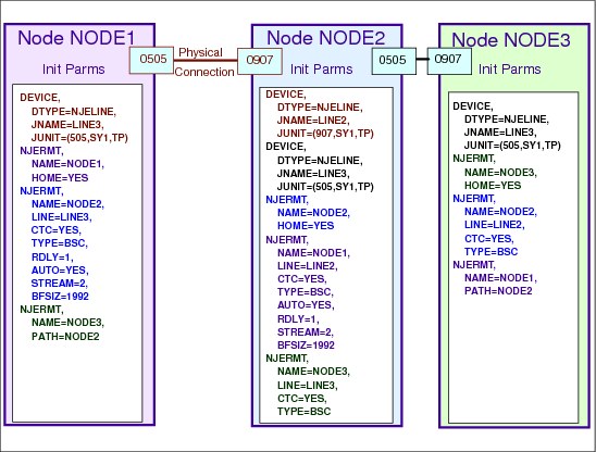
You must code a NJERMT statement for the home node (your node) and one for each remote node that will communicate with the home node.
All DEVICE statements with the parameter DTYPE=SYSMAIN specified must precede the NJERMT statement.
The JNAME parameter on a DEVICE statement that also includes a DTYPE=NJELINE parameter must match the LINE parameter on the NJERMT statement.
To transmit an NJE transfer unit to a complex other than the user’s installation (a remote node), the user issues a command or submits a job specifying a destination node name. The destination node can be either directly- or indirectly-connected to the originating node. In the network depicted in the figure, if NODE1 is the originating node, NODE2 is a directly-connected node to NODE1, and NODE3 is an indirectly-connected node to NODE1.
To transmit an NJE transfer unit from NODE1 to NODE3, NODE2 is required to do a store-and-forward function since there is not a direct physical connection defined between NODE1 and NODE3.
14.14 BSC line or CTC DEVICE statement for NJE

BSC line or CTC DEVICE statement for NJE
The following statements are the primary definitions for BSC lines and devices:
DTYPE= Specifies that a BSC line or a CTC connection for a network of nodes.
JNAME= Specifies a name of a BSC line or CTC connection. The first character of the 1-8 character name cannot be a slash (/). The variable linename must match the name you specify on the LINE parameter of the JES3 NJERMT initialization statement that defines your node.
JUNIT= Specifies information about the line or CTC connection. You must code the following parameters for the global. You must repeat these parameters for each local main that has access to the line and could become the global.
devnum - Specifies the device number (by 3-digit or 4-digit hexadecimal number). A slash (/) preceding the device number is not required.
main - Specifies the name of a main that has access to the line when the main is global. The variable main must match the name of the main that you define on a MAINPROC statement. Alternatively, a main name of *ALL can be used. Use of *ALL indicates that all mains in the complex have access to this line when the main is the global.
TP - Specifies the destination class that is to receive messages about this line. or connection.
14.15 NJERMT statement for NJE

BSC NJERMT statement
For BSC networking, the NJERMT initialization statement contains the following definitions:
NAME= Specifies a 1-to-8 character node name. No two nodes should have the same node name. The names that can be specified are:
•Node name
•Home name
HOME= Specifies whether this NJERMT statement defines the home node or a remote node. If it defines the home node, code YES. For all other nodes, omit this parameter or code NO.
LINE= Specifies the 1-8 character name of the line that connects the home node to the directly-connected remote BSC node defined by this statement. This name must match the name specified via the JNAME parameter on the DEVICE statement that defines the line. When the operator starts the line, he can override the name you have specified with this parameter. If you omit the LINE parameter, the operator must specify a line name when starting the line.
CTC= Specifies the type of connection between the home node and the directly-connected remote BSC node defined by this statement. For a node that is connected via a channel-to-channel (CTC) adapter, specify YES. For a node that is connected via a leased line or a dial-up line, omit this parameter or specify NO. This parameter is ignored when TYPE=SNA is specified.
RDLY= Specifies, in minutes, the amount of time that JES3 networking is to wait before it automatically restarts an interrupted line. Allowable values for mm are 0-99. Code this parameter on an NJERMT statement that defines a directly-connected remote BSC node.
STREAM= Specifies the number of concurrent data streams that JES3 networking is to transmit on one line between the home node and the directly-connected remote BSC node defined by this statement. STREAM=2 is not allowed for directly connected, remote BSC nodes, running RSCS under VM.
TYPE= Specifies the networking protocol to be used for communicating with a directly-connected remote node. Include this parameter only when defining a directly-connected remote node.
•BSC Specifies a BSC networking protocol.
•SNA Specifies a SNA networking protocol.
AUTO= Specifies, for a directly-connected remote BSC node, whether JES3 is to automatically restart the line to the node if the remote node interrupts transmission. Specifying YES causes JES3 to automatically restart the line. If you specify NO or omit this parameter and the remote node interrupts transmission, the operator must restart the line. Code this parameter on the NJERMT statement that defines a directly-connected remote BSC node.
PATH= Specifies the name of the first node in the path to an indirectly-connected node. Code this parameter on the NJERMT statement that defines the indirectly-connected node. If you omit this parameter, JES3networking assumes the home node and the remote node are directly connected.
BFSIZ= Specifies the buffer size to be used for communication with the directly-connected remote BSC node defined by this statement. The system programmer at the remote node must specify the same buffer size as you specify. Do not specify a buffer size of less than 400 bytes. The maximum buffer size allowed is the size of the spool buffers (specified via the BUFSIZE parameter on the BUFFER statement) minus 46.
14.16 BSC - NJE commands
BSC commands
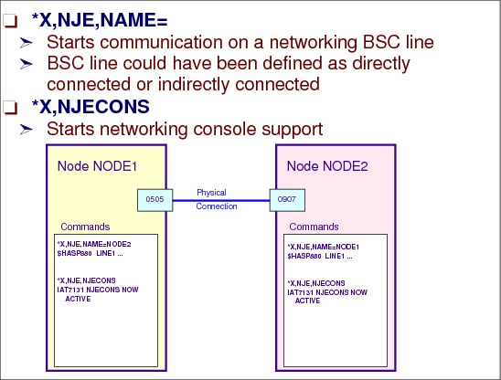
Use the *X NJE command to start communication on a networking line that directly connects your complex to a remote node.
You must use this command after JES3 initialization to start communication on a line that directly connects your node to a remote node before you can transmit to or receive data from that node or from indirectly connected nodes whose path is through that node.
If more than one line connects your node with a remote node, you can also use this command to start the additional lines as they are needed.
Use the *X,NJE command to specify I/O operations across the BSC NJE line and only for BSC/NJE networking.
NJECONS DSP
Use the *X NJECONS command to start networking console support DSP. After JES3 initialization and before you can send or receive commands or messages from nodes in your network, you must use this command to start networking console support.
JES3 starts networking console support. You can now send and receive messages and commands to or from any other node in the network.
IAT7131 NJECONS NOW ACTIVE
14.17 NJE command and message flow
NJE consoles
JES3 networking console support is handled by the NJECONS DSP (module IATCNNJ). This DSP is called and canceled by the operator.
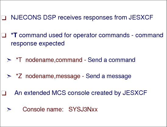
NJECONS DSP
The NJECONS DSP processes nodal message records (NMRs), which contain network commands or messages. The NMRs may be received from or sent to other nodes in the network.
The NJECONS DSP mainline performs initialization, routing and termination functions. The DSP initializes the network console queue (NCQ) and anchors it from the TVT. Routines in NJECONS DSP maintain also the network pending command queue (NPC). When a remote node sends a command to this node, the command NMR is chained from an NPC entry which will represent the NJE command. Console support is established for the NJE command instance by invoking JESXCF with a unique console name associated with the new NJE command instance. The command is issued. When a response is issued for the command, it is routed to JESXCF which in turn will notify the NJECONS DSP that a command response is available. The responses are retrieved from JESXCF. NJE command response entries are created and routed back to their origin for each message received from JESXCF.
NJE EMCS console
The name JESXCF assigns to the NJE extended MCS console is SYSJ3Nxx with a KEY=xcfgroupname. The NAME parameter on the NJERMT statement that defines HOME=YES is the default for the xcfgroupname parameter on the OPTIONS statement.
The xx in the SYSJ3Nxx console name is an internally generated number that starts with 01. For example, suppose a command, CP SM RSCS CMD WTSCPLX3 *I Q, is sent from VM to JES3. When the command is received at node WTSCPLX3, the following occurs:
•The command NMR is chained from an NPC entry which will represent the NJE command. Console support is established for the NJE command instance by invoking JESXCF with a unique console name associated with this NJE command instance. The same console name is used to build Console Destination Block (CNDB) for use on the INTERCOM macro. The command is then issued with the INTERCOM macro. When a response is issued for the command, it is routed to JESXCF which in turn will notify this DSP that a command response is available.
•The CNDB (the console destination block or CNDB encapsulates console routing information) for the INTERCOM has a unique command and response token (CART) value assigned identifying the command instance and SYSJ3N01 as the console. Later, the CART value is used to filter the command response from the SYSJ3N01 console's message queue. Once the response is retrieved from the console, it is sent back through the network to the remote node.
•DSI processing switches the console name from SYSJ3N01 to the next available console name (e.g. SYSJ3N02).
*SEND (*T) command
Use the *T command to send selected commands to other for processing.
You can use this command to modify or display the status of jobs submitted at your node and sent to another node for processing.
Syntax: *T nodename,system-commands
Note: The comma between nodename and system-commands is required.
*MESSAGE (*Z) command
Use the *Z command to send a message to one or more consoles on the system or the NJE network. You can direct messages to a specific console or to a group of consoles designated by a common MCS routing code or JES3 destination class.
Syntax:*Z {ALL | con | node | msgdest},text
Using JES3 to authorize commands from NJE
JES3 allows only *INQUIRY and *MODIFY commands to be entered through NJE unless an installation overrides the JES3 authorization processing by using IATUX35 exit or RACF.
The *I commands allowed from NJE are:
•*I Q,N
•*I B
•*I J,E
The *F commands allowed from NJE are:
•*F J,C
•*F J,CP
•*F J,CO
•*F J,H
•*F J,R
14.18 Dynamic SNA NJE node definitions

Adding SNA nodes dynamically
Use the *F NJE command to:
•Dynamically add a directly-connected node to your network at your home node.
•Dynamically add an indirectly-connected node to your network.
•Dynamically add an alias of your home node to your network.
•Dynamically delete a node or alias from your network.
•Reset the lines connecting your node to a specific remote node when your node has abnormally ended communication on the line
•Place jobs scheduled for transmission to a specific remote node in operator hold status
•Release a remote node from hold status
|
Note: You cannot dynamically add or delete your installation (the home node) to the network.
|
Do not use the *F NJE command to change the type of protocol, from SNA to BSC, for dynamically added nodes. Be careful when using the *F NJE command to change the type of protocol from SNA or TCP/IP to BSC. In particular, a device with DTYPE of NJELINE must be available for this BSC node to use. If such a device does not exist, it must be added with a hot start with refresh before you can use the modified BSC node. You cannot delete an active adjacent BSC node from your installation. An active node is a node currently transmitting to or receiving data.
14.19 Symbols in commands in exits
Using system symbols with NJE commands
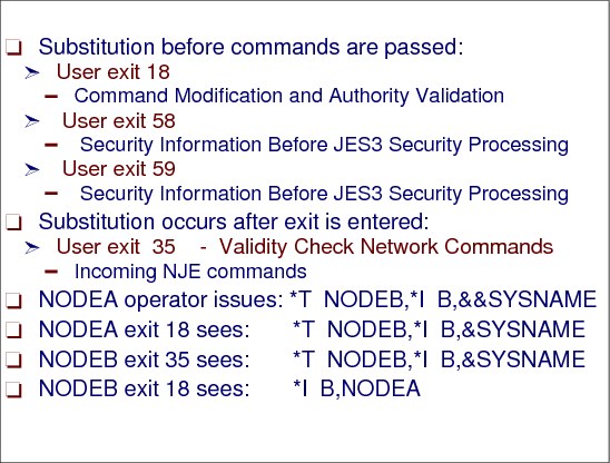
When using JES3 exits for command processing with symbols in the command, symbolic substitution takes place as follows:
•For JES3 commands, substitution takes place before exits 18, 58 and 59 are entered.
•For NJE commands, substitution takes place after exit 35 is entered.
In the example, for sending commands via NJE you must use a double ampersand with symbolic symbols. When the system finds two consecutive ampersands at the beginning of a valid symbol, it removes the first ampersand and keeps the second ampersand in place. A subsequent process can then substitute text for the symbol in later processing, or the second ampersand can remain as a literal character.
So if you route a command to another node in a network, use double ampersand (&&) notation to cause substitution to occur on the receiving node.
However, since exit 35 is entered before substitution occurs, be aware that the command may have the symbol still there.
14.20 BSC NJE commands to Other Nodes

NJE commands to other nodes
This figure has some examples of NJE commands and NJE commands to other nodes in the NJE network and the responses to the commands.
•Use the JES3 *I NJE command to display the status of the networking nodes and communication lines.
•Use the MCS ROUTE command to direct a command to one or more systems in a sysplex for processing. You can direct a command to:
– All systems in the sysplex
– A subset of the systems in the sysplex
– One system in the sysplex.
|
Note: In the example, the MCS ROUTE command could be used to send operator commands from JES3 global running on SC50 main to another JES3 global main running on SC43 because the two JES3 complexes were running in the same sysplex.
|
14.21 z/OS Bulk Data Transfer (BDT)
z/OS BDT and JES3 SNA NJE
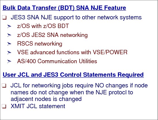
The BDT systems network architecture (SNA) NJE feature (a licensed program) allows z/OS JES3 users to transmit jobs, output (SYSOUT), commands, and messages from one computer system to another within a SNA network. Any of the following systems can participate in the network: z/OS JES2, z/OS JES3 (with BDT), VM/SP (with RSCS Networking), VSE/Advanced Functions (with VSE/POWER) and AS/400 Communication Utilities.
BDT runs in its own address space. A JES complex may have one or more BDT address spaces. Each processor in the complex may have one or more BDT address spaces. A complex with multiple BDT address spaces is called a poly-BDT complex. You must decide whether you want to set up such a complex. A poly-BDT complex is beneficial during testing, as a way to separate testing from production work.
Defining BDT to MVS
BDT operates under the control of MVS and therefore requires the following MVS definitions:
1. You must define BDT as a secondary MVS subsystem by creating an entry in an IEFSSNxx member of SYS1.PARMLIB.
2. You must specify MVS system parameters in an IEASYSxx member of SYS1.PARMLIB.
3. You must give authorized program facility (APF) authorization to SYS1.BDTLIB, the BDT module library, by updating SYS1.PARMLIB member IEAAPFxx.
4. If you are installing BDT in a JES3 complex, you will have to add several statements containing BDT-related information to the JES3 initialization stream. The statements are CONSOLE, SYSID, and, for SNA NJE customers, NJERMT.
Defining BDT to VTAM
BDT runs as a VTAM application program, requiring several VTAM definitions:
1. You must define BDT as a VTAM application program on the APPL definition statement. One APPL statement is required for each type of node your system will have, that is, one APPL statement for a file-to-file node and one APPL statement for a SNA NJE node.
2. You must define each remote node as a VTAM cross-domain resource.
3. You must define session parameters to VTAM by creating VTAM logon mode table entries.
Allocating BDT SNA NJE data sets
With MVS and VTAM definitions complete you can start work on BDT itself. Your first task is to allocate data sets that are used during BDT SNA NJE operation:
1. You must allocate a data set to contain the BDT initialization stream. Later you will put initialization statements into this data set and then specify its name on the procedure that the operator invokes to start BDT.
2. You must allocate a data set to contain the BDT work queue, in which BDT places jobs waiting to be processed. Sample BDT SNA NJE feature only JCL procedure:
//BDT43 PROC
//* ***********************************************************
//* THIS PROCEDURE MAY BE USED TO INITIALIZE MVS/BDT WITH *
//* THE FILE TO FILE FEATURE (FTF), NJE FEATURE, OR BOTH. *
//* IT IS MEANT AS AN EXAMPLE ONLY. THE DATA SET NAMES *
//* MAY BE MODIFIED AS REQUIRED. ALL DATA SETS MUST BE *
//* CATALOGED PRIOR TO INVOCATION. *
//* ***********************************************************
//BDT EXEC PGM=BDTINTK,REGION=5000K,TIME=1440
//* STEPLIB DD DISP=SHR,DSN=SYS1.SBDTLIB
//BDSPOOL DD DISP=OLD,DSN=SYS1.SC43.BDTSPACE
//CRSPOOL DD DISP=OLD,DSN=SYS1.SC43.BDTSPACE
//BDTOUT DD SYSOUT=A
//SYSABEND DD SYSOUT=A
//BDTABEND DD SYSOUT=A
//BDTIN DD DISP=SHR,DSN=SYS1.PARMLIB(BDTSNAT9)
Creating a BDT initialization stream
To define the environment in which BDT will operate each time it is started you must code initialization statements. You can specify the amount of main storage BDT will use, the names of nodes in the network, the pacing rate for communication between nodes, and many more parameters. You identify the data set containing the initialization statements in the BDT start procedure.
The IBM-provided initialization statements are in SYS1.SBDTSAMP data set.
XMIT JCL statement
Use the XMIT JCL statement to transmit records from an MVS node to a JES3 node, a JES2 node, a VSE/POWER node, a VM/RSCS node, or an AS/400 node.
JES3 passes the jobs to BDT, which have to enter the network to adjacent SNA NJE node. If necessary, the network jobs can be routed through intermediate systems (store and forward) to reach their destination.
When writing new JCL, IBM recommends using the XMIT JCL (//name XMIT form) since this statement is not dependent on using a particular JES subsystem. In addition, the XMIT JCL is preferred because it allow transmission of records that a //*ROUTE XEQ, /*ROUTE XEQ or a /*XEQ statement does not allow.
14.22 z/OS BDT options

JES3 BDT and networking nodes
This figure shows the possible combinations of communication from JES3 SNA NJE and BDT file-to-file (FTF) to other networking systems. JES3 BDT runs in its own address space which can be on either the global or local processor.
BDT address space
The MVS/Bulk Data Transfer (BDT) Facility is a subsystem of MVS that runs under its own address space on any main in the complex. A complex can have one or more z/OS BDT subsystems in its configuration.
BDT file-to-file
The z/OS BDT Facility is available as a program product of the MVS system product. z/OS BDT is available in two releases. z/OS BDT Version 1 allows the installation to transfer (copy) data sets from its original location to a new data set in the same or a new complex. This is the file-to-file function of z/OS BDT.
14.23 BDT SNA NJE processing
JES3 BDT node to node transaction
In a JES3 complex, an z/OS BDT subsystem can run on a global or a local. JES3 uses two function control tables (BDT FCT and BDTCOMM FCT) that provide the interface between JES3 and z/OS BDT. Collectively, these FCTs are called the JES3/BDT communications interface.
This figure is an overview of how a BDT transaction takes place from the creation of the SYSOUT file to the transmission by BDT to another node.
User SYSOUT
A user can create a network job to send one or more SYSOUT data sets (DEST=node) to one or more nodes. Each SYSOUT data set is represented by one or more data set headers. The data set headers indicate:
•The node where the SYSOUT data set should be processed
•Processing options for the SYSOUT data set
A shuttle BDT Subsystem Interface Data (BSID) area is associated with each z/OS BDT address space that is defined in the complex. JES3 uses the shuttle to send requests to the specified z/OS BDT subsystem. The BSID contains a data area where JES3 places the request. To send a BSID to z/OS BDT, JES3 issues a JSERV macro TYPE=RESP. The subsystem communication routines that process the JSERV macro, place the BSID in the shuttle staging area and pass it through the subsystem interface to the specified z/OS BDT subsystem.
14.24 BDT - SYSOUT received at destination node

BDT - SYSOUT received at destination node
This figure shows what happens when the SYSOUT arrives at the receiving node.
NJERDR DSP
The data set containing the stream is received by the z/OS BDT subsystem. z/OS BDT decompresses the data and writes the data to spool as a single data set. z/OS BDT spins off the data set with a destination of NJERDR. The data set is queued to a NJERDR DSP or a NJERDR DSP that is waiting is posted to indicate a data set was received and is ready to be processed.
The NJERDR DSP, module IATNTNR, passes records containing a Record Identifier (RID e.g. SYSIN or SYSOUT) and data to module IATNTJS. Module IATNTJS removes the RID from the spool record. For a network SYSOUT stream, module IATNTJS creates at least four data sets. Each data set contains either:
•Job header information
•Data set header information
•File description blocks that contain the addresses of the SYSOUT data sets on spool
•SYSOUT data
•Job trailer information
To process the data, module IATNTNR obtains buffers (JDS, JDAB, JCT, AND JMR) that will be used to create a network job at this node to process the network stream.
14.25 BDT transmission streams

Contents of an NJE Job
An NJE job contains either SYSIN or SYSOUT data and the control records used to identify the data being transmitted A node uses these control records to transmit an NJE job:
•A job header: An NJE job must contain a job header to indicate the start of the job. The NJE job can contain either SYSIN or SYSOUT data.
•The job header may include several sub-sections depending on the NJE product where the NJE job originated. All NJE products require a prefix section and a general section in the job header.
•A data set header: A data set header is required if the data is SYSOUT or optionally SYSIN data. If the NJE job contains a job and a SYSIN data set, a record characteristics change section (RCCS) may be included in the NJE job to indicate a change in the length of the records.
•A job trailer: A job trailer indicates the end of an NJE job. The job trailer is divided into several sections depending on the networking facility where the NJE job originated. All networking facilities require a job trailer prefix section and a job trailer general section.
The home node packages the data to be transmitted in a network stream. JES3 recognizes two types of network streams: a network job stream and a network SYSOUT stream. A network job stream and a network SYSOUT stream both include a job header and trailer. The data sets for the data streams have their own spool space (DSISO) and can be purged following transmission.
The data streams are compressed and their format follows Network Job Entry Formats and Protocols, SA22-7539 definitions.
14.26 XMIT JCL statement

XMIT JCL statement
Use the XMIT JCL statement to transmit records from an MVS node to a JES3 node, a JES2 node, a VSE/POWER node, a VM/RSCS node, or an AS/400 node.
Syntax:
//[name] XMIT parameter[,parameter]... [comments]
Parameters:
– DEST=nodename[.vmuserid] - Identifies the destination for all following records until a delimiter stops transmission of the records.
– DLM=delimiter - Specifies a delimiter to stop the transmission of records.
– SUBCHARS=substitute - Specifies a substitute for internal reader control statements. (JES3 only)
Use of XMIT JCL Statement in a JES3 System allows network transmission of the job. A //*ROUTE XEQ statement can also be used to transmit records from a JES3 node. Because an XMIT JCL statement allows transmission of records that the //*ROUTE XEQ statement does not allow, use XMIT JCL statements rather than //*ROUTE XEQ statements.
The sending system does not process or check the records for validity except when the JCL is processed by an internal reader (such as with TSO/E submit processing). In this case, the system recognizes /*EOF and /*DEL as internal reader control statements and errors can occur on the sending system if /*EOF or /*DEL are included in the XMIT JCL stream.
14.27 Using XMIT statement
Using XMIT JCL
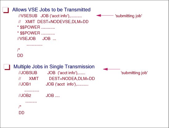
For example, a JOB statement for the receiving node must immediately follow a //*ROUTE XEQ statement. This requirement means that a //*ROUTE XEQ statement cannot be used to transmit records beginning with $$POWER control statements to a VSE node; however, an XMIT JCL statement can transmit such records.
NJE jobs contain two JOB statements. The first JOB statement is used to route the work to the remote node. The second JOB statement is the statement used to process the work. The JES3 //*ROUTE XEQ or //XMIT statement have their first JOB statement verified at the submitting node and their second JOB statement verified at the execution node.
The system builds network job header and trailer records from information on the JOB statement and any //*NETACCT statements, if included, preceding the XMIT JCL statement. Then the system transmits all the records between the XMIT JCL statement and a delimiter statement.
The records can consist of a job input stream, an in-stream DD * or DD DATA data set, or any job definition statements recognized by the destination node. If the records are a job input stream, and the destination node can process the JCL, the transmitted input stream is executed at the destination node. The records must be 80 characters long.
The records end when the system finds one of the following delimiters:
•/* in the input stream, if a DLM parameter is not coded on this XMIT JCL statement.
14.28 XMIT JCL statement rules
XMIT rules
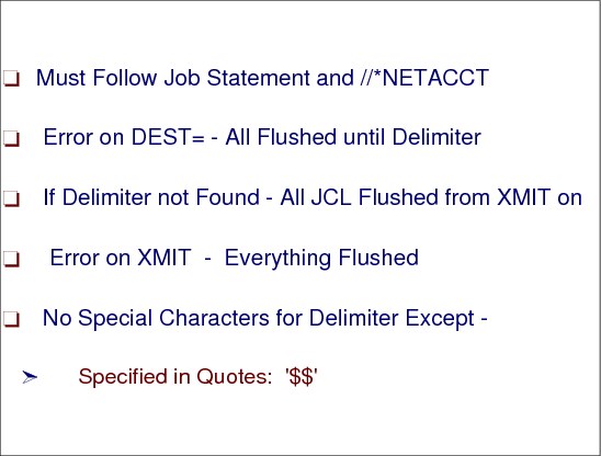
This figure shows the rules that apply when using the XMIT JCL statement.
Use the DEST parameter to specify a destination for the following input stream records. The DEST parameter can send the records to a node or, for a node that is a VM system, to a guest system running on the virtual machine.
If the delimiter is not two characters, the system terminates the job and does not transmit any records. If the specified delimiter contains any special characters, enclose the delimiter in apostrophes. In this case, a special character is any character that is neither alphanumeric nor national ($, #, @).
If the delimiter contains an ampersand or an apostrophe, code each ampersand or apostrophe as two consecutive ampersands or apostrophes and enclose the delimiter in apostrophes. Each pair of consecutive ampersands or apostrophes counts as one character.
If the system finds an error on the XMIT JCL statement before a specified DLM parameter, all jobs in the batch are flushed.
14.29 NJE JOB received at originating node

NJE job received at originating node
When a user’s job requested a network job to be transmitted, JES3 input service creates for the submitting job a JCT with the CI, MAIN, OUTSERV, and PURGE scheduler elements. The CI and MAIN scheduler elements are marked complete so that OUTSERV and PURGE are the scheduler elements that will processed.
For a network SYSOUT stream, the CI and MAIN SEs have already been marked complete (due to the execution of the job) and the OUTSERV and PURGE scheduler elements will complete the processing required to transmit the network stream. If the network stream will be forwarded to another node, JES3 creates a NJESF, OUTSERV and PURGE scheduler element.
JSS scheduling
The JES3 job segment scheduler (JSS) adds a job to the output service queue when it determines all previous SEs for the job are complete. JES3 places the job on the appropriate output service queue and:
•Indicates that normal or spin-off processing should be performed for the network job
•Posts the OUTSERV FCT
14.30 JES3/BDT NJE outbound job processing
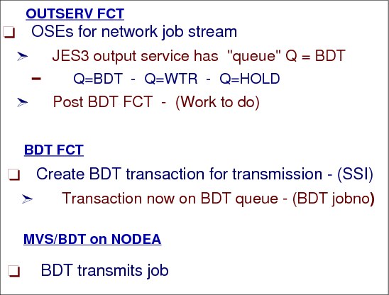
JES3/BDT SNA NJE outbound job processing
When the multifunction monitor (MFM) dispatches the OUTSERV FCT for processing, the output service driver module IATOSDR is invoked. The output service driver locates a job and creates output service elements (OSEs) to represent the data sets in the network stream.
An OSE must be built for each part of the network stream to be transmitted across the network. If necessary, an OSE for the job header, an OSE for the job trailer and an OSE for the data set header, if the data is SYSOUT data. Output Service groups the OSEs that represent the network stream together. Since the OSE that represents the data was built before the OSEs for the job header, data set header and job trailer, IATOSBP makes a copy of the OSE created by IATOSDO so that all the OSEs for the network stream are grouped together.
BDTCOMM FCT
After building the necessary control blocks needed for the SNA networking job, the BDTCOMM FCT is posted. The JES3/BDT communications interface notifies the z/OS BDT subsystem at the home node that the JES3 job queue contains a network job that should be transmitted to the destination node by using SNA protocols. Module IATOSBM processes a TYPE=GET request to obtain the OSEs.
Module IATBDCI creates a transaction to send to the z/OS BDT subsystem. Module IATBDCI issues a JSERV to send the data set information in a staging to the BDT queue.
NODEA BDT transmits the job.
14.31 SNA NJE job received at execution node

SNA NJE job received at execution node
The transmitting node sends each record in the network stream. BDT in the receiving node reads the record and writes the decompressed record to JES3 spool. All the transmitted records are placed in a single spool data set. The data set contains all the components of the network stream: the job header, the data set header if the data is SYSOUT, the data and the job trailer. Each record in the data set contains a record identifier (RID) which is followed by the data in the record. A RID is used by networking to identify the contents of the record.
Spinoff data set
When the entire network job stream is processed, BDT spins off the data set with a destination of NJERDR. The data set is queued to a NJERDR DSP or a available NJERDR DSP that is waiting is posted to indicate a data set was received and is ready to be processed.
Module IATNTNR, the NJERDR DSP driver, requests work from output service by indicating in a writer selection parameter area (WSP) that a SYSOUT data set destined for an external writer named NJERDR is required. The NJERDR uses the IATXOSPC macro service to request a data set from output services and calls 'Networking Job/SYSOUT Receive Module' IATNTJS. IATNTJS creates a “utility” job to process the “spin off” network stream at this node.
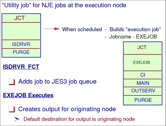
NJE utility job
The “utility” job’s scheduler elements are ISDRVR and PURGE for jobs at destination node and NJESF, OUTSERV, and PURGE for SNA and TCPIP remote destination jobs. Remote BSC jobs have NJESND scheduler element instead of OUTSERV.
14.32 JES3 processing for a received NJE job
JES3 processing for a received SNA NJE job
When the “utility” job’s ISDRVR scheduler element job is scheduled, the transmitted network job is read and passed through input service. Input service adds the job as a “normal” job to the execution node’s JES3 job queue with scheduler elements CI, MAIN, OUTSERV, and PURGE.
EXEJOB job
When the job finally executes and creates SYSOUT output, the default destination for the SYSOUT data is the originating node. The OUTSERV scheduler element of the EXEJOB job will then send the output to the originating node.
14.33 OUTSERV for NJE job at execution node
OUTSERV for an NJE job at execution node
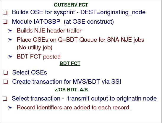
When the OUTSERV FCT is scheduled to build OSEs, the output service driver, IATOSDR o completes building the OSEs for network jobs (both “job stream” and “SYSOUT stream” work).
OSE construction
An OSE must be built for each part of the network stream to be transmitted across the network. If necessary, module IATOSBP builds an OSE for the job header, an OSE for the job trailer and an OSE for the data set header, if the data is SYSOUT data. Output Service groups the OSEs that represent the network stream together.
After module IATOSDR has built the necessary control blocks needed for the SNA networking job, the BDTCOMM FCT is posted. The JES3/BDT communications interface routine notifies the z/OS BDT subsystem that the JES3 job queue contains a network job that should be transmitted to the destination node by using SNA protocols.
BDT FCT
A routine in module IATBDCI (BDT FCT) is invoked by the JES3 dispatcher (multifunction monitor - MFM) when the FCT is posted. Processing in module IATBDCI uses the IATXOSBM TYPE=GET macro to search the output service writer RESQUEUE chain for a network job that requires SNA protocols. Module IATBDCI creates a transaction to send to the z/OS BDT subsystem and issues a JSERV to send the information in a staging area to BDT address space. BDT then transmits the network job by selecting the transaction from its queue.
14.34 Output received at originating node

Output received at originating node
At the originating Node, BDT receives the SYSOUT network job and writes the received data to JES3 spool. The spool data set for the received network job is created with an external writer name of NJERDR. JES3 output service OSE construction posts the NJERDR FCT once an OSE is build for the network job’s spool data.
NJERDR FCT
The NJERDR FCT selects the OSE and creates a utility job. When a network stream that contains a SYSOUT data set is received, module IATNTJS builds a job that will process the SYSOUT data. This job has NJESF, OUTSERV, and PURGE scheduler elements.
NJESF DSP
The NJESF DSP prepares a SYSOUT stream for local printing or store-and-forward through a communication link. It also prepares a job stream for store and forward via a BSC or SNA link.
According to the networking specifications, SNA data transmission is required to use compression to reduce the length of records for transmission by removing blanks and duplicate characters. Compaction (reducing the length of records by representing certain 8-bit characters with only 4 bits) is optional and is controlled by NJE and SNA protocols.
14.35 Output processing at originating node

Process output at originating node
After receiving a network job’s SYSOUT stream from the execution node JES3 has built a “utility” job with NJESF, OUTSERV, and PURGE scheduler elements to process the network job’s output.
JES3 networking creates “utility” jobs with the NJESF scheduler element for the following types of NJE streams received from other nodes:
•job streams to be forwarded through BSC, SNA or TCPIP nodes.
•SYSOUT streams to be forwarded through BSC, SNA or TCPIP nodes.
•SYSOUT streams to be processed locally.
NJESF DSP
The NJEFS DSP, once scheduled, prepares the network job for the next scheduler element in the “utility” job. For SYSOUT streams for local processing it updates the JDS in preparation for the OUTSERV DSP.
All of the data set headers for this stream are in a single spool file. Any SYSOUT data set within the stream may be preceded by one or more data set headers. the destinations for these multiple data set headers can be mixed, i.e. local, BSC, SNA and TCPIP destinations can all exist in a single received stream.
NJESF DSP processing for the various destinations is as follows:
•Data sets for local processing at this node - A JDS entry is built from the information in the data set header. if a data stream section exists in the data set header, and it contains scheduler work block (SWB) data, the SWB data are written to spool.
•Data sets destined for a remote node through a BSC link - First, the data set header is compressed and written to spool. The SYSOUT data set itself is compressed and written to spool in the same file as the data set header. A skeleton JDS entry is then built to represent the compressed data, and added to the JDS chain.
•Data sets destined for a remote node through a SNA or TCP/IP link - SNA NJE streams are processed through the z/OS BDT product where as TCP/IP/NJE streams are processed through NETSERV interface. First, the data set header is written to spool in its own file. A skeleton JDS entry is created for the data set header and added to the JDS chain. An entity name is built to represent the sysout data set. If a JDS entry for the SYSOUT data set has not previously been built, it is built at this point and added to the JDS chain.
•Store-and forward job streams processing - The JDS entries for the “utility” job's input files are read. The job's scheduler element structure is changed, if necessary, to match the destination type (i.e. NJESF/NJESND for BSC and NJESF/OUTSERV for SNA and TCPIP). The DSP cleans up and returns if the destination is through SNA/TCPIP node. For BSC, the job header, JCL data, and job trailer are compressed and written to spool in separate files. Skeleton JDS entries are built for these files and added to the JDS chain. control is then passed back.
14.36 JES3/BDT SNA NJE transmission summary

Transmission summary
This figure is a summary of the process of sending a SNA NJE job from an originating node to execute on the execution node and the SYSOUT coming back to the originating node to print that was discussed in the previous visuals.
14.37 z/OS BDT network streams and BDT group identifier
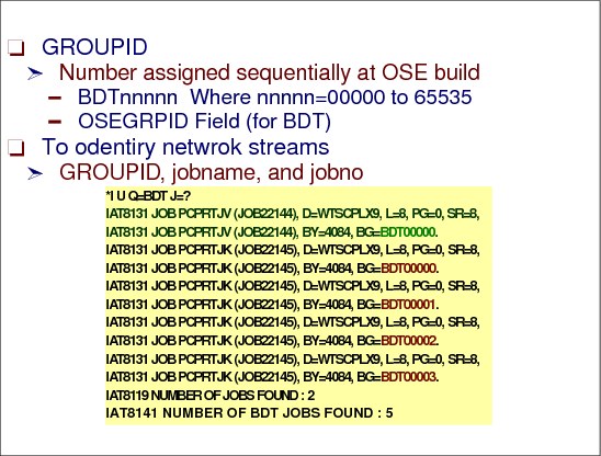
BDT network streams and BDT group identifier
Each JES3 job is identified by a JES3 number and a groupid. In the box below,JES3 JOB13 has one networking job (groupid BDT00000) and JOB14 has four networking jobs (groupids BDT00000, BDT00001, BDT00002, and BDT00003). Each JES3 networking job/SYSOUT stream running in BDT has a different z/OS BDT group number. In the table below, JOB13 and JOB14 indicates each networking job/SYSOUT stream as it is identified in z/OS BDT.
|
JOB13 JOB14
BDT00000 BDT00000 BDT00001
BDT00002 | BDT00003 |
After the job is placed on the z/OS BDT job queue, z/OS BDT sends a transaction notification BSID to the JES3/BDT Communications Interface (IATBDCI). This BSID is a queued response BSID. After receiving that transaction notification BSID, IATBDCI issues an Output Service BDT/TCP Manager IATXOSBM macro PUT request. This PUT request, containing indicators in the Output Service BDT/TCP Parameter List (IATYOSB) indicates that the file work has been queued on z/OS BDT (field OSEBFLG2 is set to OSEBQUED). T he IATXOSBM macro processing in IATOSBM module updates the OSEs pertaining to that job to indicate that the job has been placed on the z/OS BDT queue. The OSE is also updated with the BDT job number. IATOSBM uses the jobname and groupid to retrieve the Resident Job Queue Table entry (RQ) for the job. IATOSBM then returns control to IATBDCI.
14.38 Using JES3 DSISO for SNA NJE output data sets
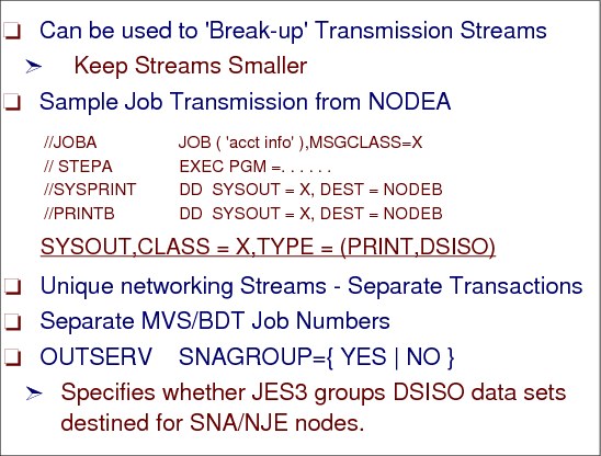
Using JES3 DSISO for SNA NJE
To make transmission streams smaller, use DSISO SYSOUT classes for processing of SYSOUT to other nodes. On JES3 (Output Service Defaults and Standards) initialization statement you can specify:
SNAGROUP= {YES | NO}
Specifies whether JES3 groups DSISO data sets destined for SNA/NJE nodes.
YES - Specifies that JES3 group DSISO data sets, if possible, which are destined for SNA/NJE nodes. Specifying YES allows the receiving node to assign a single job number to a group of data sets that were produced by one job at the originating node.
Specifying SNAGROUP=YES also causes JES3 to always group non-spin-off DSISO data sets (TYPE=DSISO specified on the SYSOUT initialization statement for the SYSOUT class). However, spin-off data sets, such as those produced by specifying FREE=CLOSE in the JCL, are sent separately because they are sent when the data set is closed rather than at the end of the job.
|
Note: Specifying SNAGROUP=YES prevents JES3 from releasing spool space used for DSISO data sets until all of the job's data sets have been sent to the specified node.
|
NO - Specifies that JES3 send DSISO data sets destined for SNA/NJE nodes as separate data sets. Specifying SNAGROUP= NO allows JES3 to release spool space as soon as a data set is sent.
14.39 Using DSISO for SNA NJE

Using DSISO
This is the example from the last figure after the OSEs have been created. The 3 OSEs would be processed separately. After all SYSOUT data sets have had their SYSOUT OSEs built for a job, module IATOSDR calls IATOSBP, supplying a pointer to a RESQUEUE indicating the job that is being processed and a pointer to the chain of SYSOUT OSEs (built by IATOSDO) for the current job. The head pointer to the chain of in-storage SYSOUT OSEs for this job is in IATODDR (location OSDRSECH). IATOSBP obtains working storage for building the job header, data set header and job trailer.
|
Note: If CLASS=X was not a DSISO class, then there would be one transaction created and one transmission stream.
|
14.40 BDT initialization definitions
BDT initialization definitions
To define the environment in which BDT will operate each time it is started, the system programmer must code initialization statements. The system programmer can specify the amount of main storage BDT will use, the names of nodes in the network, the pacing rate for communication between nodes, and many more operational characteristics. BDT initialization statements are similar in function to JES3 initialization statements. BDT reads these initialization statements during each warm or cold start of BDT.
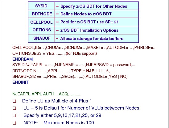
Initialization statements:
CELLPOOL A cell (sometimes called a storage cell) is another name for the main storage that is defined by a CELLPOOL statement. A cell pool is a group of cells that are related by the fact that BDT uses them for the same purpose.
A subsystem with only a SNA NJE node requires 12 different cell pools. CELLPOOL statements must be first in an initialization stream.
OPTIONS You can use the OPTIONS statement to specify operating characteristics of the home BDT subsystem.
SYSID The SYSID statement specifies the name of the home SNA NJE node. It also provides the application name and password that identify each node to VTAM.
BDTNODE BDTNODE TYPE=NJE specifies that the home and remote BDT nodes may send and receive only SNA NJE jobs and SYSOUT. This parameter corresponds to the BDT SNA NJE feature for JES3 installations.
1-100 BDTNODE statements (home and remote combined) per initialization stream.
SNABUF Use the SNABUF statement to allocate storage for data buffers. Each BDT subsystem uses data buffers to send data to and receive data from other BDT subsystems. You must define the size of these buffers and the number that BDT is to allocate. You may define several different sizes. You must ensure that each buffer size you define matches the size of an VTAM request unit (RU). BDT allocates these buffers from subpools 2, 3, 4, or 5.
SNA NJE transfers-- VTAM APPL definition statement
BDT is an VTAM application program. If BDT is to handle SNA NJE transfers, you must define BDT to VTAM as a SNA NJE node by coding an VTAM APPL definition statement:
name The label on the APPL statement must match the name on the NJEAPPL parameter of the BDT SYSID statement.
AUTH=ACQ You must code AUTH=ACQ to allow the BDT application to establish sessions using the VTAM SIMLOGON macro.
EAS=n Specify a value for n that is equal to the anticipated number of concurrent sessions that this node will have with all other BDT nodes. SYS1.SBDTSAMP contains a samples.
Virtual logical units
To achieve concurrent data transfer, BDT multileaves, over a single session, the data for each active transfer by splitting the session into "subsessions" known as virtual logical units (VLUs). A VLU is a logical path between two nodes that represents one user of a session between BDT nodes. Each active transfer is considered to be a user of one VLU.
For each session, BDT always requires one VLU for communicating control information. The other VLUs transfer the data.
For each JES3 SNA NJE session, 28 data transfer VLUs are possible. Of the 28 possible VLUs in a session, one node can schedule 14 (7 for sending jobs and 7 for sending output) and the other node can schedule 14 (7 for sending jobs and 7 for sending output). They are specified in groups of four.
14.41 BDT VLU usage
BDT VLU usage
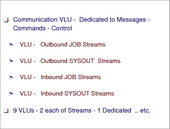
Virtual logical unit (VLU): In BDT, data and program logic that represents one user of a SNA session. The virtual logical unit enables more than one user to concurrently use a session.
A single set of VLUs between node A and B would consist of:
•Communication VLU (for control information)
•VLU for job stream 1 from node A to node B
•VLU for output stream 1 from node A to node B
•VLU for job stream 1 from node B to node A
•VLU for output stream 1 from node B to node A
A VLU can transfer data in two directions--either to or from a node. During the time a VLU is allocated to a specific transfer, however, that VLU can transfer data in only one direction. Once that transfer completes and BDT deallocates the VLU, the VLU will again be able to transfer data in either direction.
14.42 SNA NJE commands
SNA NJE commands
You can submit commands by typing them at your console, following the rules of command syntax.
Frequently used commands can be assigned to the program function keys (PF keys) on the console's keyboard. The PF keys can be set up to issue a command immediately when you press them, or to produce skeletal commands with blank spaces for you to fill in.
BDT command prefix
The prefix tells the system that the command is a BDT command. The prefix you use depends on the type of console you are using (MCS, JES3, or TSO):
•From MCS consoles:
– bdt-char - The IEFSSNxx parmlib member BDT subsystem definition keyword parameter C=bdt-char defines the BDT command character
•From JES3:
– *S,BDT, bdt_command
14.43 JES3 networking over TCP/IP

JES3 networking with TCP/IP
Starting with z/OS V1R8, JES3 provides support for NJE over TCP/IP. JES2 has been providing NJE over TCP/IP support since z/OS V1R7. VM (RSCS), VSE, and AS/400 have been providing NJE over TCP/IP support for several releases.
TCP/IP/NJE sessions take advantage of TCP/IP hardware independent layered stack to establish connections over a number of existing hardware protocols such as Ethernet and token ring. To use TCP/IP sessions, z/OS Communications Server TCP/IP requires z/OS UNIX System Services and ACF/VTAM to be configured and active. TCP/IP/NJE sessions support IPv6 and TLS/SSL, assuming that there is support on the node being connected to.
In JES3, TCP/IP/NJE can be thought of as a hybrid between BSC and SNA. NJE over TCP/IP uses the same record structure and data streams as BSC NJE. But like SNA NJE, in JES3, the NJE communication is driven through a separate Netserv address space that is analogous, although not functionally identical, to BDT.
Netserv address space
The role of the Netserv address space is to make all the communication interface calls to TCP/IP. The Netserv and JES cooperate to despool from JES data that is to be sent and to spool to JES data that is received. The Netserv functionality is in the JES Common component; therefore, with limited operational differences, it is the same in both JES2 and JES3.
IPv6
IPv6 uses a 128-bit address space, which has no practical limit on global addressability and provides 3.4 ¶ 10(50) unique addresses. This gives enough addresses so that every person could have a single IPv6 network with many nodes, and still the address space would be almost completely unused.
IPv4 addresses are represented in dotted-decimal format. The 32-bit address is divided along 8-bit boundaries. Each set of 8 bits is converted to its decimal equivalent and separated by periods. In contrast, IPv6 addresses are 128 bits divided along 16-bit boundaries. Each 16-bit block is converted to a 4-digit hexadecimal number and separated by colons. The resulting representation is called colon-hexadecimal.
The following are the three conventional forms for representing IPv6 addresses as text strings:
•The preferred form is x:x:x:x:x:x:x:x, where the x's are the hexadecimal values of the eight 16-bit pieces of the address. For example:
2001:DB8:7654:3210:FEDC:BA98:7654:3210
2001:DB8:0:0:8:800:200C:417A
It is not necessary to write the leading zeros in an individual field, but there must be at least one numeral in every field (except for the case described in the following bullet).
SSL and TLS
The Secure Socket Layer (SSL) protocol provides data encryption, data origin authentication, and message integrity. It also provides server and client authentication using X.509 certificates. SSL begins with a handshake during which the server is authenticated to the client using X.509 certificates. Also, the client can optionally be authenticated to the server. During the handshake, security session parameters, such as cryptographic algorithms, are negotiated and session keys are created. After the handshake, the data is protected during transmission with data origin authentication and optional encryption using the session keys.
SSL is not defined by the IETF. TLS is based on SSL and is defined by the IETF as RFC 2246.
The transport layer security (TLS) provides endpoint authentication and communications privacy over the Internet using cryptography. Typically, only the server is authenticated (i.e., its identity is ensured) while the client remains unauthenticated; this means that the end user (whether an individual or an application, such as a Web browser) can be sure with whom they are communicating. The next level of security in which both ends of the "conversation" are sure with whom they are communicating is known as mutual authentication. Mutual authentication requires public key infrastructure (PKI) deployment to clients unless TLS-PSK or TLS-SRP are used, which provide strong mutual authentication without needing to deploy a PKI.
TCP/IP/NJE performance enhancements
The TCP/IP network job receiver does not use double spooling like BDT does, the data is written to spool using USAM on the server side. When the job reaches the global, which builds the required job structures for the incoming job. The ownership of the spooled data is changed, but the job is not respooled.
14.44 Networking over TCP/IP

Networking over TCP/IP
Before data can be sent from one network job entry (NJE) node to another using TCP/IP, a virtual circuit must be established between the two nodes. A virtual circuit is a path between two applications over which TCP packets can be sent.
TCP sets up a connection between two endpoints (nodes), identified by the respective IP addresses and a port number on each. A port is the abstraction used by Internet transport protocols to distinguish among multiple simultaneous connections to a single destination host.
Each system in a network is assigned an IP address. Each TCP/IP service machine will have an IP address. Many applications on a system can use the TCP/IP service machine.
To enable the TCP/IP service machine to separate incoming packets, the applications use port numbers to indicate which packets correspond to which applications. TCP allows an application to open a virtual circuit in either passive mode (waiting for incoming requests to open, also known as server mode) or active mode (sending requests to open, also known as client mode). In general, one TCP application (the server) issues a passive open for a port number (known as the well known port) and the other TCP application (the client) will normally issue an active open for the well known port on the system (IP address) where the first (server) application is located. Either side can attempt to connect to the other side's port. The TCP connection or virtual circuit path between the two applications will be completed and data can be exchanged over the path.
14.45 Address spaces for JES3 TCP/IP/NJE

Address spaces for TCP/IP/NJE
In order to minimize the amount of duplicate implementation work in JES2 and JES3, all data communication in TCP/IP is done using a server address space, Netserv, which is one an additional part of the JES common component. JES code running in the Netserv server address space is required to control the definition and startup of the server. The JES code, invoked as exits in the server address space, moves data back and forth between the server and JES.
Netserv address space
The role of the Netserv address space is to make all the communication interface calls to TCP/IP on behalf of the JES. The Netserv listens for connections, incoming and outgoing data and cooperates with JES3 to read data from the spool or write data to the spool.
In the JES3 TCP/IP/NJE implementation, the Netserv address space can run either on the global or a local main processor. There is no limit to the number of Netserv address spaces that can run in the JES3 complex simultaneously.
A Netserv address space is a started task that requires authority to communicate with JES in order to spool, despool jobs and data sets. The common TCP/IP/NJE component, IAZNJTCP, uses TCP/IP services and, thus, must operate in the z/OS UNIX System Services environment. Therefore, the Netserv must have the proper authority to function. The required authorities consists of:
•A definition in the STARTED class to associate the started task with a userid.
•An OMVS segment in the security definition for the userid associated with the started task.
14.46 Defining JES3 TCP/IP/NJE

Defining JES3 TCP/IP/NJE
Any TCP/IP definitions to be used by JES3 must be defined in TCP/IP. This includes IP addresses, host names for the TCP/IP resolver, port names, and special service names. A JES3 node can use NJE protocol over TCP/IP to exchange jobs and data sets with a remote node. TCP/IP/NJE consists of the following TCP/IP definitions:
Netserv definition
A network server, typically abbreviated Netserv, which runs as a separate address space from JES3 on the global or any local that is at a sufficient software level. A NETSERV definition consists of the following information:
•A host name and port of a local socket over which the Netserv listen for incoming information from TCP/IP. The host name can be left unspecified in order to indicate to TCP/IP that it can use any IP address that is defined for the home node.
The port can be any number from 1 to 65,535. It can also be specified as, or allowed to default to, the special value of 0. This value indicates that a default service name should be used. The service name is VMNET for non-secure connections, and NJENET-SSL for secure connections, if TLS=YES is specified.
More than one Netserv can use the default IP address by omitting the HOSTNAME parameter, but they must specify unique ports.
•A system name where the Netserv is to run. If you do not specify a system name, the Netserv will run on the current JES3 global. If a DSI is performed while a Netserv is active, the Netserv will remain active on the same system on which it was active before the DSI. However, if the Netserv is subsequently brought down and back up, it will start on the new global.
•The name of the TCP/IP stack (i.e the name of TCP/IP address space) which contains the IP addresses over which the Netserv listens for incoming information.
|
Note: The Internet protocol suite (commonly TCP/IP) is the set of communications protocols that implement the protocol stack on which most networks run.
A protocol stack (sometimes communications stack) is a particular software implementation of a networking protocol suite. The terms are often used interchangeably. Strictly speaking, the suite is the definition of the protocols, and the stack is the software implementation of them.
|
Socket definition
A socket definition, defining a foreign socket that will be used to connect to TCP/IP. Each socket runs as a subtask under a Netserv address space. The SOCKET definition consists of the following information:
•A unique name representing the view of the socket by JES3 global, and used in inquiry and modify commands as well as internal JES3 processing of outbound and inbound TCP/IP data.
•A host name.
•A port number, handled the same way as the Netserv port number.
•The Netserv under which the socket task will run.
The concept of foreign and local sockets exist in TCP/IP. A JES3 socket defines JES3's usage of a foreign socket only. The local socket is implicitly defined by the NETSERV statement.
|
Note: A socket is an abstraction that represents an endpoint of communication. Most applications that consciously use TCP and UDP do so by creating a socket of the appropriate type and then performing a series of operations on that socket. The operations that can be performed on a socket include control operations (such as associating a port number with the socket, initiating or accepting a connection on the socket, or destroying the socket) data transfer operations (such as writing data through the socket to some other application, or reading data from some other application through the socket) and status operations (such as finding the IP address associated with the socket).
|
JES3 network node definition (NJERMT)
The NJERMT initialization statement to define a node in the JES3 job entry network. TYPE=TCPIP specifies the TCP/IP networking protocol to be used for communicating with a directly-connected remote node.
You may use the SECSIGNON parameter (valid for TYPE=TCPIP only) to indicate that the signon procedure includes additional checking using the encryption of a random string to confirm the identity of the node.
14.47 JES3 TCP/IP/NJE compared with BSC and SNA
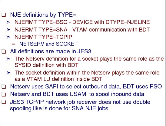
TCP/IP networking
The Netserv address space plays the same role in the TCP/IP/NJE function as BDT does in SNA. Certain definitions in one world have analogous definitions in the other. More specifically, the Netserv definition plays the same role as the SYSID definition in the SNA world, it defines the server address space. The socket definition within the Netserv plays the same role as a VTAM LU definition inside BDT. But a major difference is that while BDT has its own initialization stream and definitions, the Netserv and Socket definitions and modify commands to add, change, or delete these definitions all live in JES3.
Netserv and SAPI
The Netserv is similar to BDT in another way, too. When an outbound job stream is to be sent, both address spaces use a SYSOUT retrieval subsystem interfaces to despool this data from JES3 and then send it to the destination node. BDT uses the Process Sysout (PSO) SSI and USAM to despool data, the Netserv uses the Sysout Application Programming Interface (SAPI) and the block spooler.
SNA NJE with BDT
When a SNA NJE node gets an incoming network job, BDT receives the incoming network job (job header, data set header, data, and job trailer). It writes each of these to separate files on spool using DYNALLOC, OPEN, PUT, and CLOSE. This is the first stage of spooling. Then the NJERDR FCT, under control of module NJE Reader Driver (IATNTNR), reads the data off spool and feeds the resulting buffers to Networking Job/SYSOUT Receive module (IATNTJS), which builds the job structure and rewrites the data. This is the second stage of spooling. BDT's copy of the data and the job under construction both exist until the job structure is completely built at which point the BDT copy is purged.
Netserv and TCP/IP
The Netserv, like z/OS BDT, receives jobs or sysout streams from remote nodes and writes the data to the JES3 spool. To accomplish this, a modified SNA NJE like processing is used. When the Netserv server receives inbound network job records (these could include, either data or a job header, data set header, or job trailer) it calls, as an exit, a JES3 TCP (TCP/NJE) Address Space Exit Routine (in IATNTTXR module). IATNTTXR's functional routine allocates and opens a dummy spool data sets with external writer name TCPNJE for the job header, data set header, data, and job trailer.
Open and close processing for SYSOUT is data involves IATSIOR and IATDMJA and the communication data area JDS Interface Block (JIB). A JIB represents a single Job Data Set Control Block (JDS) that is being created in a user address space and is being sent over to the global to "register" as a global control block.
To avoid double spooling, TCP/IP/NJE requires multiple JDSes to have spool space allocated from the same Job/Data set Track Allocation Table (DSTAT), instead of individual DSTATs. Instead of individual JIBs, a Multiple JDS Interface Block (MJIB) is used by the JDS access SSISERV request. The MJIB consists of multiple JDS entries.
When Netserv has received each piece of the inbound network job’s data, JDS entries have been constructed, and placed into the MJIB, the MJIB is sent (SSISERV) to the global. If there are too many JDS entries to fit into one staging area, a multi-segmented staging area is sent.
JES3 global processing
On the global processor, IATDMJA, the JDS Access Interface module, invokes IATDMJA is IATDMJAM to process the multiple JDS interface block created in the Netserv address space. IATDMJAM converts the MJIB into the multiple JDS entries under a single TAT and prepare the incoming data for Networking Job/SYSOUT Receive Module (IATNTJS). IATNTJS creates a "utility" job to process the received data. The ownership of the JDS entry is converted from the Netserv job server to the “utility” job.
When an inbound network job is received, the NJERDR DSP acts as the front end to the networking receiver routine (IATNTJS) for SNA NJE processing (the NJE DSP driver (IATNTDR) is the front end for BSC/NJE processing).
JES3 output processing with TCP/IP
JES3 output service queues outgoing TCP NJE data on a special TCP queue. This results in a post of the TCP (TCP/NJE) DSP Driver (IATNTTDR) which builds a TCP NJE transaction and sends the it to the Netserv server. If Netserv is running on local, a JSERV is used to communicate the TCP NJE transaction to the local. On the global or the local, the TCP (TCP/NJE) Server Request module (IATNTTSR) is called to places the TCP NJE transaction on a Netserv's request queue and the communication task, IATNTTCT, in the Netserv address space is posted.
IATNTTCT's functional routine initiates a SAPI request to retrieve outgoing data for the job. To make the spool access faster, instead of using SAPI GET to retrieve the data, IATNTTCT then uses the block spooler (IATDMBS) to read the data.
14.48 JES3/TCP/IP/NJE transmission summary

Transmission summary
This figure is a summary of the process of sending a TCP/IP/NJE job from an originating node to execute on the execution node and the SYSOUT coming back to the originating node to print.
14.49 Defining TCP/IP/NJE NETSERV

Defining TCP/IP/NJE NETSERV
The NETSERV initialization statement describes the NETSERV address space. Its characteristics are the address space name, the TCP/IP stack it uses, the system where it runs, and various tracing information.
The *F NETSERV,ADD= operator command can dynamically add a new TCP/IP/NJE network server.
Netserv initialization statement parameters
Parameters on NETSERV initialization statement or command:
NAME= Specifies a 1-8 character name that uniquely identifies this Netserv and is also used to start the Netserv address space. The name must contain only A-Z, @, $, #, or 0-9 and cannot start with a digit.
HOSTNAME= Specifies the IP host name or IP address that the Netserv uses to listen over TCP/IP for incoming data. This name can be omitted to use the default, which tells TCP/IP to listen over any IP address that is defined for this processor. Multiple Netserv address spaces can listen over the same host name or use the default, if different ports are used.
The host name can consist of up to 60 characters and must be a legal TCP/IP address or host name defined to the TCP/IP resolver. The host name can |be in IPV4 or IPV6 format.
PORT= Specifies a port number that the Netserv will use, in combination with the host name, to listen over TCP/IP for incoming data. The port must be a number from 0 to 65,535. Port 0 indicates that when the Netserv starts a standard service name of VMNET. VMNET will be used instead of a numeric port. The service of VMNET corresponds to port 175. Although there is a corresponding port for the service NJENET-SSL, it is suggested that you use the TLS=YES parameter on the NJERMT statement or a *F NJE command instead.
SYSTEM= Specifies the name of the system that the Netserv will run on. If the SYSTEM= parameter is omitted, the Netserv will run on the global. After a DSI, an active Netserv that defaulted to the global will remain running on the old global. However, the Netserv will run on the new global if it is subsequently brought down and back up.
STACK= Specifies the name of the stack that TCP/IP uses to get its definitions. If the STACK= parameter is omitted, TCP/IP will use its default stack. The stack must contain only A-Z, @, $, #, or 0-9 and cannot start with a digit except when removing an existing assignment.
ITRACE= Indicates that internal tracing in the Netserv address space will be active.
JTRACE= Indicates that JES tracing will be active. JES tracing occurs during JES specific exit points in the Netserv when data records, headers, and trailers are transmitted and received.
14.50 Netserv address space

Netserv address space
The role of the Netserv address space is to make all the communication interface calls to TCP/IP. Netserv and JES3 cooperate to despool from JES3 data that is to be sent and to spool to JES data that is received. The Netserv functionality is in the JES common component (IAZNJTCP); therefore, with limited operational differences, it is the same in both JES2 and JES3.
The NETSERV address space can run either on the global or a local. There is no limit to the number of NETSERV address spaces that can run in the JES3 complex at a single time. You specify the system on which a NETSERV is to run when you define it to JES3.
Starting a TCP/IP/NJE network server *X TCP
Use the *X TCP command to start a network server address space (Netserv) for TCP/IP/NJE.
You must use the *X TCP command to start a Netserv before you can start communication to a node through any sockets that are defined under that Netserv. Following any restart of JES3, other than a cold start, if the Netserv was not canceled before the restart, it is automatically called again. Syntax:
*X TCP,NETSERV=ntsvname
The Netserv address space is started by using the ASCRE macro. (This is a common JES implementation.) The purpose for this, rather than a START command for a procedure, is so that a Netserv can work with no PROCLIB needed to be customized, although a RACF started task table is still needed.
When the *X,TCP,NETSERV=netserv command is issued, the TCP/IP DSP driver IATNTTDR gets control. A TCP DSP is attached and placed on the FCT chain. IATNTTDR calls TCP (TCP/NJE) Address Space Create (IATNTTAC) which will either handle the start on the global, if that is where the server is to run, or else JSERV a staging area to the correct system. The TCP (TCP/NJE) Address Space Initialization module (IATNTTAS) gets control in the newly created address space and performs all initialization activities before giving control to the common program, IAZNJTCP.
JES3 job name for the Netserv address space is IEESYSAS, MVS address space name for the Netserv is ntsvname.
z/OS Communications Server
The TCP/IP/NJE implementation supports virtual IP addresses (VIPA addresses), and the use of sysplex distributor to share IP addresses throughout a sysplex. There is no additional JES3 setup to take advantage of either of these features other than to specify the appropriate IP address or host name on the SOCKET initialization statement.
TLS/SSL support
Use of SSL and TLS by NJE/TCP is through Application Transparent TLS (AT-TLS). All of the SSL/TLS definitions are defined in the TCP/IP and security profiles, rather than in JES3 parameter statements. The TLS= parameter on the NJERMT initialization statement indicates whether the Transport Layer Secure facility will be used by any socket that is used to communicate with this node.
Netserv security product STARTED class definition
The NETSERV address space must be defined to the security product STARTED class. To minimize the number of STARTED profiles, it is suggested that you define all of your NETSERVs with a common name pattern so that you can cover them all with one generic profile.
RDEFINE STARTED JES3*.* STDATA( USER(JES3ID) GROUP(SYS1) TRUSTED(YES))
Security product user profile OMVS segment
The Netserv address space common component uses TCP/IP services and requires the z/OS UNIX System Services environment to operate. An OMVS segment in the security definition for the user ID associated with the started task.
ALTUSER JES3ID OMVS(UID(0) HOME(’/’) PROGRAM(’/’))
14.51 NJERMT statement (node)

NJERMT statement
The NJERMT statement has some new parameters that define a TCP/IP connection. The TYPE=TCPIP parameter defines the protocol as TCP/IP. The JOBTRANS, OUTTRANS, JOBRECV, and OUTRECV define the number of transmitters and receivers. Each of these can be from 1 to 7. According to the NJE protocol, the sum of the transmitters can be a maximum of 8, and likewise for the sum of receivers.
The TYPE=TCPIP parameter defines the node as an NJE over TCP/IP node. Following parameters on the NJERMT statement define:
•JOBTRANS, OUTTRANS, JOBRECV, and OUTRECV define the number of transmitters and receivers for the node. Each of these is a number between 1 to 7. According to the NJE protocol, the sum of the transmitters can be a maximum of 8, and likewise for the sum of receivers.
•SECSIGNON=YES defines that nodes signing on to each other verify their identity using session keys defined to the security product’s APPCLU class. JES3 allows the SECSIGNON=YES only for TYPE=TCPIP nodes.
•TLS=YES indicates that the TCP/IP Transport Layer Secure (TLS) facility will be used to encrypt transmissions.
*F NJE command
The *F NJE command can dynamically add a directly-connected node, delete a node or alias, change the type of networking protocol you are using between your node and a remote node, and change the usage of secure signon protocol and the Transport Layer Secure facility.
14.52 Define TCP/IP SOCKET

SOCKET initialization statement
A socket defines the IP address or host name of a TCP/IP/NJE remote node, and a port. In order for two nodes to communicate using the TCP/IP protocol, a socket must be started on one node. This node is referred to as a client. The corresponding node at the other end of communication is referred to as a server. If JES3 is a server node, a server socket will be defined automatically. If JES3 is a client node, a socket must be define using the SOCKET initialization statement or JES3 commands.
NAME= Name is a 1-8 character name that uniquely identifies this socket. The name must contain only A-Z, @, $, #, or 0-9 and cannot start with a digit.
HOSTNAME= The hostname specifies the IP host name or IP address that this socket will use to communicate with TCP/IP.
The host name can consist of up to 60 characters and must be a legal TCP/IP address or host name defined to the TCP/IP resolver. The host name can be in IPV4 or IPV6 format.
PORT= Specifies a port number that the socket will use, in combination with the host name, to communicate with TCP/IP. The port must be a number from 0 to 65,535. A port of 0 indicates that when the socket starts a standard service name of VMNET, VMNET will be used instead of a numeric port. The service of VMNET corresponds to port 175. Although there is a corresponding port for the service NJENET-SSL, it is recommended that you use the TLS=YES parameter on the NJERMT statement or *F NJE command instead.
NETSERV= Specifies the name of the Netserv on which the socket will be activated. This parameter does not need to be specified during initialization, but if the parameter is omitted, it must be modified later. Otherwise, the socket cannot be started.
NODE= Specifies the name of the node that will use this socket. This parameter does not need to be specified during initialization, but if the parameter is omitted, it must be modified later. Otherwise, the socket cannot be started.
ITRACE= Indicates that internal tracing in the socket address space will be active.
JTRACE= Indicates that JES3 tracing will be active. JES3 tracing occurs during JES3 specific exit points at the socket level in the Netserv address space during which data records, headers, and trailers are transmitted and received.
VTRACE= Indicates that verbose tracing will be active at the socket level. Verbose tracing involves various diagnostic messages being written to the console and job log from the Netserv address space.
*F SOCKET,ADD operator command
The *F SOCKET,ADD= command to dynamically adds a new TCP/IP/NJE socket connection that is used to communicate with a remote NJE node using the TCP/IP protocol.
*S TCP,SOCKET=sockname operator command
The *S TCP,SOCKET= command starts a socket under a Netserv, in order to begin communication with a remote node with TCP/IP protocol.
14.53 *X TCP - How It's Done

*X TCP - how it's done
The visual shows JES3 processing steps and modules for the *X TCP command.
*S TCP SOCKET - how it's done
Processing steps by the load modules:
•IATCNIN - Validate *S TCP SOCKET= command
•TCP/IP NJE DSP console appendix (in IATNTTDT Data CSECT) - Save the START command text and post the TCP FCT ECF for 'START' and 'CANCEL' commands.
•IATNTTDR - Validate *S TCP SOCKET= request, call TCP (TCP/NJE) Server Request (IATNTTSR) to queue the start socket request and post the communication task (IATNTTCT) in the Netserv address space.
•IATNTTCT - Receives the requests for the Netserv sent by the global. IATNTTCT determines which function is needed in order to send the request on to IAZNJTCP and calls TCP Server/Socket Services (IATNTTSS).
•IATNTTSS - Posts the appropriate IAZNJTCP work ECB to tell IAZNJTCP there is incoming work.
14.54 TCP/IP/NJE example environment

JES3 node definitions
The visual shows a scenario where two nodes, one in WTSCPLX9 and one inWTSCPLC4, wish to communicate using NJE over TCP/IP. Each node defines itself as HOME=YES and the remote node as TYPE=TCPIP. Each node also defines a NETSERV address space. Note that both nodes do not specify the SYSTEM parameter on the NETSERV statement, this defaults to the global processor. The WTSCPLX9 node also defines a SOCKET for the WTSCPLX4 remote node, and a port.
The HOSTNAME and PORT parameters on the NETSERV statement are optional. The default is that the NETSERV listens to TCP/IP over any host and port that it can for the node. The HOSTNAME and PORT parameters shown illustrates the relationship between the NETSERV definition on one node and the SOCKET definition on the other.
DSI and Netserv address space
There is an optional parameter, SYSTEM, on the NETSERV definition that is not shown here. It defines which system the NETSERV address space is to be active. The default is the JES3 global. If a DSI is done, the default moves to the new global, but only when the Netserv is inactive. If a Netserv defined to default to the global is active while a DSI is done, it will remain up where it is, but if it is brought down and back up, it will come up on the new global.
14.55 Example - on WTSCPLX9 start TCP/IP/NJE

Example - on WTSCPLX9 start TCP/IP/NJE
You must use the *X TCP command to start a Netserv address space before you can start communication to a node through any sockets that are defined under that Netserv. Following any restart of JES3, other than a cold start, if the Netserv was not canceled before the restart, it is automatically called again.
The sockets that are defined for the requested node need to be started by an internally generated *S TCP,SOCKET= command.
|
*I NETSERV=netserv
*X,TCP,NETSERV=netserv
|
Displaying a TCP/IP/NJE Network Server
information.
Starts the NETSERV address space. All the sockets under this NETSERV are also activated.
|
|
*S,TCP,NODE=nodename
*S,TCP,SOCKET=socket
|
Starts communication with all sockets assigned to the specified node.
Starts communication with the specified socket.
|
|
Note: JES3 converts internally *S,TCP,NODE=nodename to *S,TCP,SOCKET=sockname commands. The sockname is the name of the socket that will used for this node.
|
14.56 Example - on WTSCPLX9 convert networking protocol

Convert networking protocol
It is possible to convert nodes from one networking protocol to the other. In other words, nodes that are currently using BSC, SNA, or TCP/IP protocol can be converted to one of the others. The following scenarios describe converting an existing SNA node to TCP/IP.
Before converting to TCP/IP, you must:
•Define a Netserv using the NETSERV statement or the *F,NETSERV,ADD command.
•Define profiles for the Netserv in the STARTED security class.
•Define a socket describing the IP address or host name of the remote node, and a port.
•Define any IP addresses and host names that nodes use to TCP/IP.
•You can dynamically add nodes; restarting JES3 is necessary only to make the additions permanent when the nodes are defined in the JES3 initialization stream.
Before you can establish any TCP/IP network connections, z/OS Communications Server TCP/IP must be active, which in turn requires z/OS UNIX System Services and ACF/VTAM to be active. A TCP DSP can be started by issuing *CALL,TCP. This can start a Netserv address space. If the TCP DSP is started by issuing *CALL,TCP before TCP/IP is active, the Netserv address space waits until TCP/IP is active. If the remote node is JES2 or JES3, you must start the appropriate Netserv there as well. The sockets can then be activated from either side. The operator can migrate any jobs that remain waiting for BDT to despool the output by using the NJEROUT DSP. Jobs are transmitted when the socket is activated.
The visual shows the messages issued during the conversion of an existing SNA node to TCP/IP.
14.57 Example - on WTSCPLX9 reroute network jobs
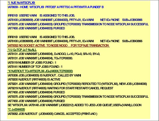
Example - On WTSCPLX9 reroute network jobs
The NJE reroute DSP (NJEROUT) reroutes a network job to a remote location or back to its original destination. You can also reroute the output to a different VM userid or RJP workstation. The NJEROUT DSP is valid for rerouting work to both TCP/IP/NJE, BSC/NJE and SNA/NJE nodes.
Rerouting NJE work
The NJEROUT DSP allows you to reroute:
•A job that was sent to your node from a remote node
•A job that was submitted locally
•SYSOUT streams that are being routed through your node
•SYSOUT streams (from JES3 jobs run at your node) that were originally destined for a remote node
Job and SYSOUT streams, however, cannot be rerouted from the home node using this facility.
Job and SYSOUT streams
The networking protocol that a node is using does not affect the rerouting of job or SYSOUT streams. Job or SYSOUT streams that are currently destined to a node that uses one networking protocol of BSC, SNA or TCP/IP can be rerouted to another node using the same protocol or a node using a different protocol. Rerouting is especially useful if you are converting from one protocol to the other, because some jobs might have been queued for one resource or the other during the conversion period.
To begin the rerouting process, the operator must *X the NJEROUT DSP. The *S and *R commands can then be used to reroute specific jobs.
Message in the visual
The visual shows the messages issued for job transmission to execution node and a rerouting operation:
•JES3 message IAT9352 informs of a failed NJE transmission
•*I U Q=TCP J=? N=ALL output service command with the appropriate parameters displays information about TCP/IP/NJE network jobs. TCP/IP/NJE network jobs might be either network job streams or network SYSOUT streams.
•Message IAT8131 identifies jobs found in output service Q=TCP
•The *X NJEROUT TO=node JG=(jes3_job_nbr,tcp_group_nbr) command requests the specified job’s TCP output data to be rerouted
JCL for the example job
The following JCL was used to create the messages shown in the visual.
|
//VAINIXMT JOB (999,POK),EXPERT,MSGLEVEL=1,MSGCLASS=A,
// NOTIFY=VAINI,REGION=0M
//XMIT XMIT DEST=NOGO,DLM=$$
//VAINIEX JOB (999,POK),EXPERT,MSGLEVEL=1,MSGCLASS=A,
// NOTIFY=WTSCPLX9.VAINI,REGION=0M
//OPUT OUTPUT JESDS=ALL,DEST=WTSCPLX9
//TMPROC PROC
//TMP EXEC PGM=IKJEFT01,DYNAMNBR=99
//SYSTSPRT DD SYSOUT=*,DEST=(WTSCPLX9,VAINI)
// PEND
//EXEC EXEC TMPROC
//SYSTSIN DD *
LISTC LEVEL(VAINI)
$$
|
14.58 Example - WTSCPLX4 messages

Example - WTSCPLX4 messages
The visual shows the messages issued on node WTSCPLX4 during the execution of the example operations.
When WTSCPLX9 connects to WTSCPLX4, a “server” socket @0000001 is created. The *I,SOCKET=@0000001 display shows that the socket is assigned to node WTSCPLX9.
When a job was submitted on WTSCPLX4 to execute on WTSCPLX9, the following messages were issued on WTSCPLX4:
IRR010I USERID VAINI IS ASSIGNED TO THIS JOB.
IAT6100 (JOB19166) JOB VAINITS (JOB22217), PRTY=01, ID=VAINI NET-ID=*NONE SUB=JOB22069
IAT9370 JOB VAINITS (JOB22217) GROUPID (TCP00000) TRANSMISSION TO NODE WTSCPLX9 SUCCESSFUL
SE 'WTSCPLX9: IAT9140 JOB VAINITS (JOB44011) ADDED TO JES3 JOB QUEUE',USER=(VAINI),LOGON
IAT7450 JOB VAINITS (JOB22217) PURGED
SE 'WTSCPLX9: IAT6108 JOB VAINIEX (JOB...ID) ENDED, MAXCC=0000 ',USER=(VAINI),LOGON
IAT9127 JOB (JOB22217) IS VAINITS FROM WTSCPLX4(VAINI )
SE 'WTSCPLX4: IAT9141 JOB VAINITS (JOB22217) ADDED TO JES3 OUTPUT QUEUE',USER=(VAINI),LOGON
14.59 Summary of JES3 TCP/IP/NJE commands

Examples of JES3 NJE commands
Use the *I SOCKET= command to display information about a socket or all sockets.
The *I NETSERV=ALL displays information about all Netserv address spaces. Up to 999 address spaces may be defined.
The existing *I NJE command can be used to display TCP/IP/NJE nodes.
14.60 Secure signon
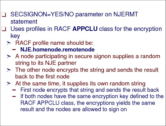
Secure signon
With TCP/IP, there is a greater potential for a hacker to pretend to be an NJE over TCP/IP node than with BSC or SNA nodes. It is much harder for someone to hack into BSC or SNA and pretend to be an NJE node. Generally, this can happen if hardware equipment is connected the wrong way. To cope with this potential risk, JES3 provides a mechanisms to secure the NJE over TCP/IP communications. These are secure signon and the transport layer secure (TLS) protocol.
Secure signon involves an encryption key, which is on a node by node basis (and only directly connected nodes). The encryption key is stored in the RACF APPCLU class as a profile which the JES code can extract.
NJERMT statement
Secure signon is selected by using the SECSIGNON=YES/NO parameter on the NJERMT statement.
The RACF profile name should be NJE.homenode.remotenode. A node participating in secure signon supplies a random string to its NJE partner. The other node encrypts the string and sends the result back to the first node. At the same time, it supplies its own random string.
The first node must then encrypt that string and send the result back. If both nodes have the same encryption key defined to the RACF APPCLU class, the encryptions will yield the same result and the nodes are allowed to sign on. Otherwise the signon fails. This is a means for two nodes to authenticate one another.
14.61 Secure signon

Secure signon
Secure signon is an optional security mechanism to ensure that two nodes prove their identities to each other during NJE signon. Secure signon is provided only in JES2 and JES3.
Secure signon has nothing to do with Transport Layer Secure (TLS) in TCP/IP. TLS is a separate security feature.
Secure signon uses the APPCLU security class to provide an encryption key. A node participating in secure signon supplies a random string to its NJE partner. The other node encrypts the string and sends the result back to the first node. At the same time, it supplies its own random string. The first node must then encrypt that string and send the result back.
If both nodes have the same encryption key defined to the APPCLU class, the encryptions will yield the same result and the nodes are allowed to sign on. Otherwise the secure signon fails.
|
Note: The APPCLU security class must be active on both nodes.
The SESSION parameter in the APPCLU security class on both nodes must specify a session key and both session keys must be the same. The name of the APPCLU security profile is NJE.homenode.rmtnode.
|
14.62 Coexistence considerations
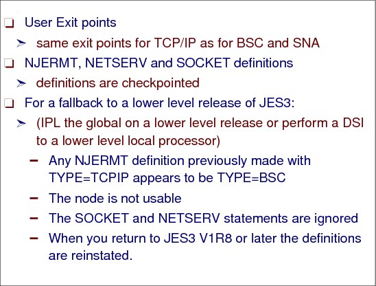
User exits
JES3 job networking user exits:
•IATUX35 (Validity Check Network Commands)
•IATUX36 (Collect Accounting Information)
•IATUX37 (Modify the JES3 Networking Data Set Header for Local Execution)
•IATUX37 - Changed installation exit for TCP/IP.
•IATUX38 (Change the SYSOUT Class and Destination for Networking Data Sets)
•IATUX39 (Modify the Data Set Header for a SYSOUT Data Set)
•IATUX40 (Modify Job Header for a Network Stream Containing a Job)
•IATUX42 (TSO Interactive Data Transmission Facility Screening and Notification)
•IATUX43 (Modify Job Header for a Network Stream Containing SYSOUT Data)
•IATUX50 (JES3/BDT Unknown BSID Modifier Exit)
•IATUX58 (Modify Security Information Before JES3 Security Processing)
•IATUX59 (Modify Security Information After JES3 Security Processing)
•IATUX66 (Determine Transmission Priority for a SNA/NJE Stream)
•IATUX67 (Determine Action When Remote Data Set Is Rejected by RACF)
•IATUX68 (Modify Local NJE Job Trailers)
Coexistence considerations
The IATXNTS macro is used to search the networking node table to verify the validity of a destination. Since JES3 z/OS V1R8 adds a new TCP/IP type of node, a new keyword is required for IATXNTS to support TYPE=TCPIP nodes. The new keyword is TYPETCP. If you have a user modification or installation exit that calls IATXNTS and uses the TYPEBSC and the TYPESNA keywords, you must also specify the TYPETCP keyword. The three keywords must all be specified or all omitted.
This change must be made before starting JES3 level HJS7730. The change is required even if you do not plan to make use of NJE over TCP/IP support. If you do not have any intention of using the NJE over TCP/IP support yet, or if you do not know what TCP/IP action to take for a node, you can specify the same label on TYPETCP as you do for TYPESNA.
Falling back to a previous release
When you use the new NJERMT, NETSERV and SOCKET definitions on JES3 level HJS7730, the new definitions are saved on the spool. After falling back to a lower level release of JES3 (IPL the global on a lower level release or perform a DSI to a lower level local processor), any NJERMT definition previously made with TYPE=TCPIP appears to be TYPE=BSC. The node is not usable. The SOCKET and NETSERV statements are ignored. When you return to JES3 release HJS7730, the definitions are reinstated.
14.63 Coexistence messages

Coexistence messages
During fallback to a lower release, the following messages will be issued:
IAT4131 SPOOL RECORD ERROR DETECTED (JCT) FOR JOB TCP (JOBxxxxx)
IAT4174 CONFIRM DELETION OF JOB TCP (JOBxxxxx) DUE TO SPOOL RECORD ERROR(S) (CONTINUE, SNAP(,ALL) OR TERMINATE)
When returning to a JES3 level HJS7730, the following messages will be issued:
IAT4159 ERROR RESTORING TCP/IP CHECKPOINT
IAT4103 ERROR(S) ENCOUNTERED RECOVERING JES3 STATUS CHECKPOINT DATA (CONTINUE OR CANCEL)
When you enter the *X DSI command on the global, if any NETSERV address spaces are active, the following message will be issued:
IAT0921 DSI - WARNING: SYSTEM sysname HAS nnnnn ACTIVE NETSERVS
..................Content has been hidden....................
You can't read the all page of ebook, please click here login for view all page.