

JES3 dynamic support programs
JES3 is composed of routines called dynamic support programs, (DSPs). With the same mechanisms it uses for processing jobs, JES3 schedules and processes DSPs. JES3 users can write their own dynamic support programs to customize JES3 processing in their system.
Most of the JES3 programs in the global processor is divided into parts called dynamic support programs, or DSPs. There are DSPs for reading job input, for processing jobs, and for writing job output. What distinguishes DSPs from ordinary routines or subroutines is that DSPs are schedulable units. Before a DSP is executed, it must be scheduled by JES3. (DSPs have priorities that govern their position in a JES3 dispatching queue.)
System programmers can alter what DSPs do (with installation exit routines), or they can write new DSPs to supplement or replace the DSPs shipped with JES3.
15.1 Scheduling and DSP dictionary
Scheduling DSPs
Each small piece of work that JES3 performs when processing a job is accomplished with a JES3 program called a dynamic support program, or DSP. Each DSP is represented on the FCT chain by one or more FCT entries or elements. The elements on the FCT chain are executed according to their priority, and are placed on the FCT chain with the high priority element first. The higher priority elements are executed before the lower priority elements.
DSP dictionary entry
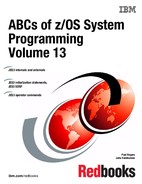
The IATYDSD macro generates an entry for a dynamic support program (DSP) in the DSP dictionary, (module IATGRPT), or in a C/I FSS address space, (module IATGRPTF). An entry in the table is required for each DSP in order for it to be recognized as part of JES3. The following are parameters on the macro that define the DSP characteristics:
ISDRVR Specifies the 1- to 8-character name of the DSP whose entry is being created by this macro. If the DSP is to be callable, this name will appear as the argument of an *X,dspname command. If the DSP is to be processable, this name will appear in the //*PROCESS dspname JCL statements. The label is required.
PRTY Specifies the priority to be assigned to the DSP, in the range from 1 through 255. This priority becomes the FCT priority when the DSP is activated.
REENT Specifies that the DSP is reenterable.
DRVR Specifies the name of the DSP driver module to be loaded, if necessary, for each use of the DSP.
CSECT Specifies the name of the data CSECT to be loaded by the job segment scheduler driver (module IATGRJR) for each use of the DSP.
MAXCT Specifies the maximum number of copies of this DSP that may be concurrently active. The number must be within the range 1 through 65535. If this parameter is not specified for a DSP specifying REENT=YES, no MAXCT limit is imposed. This parameter is dynamically alterable by using the *MODIFY command unless you specify MUCC=NO.
JSS scheduling
JSS schedules all DSPs into execution. The function of the job segment scheduler (JSS) is to select scheduler elements (SEs) and prepare them for processing by JES3. Every SE denotes a unit of work JES3 must perform to process the job. Those units of work re processed sequentially. Each SE in the job control table (JCT) represents one or more dynamic support programs (DSPs), and each DSP is represented by one function control table (FCT) entry on the FCT chain, the master JES3 dispatching queue.
15.2 Writing DSPs
Creating DSPs
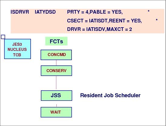
Before your DSP can be executed (after you've assembled it and link-edited it), you need to include the name of the DSP in the DSP dictionary. To do so, add one or more of each of the following two macros in module IATGRPT:
•IATYDSD - Generates one entry for the DSP in the DSP dictionary.
•IATYFCD - Generates an entry in the permanent function control table (FCT). You need one IATYFCD macro for each FCT entry you want.
|
Note: If you want the DSP to have a resident FCT, include the IATYFCD macro in IATGRPT, but do not include IATYDSD.
|
Update of DSP dictionary
If you are updating the DSP dictionary, add the new names to the end of the dictionary and perform a warm start or a hot start. If you add new DSP names to some position other than the end of the DSP dictionary, you must cold start the JES3 system because the DSP numbers reside in control blocks in spool data sets. All routines should reference JES3 control blocks using named fields in JES3 DSECTs. Routines should not make references using an absolute displacement because the displacements of fields are subject to change.
All JES3 tables should be referred to by using DSECTs generated by mapping macros. For ease of reference, place these macros at the beginning of a program after the prolog but before any executable instructions. Use of the mapping macros insulates the user-written DSPs from changes to system control blocks.
15.3 Steps for scheduling DSPs
DSP processing after scheduling
The following represents the recommended standard sequence of required tasks for the initialization phase of a user-written DSP, which the job segment scheduler (JSS) will schedule. Use the list only as a general guide since, at times, you can omit steps or vary the sequence to reflect particular processing requirements.
As a minimum, perform step 1. The other steps depend on whether the DSP needs a job description accounting block (JDAB) and job data set (JDS) information.
1. Establish a base register for the DSP. By convention, DSPs use register 10 as the standard base register. Although another register can be used, using the standard base register convention will ease program analysis.
2. Issue the LOGIN macro to establish the means by which the operator can communicate with the DSP.
3. Establish the JESTAE environment.
4. Issue the IATXCNS macro specifying TYPE=GET. On return, register 1 contains the address of the parameter buffer for the job.
5. Extract the parameter information from the parameter buffer in the previous step.
6. Issue the IATXCNS macro specifying TYPE=RELEASE to free the parameter buffer.
7. Issue the GETUNIT macro to request any required JES3 support devices. If the required devices are unavailable, cancel or request specialized rescheduling for the unavailable devices. The system programmer must specify the type of devices required by the DSP in the device requirements table (DRT). The DRT is located within the DSP dictionary and is built using the REQ parameter on the IATYDSD macro. The system programmer must fill in the GETUNIT LIST (GLIST) before the DSP issues the GETUNIT macro.
8. Issue the JDSGET macro to get the JDS, and extract FDBs for the data sets to be processed as input, if any. The JDS contains an FDB and data set name for each SYSOUT data set or data set entered through the input stream (SYSIN) that is associated with the job.
9. Issue the JDSREL macro to release the JDS.
10. I Issue a sign-on message. Once the DSP has verified its parameters and has successfully obtained its devices, it can issue a sign-on message to notify the operator that the DSP is active.
Register conventions
Register usage for installation exits is defined for each exit in In general, registers 11, 12, 14, and 15 on entry are as defined below but other input registers are also provided. Also, most installation exits use the same register conventions.
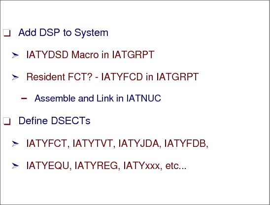
JES3 stores the following data in the registers before passing control to a DSP:
•Registers 0 through 10 are undefined.
•Register 11 contains the address of the function control table (FCT) for the DSP.
•Register 12 contains the address of the JES3 transfer vector table (TVT).
•Register 13 is the base register of the DSP's data CSECT, if one is defined for the DSP.
•Register 14 is the address to which a called routine must return.
•Register 15 is the entry point address of the called program.
Once JSS schedules the DSP and it gets control, the DSP should initialize, do some housekeeping, and finally have a termination routine.
15.4 Writing a user DSP

Creating a user DSP
When writing a user DSP, define it in the IATGRPT module and to make it callable by the operator, specify XABLE=YES, XABLE=YES specifies that the DSP can be called by using the *X command.
CONCMD DSP
The *X command issued by the operator is read by a DSP named CONCMD, which is responsible for command processing. The CONCMD DSP is represented by a resident FCT entry, so it will be dispatched (if there work to do) when the multifunction monitor reaches the entry.
WTDDRVR DSP
The CONCMD DSP simply routes the *X command to another DSP, the work-to-do driver (WTDDRVR). Like the CONCMD DSP, the WTDDRVR DSP is represented by a resident entry on the FCT chain. It is the WTDDRVR DSP which actually begins the process of adding the called job to the system.
15.5 DSP initialization
Steps during DSP initialization
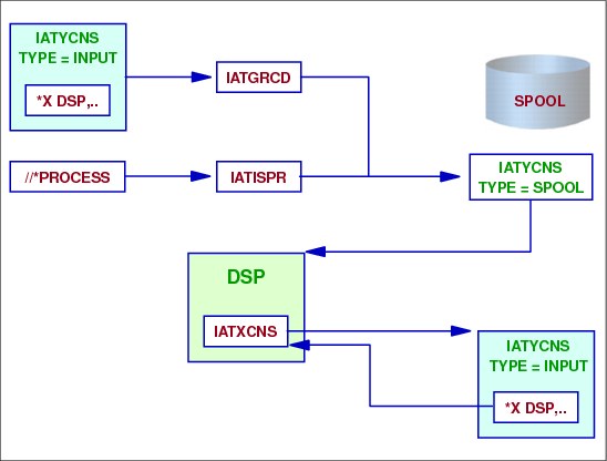
The IATYCNS macro generates various tables used to communicate information between console service and other functions within JES3. It is a mapping macro.
Retrieve operator call of DSP
The IATXCNS TYPE=INPUT macro reads a console input buffer record (field CONSMESS of data area IATYCNS) from the JES3 spool. The macro can either:
•Read the job description accounting block (JDAB) associated with the called job, and read and return the address of the console input buffer record, or
•Release the console input buffer record returned by a previous macro call as shown in the last step.
DSP created using //*PROCESS statement
A console spool message buffer is created for the DSP. For the called DSP, module IATGRCD creates the spool message buffer containing the DSP related information.
DSP gets scheduled
When the DSP is scheduled by JSS, the called or PROCESSed DSP information is obtained by the DSP from the spool message buffer. Now the DSP knows what the call parameters are.
15.6 DSP initialization processing
DSP processing
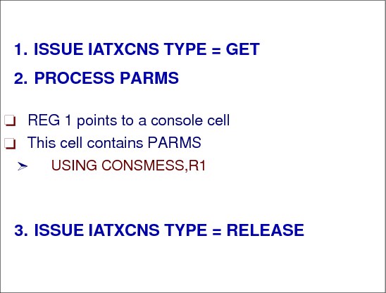
Issue the IATXCNS macro specifying TYPE=GET. On return, register 1 contains the address of the parameter buffer for the job. You now have access to the operator *X command and its parameters.
When finished processing the *X command parameters, issue the IATXCNS TYPE=RELEASE to free the JDAB parameter buffer that contained the parameters. When doing this RELEASE, you must specify that the console input buffer record returned by the previous IATXCNS TYPE=GET macro call is to be released. The address of the console input buffer record address must be specified by the BUFFER= parameter when issuing the macro.You can use register 2.
CONSMESS data area
The IATXCNS macro reads a console input buffer record (field CONSMESS of data area IATYCNS) from the JES3 spool. The macro can either:
•Read the job description accounting block (JDAB) associated with the job, and read and return the address of the console input buffer record, or
•Release the console input buffer record returned by a previous macro call.
|
Note: The console input buffer is sometimes called an input message buffer or an input parameter buffer. Issuing the IATYCNS macro with TYPE=INPUT generates the buffer table, as shown in the previous visual.
|
15.7 DSP housekeeping
DSP functions during start-up
DSPs, except DSPs running in a C/I FSS address space, must issue a LOGIN macro for operator communication and must always respond to console messages. DSPs running in a C/I FSS address space must issue a LOGIN macro to define the entry point to a console appendage routine but do not communicate directly with the operator.
MVS macro usage
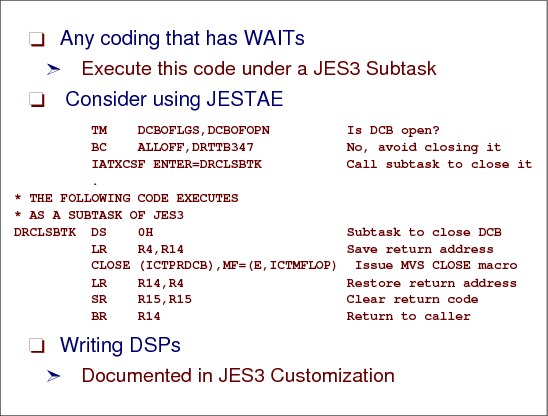
Do not use MVS macros that either implicitly or explicitly use the MVS WAIT function, except under the control of a JES3 subtask (see the IATXCSF macro). These macros include:
|
ATTACH FIND PURGE
BLDL LINK WAIT CLOSE LOAD WTO DOM LOCATE WTOR DYNALLOC OPEN XCTL |
DSPs should not use these macros. Use of these macros disrupts the flow of processing on the global main and can cause a degradation in system performance by possibly causing JES3 itself to wait. The queued access methods, QSAM and QISAM, use these macros and, therefore, should not be invoked. If your program needs to use one of the above macros, you must first establish a JES3 subtask environment in which to use the macro. To do so, include the IATXCSF macro in your program. IATXCSF passes control to a JES3 subtask.
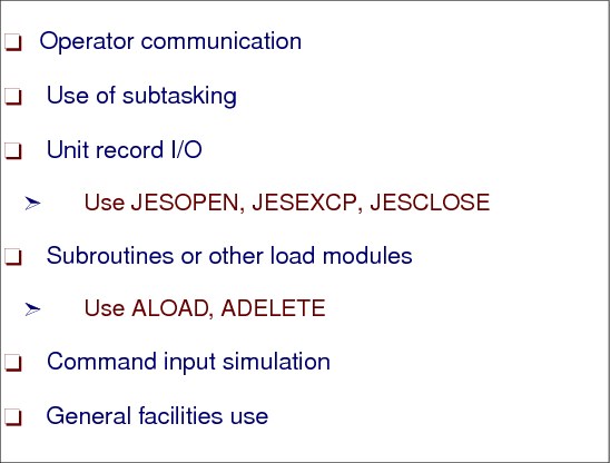
Unit record I/O
DSPs must perform all unit record and tape I/O using the JESOPEN, JESEXCP, and JESCLOSE macros. DSPs and installation exit routines operating in a C/I FSS address space cannot perform unit record and tape I/O.
Loading modules
If your program consists of more than one module, you should organize it so that the first module is reenterable and all other parts are at least serially reusable. If you use multiple modules in your program, use the ALOAD and ADELETE macros for dynamic loading and unloading of the subprograms. In case of a failure in your DSP, be sure to set up a JESTAE environment that includes the ADELETE macro.
Console communication
All DSP-to-operator communication is accomplished by the console service routines. Each DSP that requires two-way communication with the operator must define a console appendage routine for accepting asynchronous entries from console service. The DSP must use the LOGIN macro to define the console appendage routine's entry point. For reentrant DSPs, therefore, appendages are typically located in the DSP data CSECT. See next visual.
General facilities use
The IATXCSF macro provides the ability to execute code containing implicit or explicit MVS WAIT macros (for example: OPEN, CLOSE, FIND). This is done by passing control from one of the JES3 subtasks provided for this purpose to an appendage routine specified by the ENTER parameter.
The two types of JES3 subtasks that can be invoked by the IATXCSF macro are:
General subtasks Any caller can use these subtasks.
Specific subtasks Callers specifying the subtask ID can use these subtasks.
IATXCSF uses one of the four general subtasks when the ID parameter is not specified. The caller receives control under one of the subtasks and has no control over which subtask is used. When running under a general subtask's control, you must free (before relinquishing control) all resources that were acquired while running under control of the subtask.
15.8 Operator communication with DSPs

LOGIN macro
DSPs, except DSPs running in a C/I FSS address space, must issue a LOGIN macro for operator communication and must always respond to console messages. DSPs running in a C/I FSS address space must issue a LOGIN macro to define the entry point to a console appendage routine but do not communicate directly with the operator. Instead, the CIDRVR FCT receives the operator commands and routes them to the C/I FSS address space using the MVS functional subsystem intercommunication (FSI).
Console appendage
All DSP-to-operator communication is accomplished by the console service routines. Each DSP that requires two-way communication with the operator must define a console appendage routine for accepting asynchronous entries from console service. The DSP must use the LOGIN macro to define the console appendage routine's entry point. For reentrant DSPs, therefore, appendages are typically located in the DSP data CSECT.
The console appendage is entered when a *START, *RESTART, or *CANCEL command is received for the DSP, and may be entered when a *FAIL command is received.
Because DSP console appendages run under the CONCMD FCT, which is the highest priority FCT, their processing time should be as short as possible. You should limit processing to deciding whether to accept the command, and, if necessary, saving the command and posting the command processing routine of the DSP.
15.9 DSP initialization and messages

Operator communication with DSP
The LOGIN macro establishes communication and transfer of data between console service and the dynamic support program (DSP) using the macro. This macro must be executed by each DSP that allows the receipt of messages and responses from the consoles.
The return codes, shown in the visual, specify what to reply is sent back to the operator or that the command is queued to be processed by the DSP.
Then set your ECF to allow new messages from the operator and issue an AWAIT waiting for the next communication from the operator.
|
NI DJDFLAG2,FF - DJNOMSG - DJNOSTRT allow messages
AWAIT ECFMASK = X'40',ECFADD = DJDFLAG2
|
Command from operator
On entry to the console appendage, register 1 contains the address of the console message buffer (which is mapped by the TYPE=INPUT expansion of the IATYCNS macro). The buffer includes the console destination block (CNDB), verb code, message length, and flags used by the JES3 command processing routines. Register 0 contains the FCT address of the function that owns the console appendage. Once your DSP processes the operator command, the DSP issues a message to let the operator know everything is okay.
15.10 Use of subtasking
Use of subtasking
As stated in a previous figure, use the IATXCSF macro to obtain a subtask to execute code that would cause a WAIT of the JES3 task. The macro specifies the address of the code to execute under the subtask (MYSUB).
JESTAE macro
If your DSP uses an MVS function that could cause an abnormal termination, be sure that you set up a JESTAE recovery environment. The purpose of the recovery environment is to insure that a failing DSP does not also bring down the JES3 primary task (IATNUC).
The JESTAE macro defines a DSP abnormal exit routine. The JESTAE exit routine must be resident throughout the life of the JESTAE request. A DSP can issue more than one JESTAE macro. All JESTAE requests issued by programs running under the same FCT are queued so that the exit established by the most recent JESTAE request will be the first to get control. If this exit fails or requests that the abnormal termination continue, the exit established by the previous JESTAE request will get control. This process is called JESTAE percolation.
Coding example
The coding example in the visual illustrates the use of the IATXCSF macro. The code to be executed under control of the subtask begins at label DRCLSBTK.
See z/OS JES3 Customization, SA22-7542document for more information.
15.11 Dump job DSP

Dump job DSP
Dump job is a specialized JES3 utility designed to dump jobs from the JES3 job queue to tape, and later, reintroduce those jobs back into the job queue at the point of processing at which they had been dumped.
This facility is used when a system requires a software change, when a test is to be conducted on a dedicated system, when the user shuts down the complex but requires the integrity of the job queue to be maintained or when job data is being archived. Use dump job for:
•Archive. Some installations regularly dump jobs to tape to save them for a given period of time.
•Provide additional spool space. Jobs can be dumped to tape when the current workload is heavy, and restored when the workload lessens.
•Perform preventive maintenance. Jobs not complete at a time when preventive maintenance is scheduled can be dumped and subsequently restored.
•Migrate. Installations can save and restore jobs when migrating from one level of JES3 to another.
15.12 Dump job DSP - (spool offload)

Calling dump job
When calling dump job to dump to tape, specify OUT= to some tape device. As many as eight DJ DSPs can be invoked concurrently, permitting you to dump and restore jobs simultaneously.
You can specify the range of jobs to be selected for dumping or restoring. Jobs can be in any non active stage of processing and, with the exception of DJC networks and jobs waiting to be transmitted across networking lines, do not need to be in hold status.
The selection criteria allows dumping by:
•Job number - J=12
•Priority - P=2
•DJC network name N=PAYR
•All jobs in the queue
•By job class
•All jobs that are not part of a DJC network
•All DJC networks
•All jobs within a specific range of job numbers that are not part of a DJC network
15.13 Dump job reset option

Dump Job reset option
Dump job looks at every job once as it makes a pass through the job queue. Jobs are flagged as being looked at to avoid dumping the same job twice.
When a DJ DSP is invoked to dump a job or net, the DJ facility sets dump control flags for each job processed. Because of these flags, any jobs remaining on the JES3 job queue after DJ has processed them cannot be dumped again until the flags are reset.
Use the *START command with the RESET parameter to reset DJ dump control flags for all jobs or a selected set of jobs on the JES3 job queue. Enter this command when all other dumping using the DJ facility is complete.
15.14 Dump job server mode
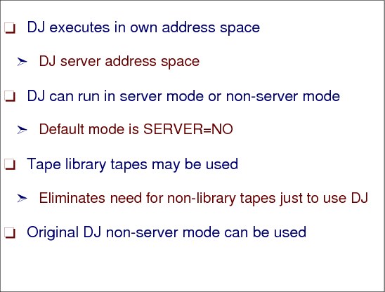
Dump job server mode
Dump job can be run in either server or non server mode. When dump job is run in server mode, a dump job server address space is started to allocate the tape device. All tape-related functions such as reading or writing to the tape are done from the dump job server address space.
You can use the dump job facility to dump jobs to tape devices that you have defined through the use of the JUNIT and XUNIT initialization parameters or to the tape devices that include the IBM 3494 and 3495 Tape Library Dataserver.
Using JUNIT and XUNIT to perform the dump job process is the traditional way that maintains that JES3 manages the tape I/O to JES3 defined tape devices. Using the IBM 3494 and 3495 Tape Library Dataserver as well as any tape devices in the JES3 system to perform a dump job exploit a new feature of dump job. This feature is running dump job in server mode In this mode, the tape I/O portion of dump job runs in its own address space. The major MVS I/O facilities are used freeing the installation from having to remember the volumes and their current order when the job restore is performed.
15.15 DJ server mode
Using server mode
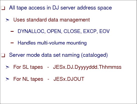
In the server address space, all tape handling is done by standard data management macros, which includes the handling of multi-volume tape dumps.
The data set name that is generated is different for standard label tapes versus unlabeled tapes.
•For standard label tapes, the data set name has the following format, where jesn is the JES3 subsystem name.
jesn.DJ.Dyyyyddd.Thhmmss
•For unlabeled tapes, the data set name is not unique and has the following format, where jesn is the JES3 subsystem name.
jesn.DJOUT
To dump jobs to tape, issue the *S DJ command and specify which jobs you want dumped.
15.16 DJ server mode tape drives
Defining JES3 tape drives
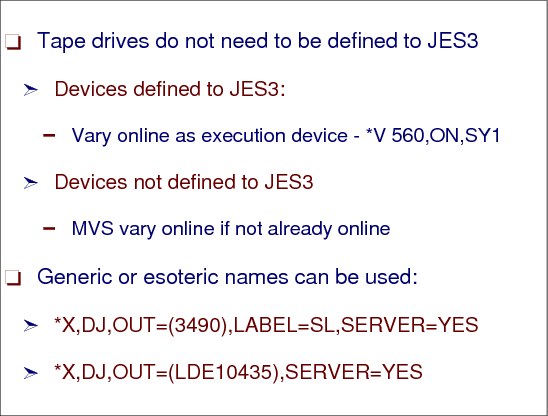
The device used by Dump Job when using server mode does not have to be defined to JES3, but you may do so. Also, a generic device name (e.g. 3490) or an esoteric device name (e.g. TAPE) may be specified on the *X command.
If you have tape DEVICE statements in your initialization stream for use only by Dump Job, these statements can be removed once you decide only to run Dump Job in server mode. To remove tape DEVICE and SETNAME statements from the initialization stream requires a JES3 warm start.
If you want JES3 to continue to manage tape devices for jobs in execution but no longer need them for Dump Job, you can remove the DTYPE, JNAME, and JUNIT parameters from the tape DEVICE statements and perform a hot start with refresh. If you change your mind and want to add them back, this can also be accomplished by performing a hot start with refresh.
Using tape drives
The following is an example of dumping jobs to tape when dump job is in server mode. The first thing that needs to be done is to *X the dump job DSP. In this case, we are creating a standard labeled tape on device 560. If device 560 is defined as a JES3 managed device, it must be varied online as an execution device to the global processor (SY1):
*V,560,ON,SY1
IAT8180 0560 VARIED ONLINE TO JES3 ON SY1
*X,DJ,OUT=560,LABEL=SL,SERVER=YES
IAT8180 0560 VARIED ONLINE TO JES3 ON SY1
*X,DJ,OUT=560,LABEL=SL,SERVER=YES
Instead of using a specific device, a generic or esoteric device name could have been specified on the *X command. In this case, the device name must be enclosed in parentheses:
*X,DJ,OUT=(3490),LABEL=SL,SERVER=YES
or
*X,DJ,OUT=(LDE10435),SERVER=YES
or
*X,DJ,OUT=(LDE10435),SERVER=YES
|
Note: When using non-server mode, the device used by Dump Job must be defined to JES3 via a DEVICE statement and must be defined as a shared device. It must be defined as a JES3 global device via the DTYPE, JNAME, and JUNIT parameters, and as an execution device via the XTYPE and XUNIT parameters.
|
15.17 Using DJ server mode

Using serve mode to dump jobs
The following is an example of restoring jobs from tape when dump job is in server mode. When calling the dump job DSP, for standard label, server mode requests, the DSN= parameter must specify the name of the data set that was created when the jobs were dumped to tape:
*X,DJ,IN=560,SERVER=YES,DSN=JES3.DJ.D1998091.T163039
As a result of the *X command, a dump job server address space is started. The dump job server address space initializes and allocates the tape device. The tape device is allocated with deferred mounting so you will not see any IAT5210 messages asking the operator to mount the tape if this is a JES3 managed device. A mount message (IEC501A) will be issued when a *S DJ command is issued and the tape data set is opened.
If a unlabeled tape was created when the jobs were dumped to tape, the VOL= parameter must be specified in addition to the DSN= parameter. This is necessary because unlabeled tapes are always created and cataloged with the data set name jesn.DJOUT. If you create multiple unlabeled tapes, JES3 needs to know the volsers to determine which instance of jesn.DJOUT you want to restore. This is not a problem for standard labeled tapes because the data set name that is generated and cataloged is unique.
*X,DJ,IN=560,SERVER=YES,DSN=JES3.DJOUT,VOL=(TAPVOL,TAPVL2,TAPVL3)
15.18 DJ server mode examples

Server mode example
As a result of the *X command, a dump job server address space is started. The dump job server address space initializes and allocates the tape device. The tape device is allocated with deferred mounting so you will not see any IAT5210 messages asking the operator to mount the tape this is a JES3 managed device. A mount message (IEC501A) will be issued when a *S DJ command is issued and the tape data set is opened. The following messages are seen by the operator:
|
IAT6306 JOB (JOB00033) IS DJ , CALLED BY 01
IAT6100 ( DEMSEL ) JOB IEESYSAS (JOB00034), PRTY=15, ID=*UNKNOWN SY1 IEESYSAS IEF403I IEESYSAS - STARTED - TIME=16.11.04 IAT5110 JOB IEESYSAS (JOB00034) GET 255 T SCRTCH ,SL JES3.DJ.D1998091. |
Server address space
The job name of the dump job server address space is DJ followed by the job number of the DJ DSP that started the server address space. To display information about the dump job server address space, issue one of the following commands:
D A,DJ* or D A,DJ000033
15.19 DJ server mode command examples

Command examples to display active server job
The job name of the dump job server address space is DJ followed by the job number of the DJ DSP that started the server address space.
The job name of the dump job server address space is DJ followed by the job number of the DJ DSP that started the server address space. To display information about the dump job server address space, issue one of the following commands:
D A,DJ* or D A,DJ000033
*I J=34
15.20 DJ operator messages
Operator messages
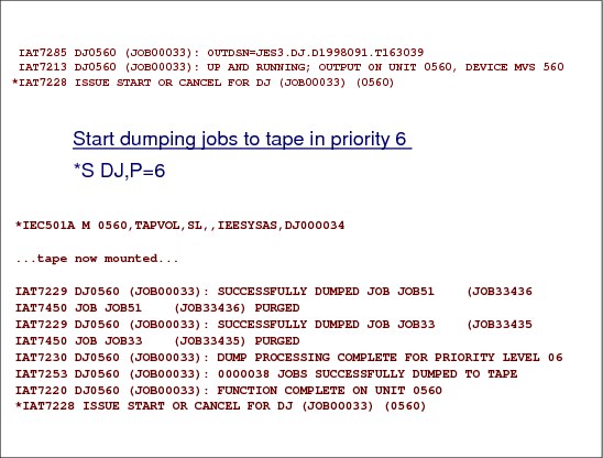
After the dump job server address space has successfully initialized, dump job issues the messages below to show that it is ready to begin dumping jobs to tape. Message IAT7285 contains the name of the tape data set that contains the jobs that are dumped to tape. This data set name must be specified on the *X DJ command when you restore the jobs from tape.
IAT7285 DJ0560 (JOB00033): OUTDSN=JES3.DJ.D1998091.T163039
IAT7213 DJ0560 (JOB00033): UP AND RUNNING; OUTPUT ON UNIT 0560, DEVICE MVS 560
*IAT7228 ISSUE START OR CANCEL FOR DJ (JOB00033) (0560)
IAT7213 DJ0560 (JOB00033): UP AND RUNNING; OUTPUT ON UNIT 0560, DEVICE MVS 560
*IAT7228 ISSUE START OR CANCEL FOR DJ (JOB00033) (0560)
To dump jobs to tape, issue the *S DJ command and specify which jobs you want dumped. In the example that follows, jobs in priority 6 will be dumped to tape:
*S,DJ,P=4
As a result of the *S command, dump job dumps the requested jobs to tape:
*IEC501A M 0560,TAPVOL,SL,,IEESYSAS,DJ000034
Eventually, the following will be seen:
tape now mounted
15.21 DJ server mode commands

Server mode commands
You can now issue additional *S DJ commands to dump other jobs to tape. When you are finished dumping jobs to tape, you can cancel the DJ DSP. As a result, the dump job server address space will close the tape data set and end, as follows:
*C,DJ
IEF234E R 0560,TAPVOL,PVT,IEESYSAS,DJ000034
IEF471E FOLLOWING VOLUMES NO LONGER NEEDED BY IEESYSAS
TAPVOL.
IEF404I IEESYSAS - ENDED - TIME=16.37.00
IAT7200 DJ0560 (JOB00033): DUMP JOB DSP TERMINATING
IAT7450 JOB DJ (JOB00033) PURGED
IEF234E R 0560,TAPVOL,PVT,IEESYSAS,DJ000034
IEF471E FOLLOWING VOLUMES NO LONGER NEEDED BY IEESYSAS
TAPVOL.
IEF404I IEESYSAS - ENDED - TIME=16.37.00
IAT7200 DJ0560 (JOB00033): DUMP JOB DSP TERMINATING
IAT7450 JOB DJ (JOB00033) PURGED
15.22 DJ log data set

DJ log data set
The visual shows the DJ log data set which contains the DJ messages related to what was dumped to the tape.
In addition to writing all messages to the calling console, the DJ facility logs in a separate data set all DJ START commands and all DJ job-related messages that indicate whether a job was successfully dumped or restored. If tracing is specified via the TRACE parameter on the *S command, all trace output is also recorded in the data set. You can print the DJ message log data set by specifying the SPIN=YES parameter on the *S DJ command. If SPIN=YES is not specified on the START command, the DJ message log data set is printed when the DJ DSP is cancelled.
When the first start command completes, a second command can be issued to dump a different set of jobs to the tape.
*S DJ,P=1
15.23 Restore jobs in server mode

Dump jobs in with server mode
If a unlabeled tape was created when the jobs were dumped to tape, the VOL= parameter must be specified in addition to the DSN= parameter. This is necessary because unlabeled tapes are always created and cataloged with the data set name jesn.DJOUT. If you create multiple unlabeled tapes, JES3 needs to know the volsers to determine which instance of jesn.DJOUT you want to restore. This is not a problem for standard labeled tapes because the data set name that is generated and cataloged is unique.
*X,DJ,IN=560,SERVER=YES,DSN=JES3.DJOUT,VOL=(TAPVOL,TAPVL2,TAPVL3)
As a result of the *CALL command, a dump job server address space is started. The dump job server address space initializes and allocates the tape device.
IAT6306 JOB (JOB33530) IS DJ , CALLED BY 01
IAT6100 ( DEMSEL ) JOB IEESYSAS (JOB33531), PRTY=15, ID=*UNKNOWN
IEF403I IEESYSAS - STARTED - TIME=16.51.54
IAT5110 JOB IEESYSAS (JOB33531) USES T TAPVOL ,SL JES3.DJ.D1998091
IAT6100 ( DEMSEL ) JOB IEESYSAS (JOB33531), PRTY=15, ID=*UNKNOWN
IEF403I IEESYSAS - STARTED - TIME=16.51.54
IAT5110 JOB IEESYSAS (JOB33531) USES T TAPVOL ,SL JES3.DJ.D1998091
After the dump job server address space has successfully initialized, dump job issues the following messages to show that it is ready to begin restoring jobs from tape.
IAT7213 DJ0560 (JOB33530): UP AND RUNNING; INPUT ON UNIT 0560, DEVIC
*IAT7228 ISSUE START OR CANCEL FOR DJ (JOB33530) (0560)
*IAT7228 ISSUE START OR CANCEL FOR DJ (JOB33530) (0560)
To restore dump jobs from tape, issue the *START,DJ command and specify which jobs you want dumped. In this example, we will restore jobs in priority 6:
*S,DJ,P=4
As a result of the *S command, dump job restores the requested jobs from the tape (message IAT7255 is displayed on two lines due to space limitations):
*IEC501A M 0560,TAPVOL,SL,,IEESYSAS,DJ033530
(tape now mounted)
IAT7255 DJ0560 (JOB33530): JOB JOB21 (JOB33414) ENTERED INTO PRIORITY
06 AS JOB (JOB33525)
06 AS JOB (JOB33525)
15.24 Creating JESNEWS data set

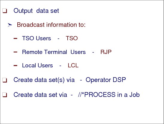
JESNEWS data set
JES3 provides a special utility program that allows you to broadcast information to local, TSO/E, and RJP users. This utility, dynamic support program (DSP), can be run at the same time as the other support functions of JES3, such as input service and the main device scheduler. You can start the DSP at an operator console by using the *X command.
You can use the JESNEWS DSP to create, to replace, or to delete three special output data sets that can be included as part of a normal output data set burst page. The JESNEWS DSP work on three types of data sets: local, TSO/E and RJP. Use these data sets to send information to JES3 users.
You can end processing of the JESNEWS DSP by entering the following command:
*C,JESNEWS
The text is entered by the operator using the *S JESNEWS command and when finished entering the text, the *R JESNEWS command activates the data set.
15.25 JESNEWS DSP
Using the JESNEWS DSP
You can use the JESNEWS DSP to create, to replace, or to delete three special output data sets that can be included as part of a normal output data set burst page. The JESNEWS data set is printed at the end of the output for 3 types of users:
•TSO users jobs
•RJP submitted jobs
•Local users jobs
JESNEWS with //*PROCESS statement
This nonstandard job uses one or more special processing functions in place of or in addition to standard processing or skips one or more of the standard functions. Specify a nonstandard job by following the JOB statement with a JES3 //*PROCESS statement for each processing function.
The JESNEWS data set is created by the operator command or by executing a job with //*PROCESS JESNEWS with the data following the //*PROCESS statement.
//JESNEWS JOB ..........
//*PROCESS JESNEWS
TYPE=ADD,DS=TSO
/*
15.26 Dump core DSP

Dump core (DC) DSP
The dump core DSP is used to display and modify data in main storage, to intercept program flow during execution, and to format control blocks for debugging. This facility can be used only on the global processor.
Use Dump Core (DC) to display storage allocated to JES3. Dump core commands allow you to:
•Display and then modify data in main storage
•Intercept program flow during processing
•Format control blocks for debugging purposes
•Find the location of a module in storage
•Display a requested portion of JES3's storage
•Set traps
•Display and print JES3 control blocks
Determine where the output from the dump core DSP should be routed. You specify the destination of the output by using the OUT= parameter on the *X DC command when you invoke the dump core facility or any *S DC command.
15.27 JCT dataspace problem determination

Using DC for JCT dataspace
The DC DSP displays a specific JCT entry or all JCT entries. The options to display the JCT entry are:
•JCT entry from Data Space
•JCT entry from spool
•Both the Data Space entry and the spool entry
The operator command is:
*S DC,OPTION=(SNP=JCT),J=jobno|ALL
The above option allows for display of a specific job using J=jobno or of all jobs using J=ALL.
To specify the location of the JCT, the SOURCE keyword can be used:
SOURCE=DSPACE|JCTDS|ALL
Where:
DSPACE Display Data Space copy of JCT
JCTDS Display JCT spool data set copy of JCT
JCTDS Display JCT spool data set copy of JCT and JCT Data Space copy.
JMF is changed to support JCT Access Method related information. Also displayed is the JQE table information.
The report name is JQE/JCT Access Method Report.
The three main areas of the report are:
•JCT Data Set Information
•JCT Data Space Information
•JQE Information
New IPCS models
Two new IPCS models for the JCT Data Space changes are included in this release. The two macros are IATYJCT and IATYJQX.
SYS1.DUMPxx
For errors encountered accessing the JCT Data Space, a dump of the JES3 address space and a dump of the JCT Data Space are taken.
15.28 JCT problem determination

JCT problem determination
The JCT dataspace can be dumped using the DUMP command. Specify the ASID of the dataspace and the owner JES3JCT when prompted for a reply to the DUMP command.
15.29 Job related information DSPs

DISPLAY DSP
Use the *X DISPLAY command to display detailed information about a single job or all jobs in the JES3 job queue. The *X DISPLAY command obtains the diagnostic information from the JES3 control blocks associated with the jobs in the job queue.
OUT=devname on the *X command returns output to the device type you specify. If you omit this parameter, the output goes to the calling console.
You can specify a job number or name to display or a priority level to display jobs.
DISPDJC DSP
Use the DISPDJC facility to display the status of a dependent job control network on a printer. For each network the DISPDJC facility displays:
•The name of the network.
•The FLAG1 parameters as defined in the job network control block (JNCB).
•The FLAG2 parameters as defined in the JNCB.
•The number of jobs in the designated network.
•The number of jobs in the designated network that have completed.
For each job in the network the DISPDJC facility displays:
•The job name
•The current status of the job (completed, active, inactive, or in network hold)
•The names of the jobs that are successors to the designated job and cannot be processed until its completion
•The name and net-id of a successor in another network
•The number of predecessor jobs that must complete before the designated job can be processed
•The action to be taken when a predecessor job ends normally or abnormally
..................Content has been hidden....................
You can't read the all page of ebook, please click here login for view all page.