Chapter 7
Essential Technologies for 5G-Ready Networks: DC Architecture and Edge Computing
As alluded to throughout the book thus far, data centers (DCs) play an important role in hosting critical applications and components that enable full-stack services for mobile subscribers. Historically, DCs have included packet core components, management functions, authentication, and authorization tools, as well as security apparatus such as firewalls. Until recently, network architectures were developed to administer these functions from a few central locations, dubbed the main DC or central DC. However, the evolving service requirements as well as the mobile core and radio access network (RAN) decomposition have led to distribution of these data centers throughout the network. In this distributed DC model, the transport becomes more intertwined with the DC infrastructure, and thus any transport network design must consider DC placement and integration. The technologies discussed in this chapter will cover DC architectural evolution as well as provide foundational knowledge for implementing and integrating DCs in a 5G-ready mobile communication network (MCN).
Data Center Basics
Modern-day DCs find their roots in mainframe or server rooms, where the equipment necessary for continued system operation would be located. In hindsight, earlier mobile telephone exchanges that housed the equipment and databases required to register mobile subscribers and process mobile calls could be considered a DC for mobile networks of that time. Oftentimes, data was not a primary resource in these locations but rather a peripheral asset used by the equipment placed there. As the networks and systems grew, these specialized locations sometimes spanned the whole floor or even multiple building floors. These locations also required special considerations such as rows of racks to mount various equipment, raised floors, ceiling-mounted cable runners, and ample cooling capabilities. While present in virtually every service provider network, it was not until the late 1990s and early 2000s when the need for storing enormous amounts of user data was realized by the large DCs as we know them today.
Rise of Large-Scale Data Centers
DCs are a mainstay of any service provider network, acting as a data and application repository. Originally starting off as locations to store giant mainframes, big computer systems, and relevant data storage devices such as tape drives, the data centers of today have gone beyond the confines of a single floor or a building and instead cover hundreds of thousands of square feet of land.1 A large-scale DC might house hundreds of thousands of devices, providing not only data storage but also computation power for applications, data processing, management, and analysis. Across all of its DC locations, a large service provider’s network may easily contain north of a million devices, and these numbers continue to grow.2
The growth in the size and relevance of DCs was driven by the introduction and mass adoption of the Internet. Collectively, these DCs have to store unfathomable amounts of World Wide Web data as well as provide services to billions of Internet subscribers around the globe. Digitizing of everyday tasks, such as Internet banking, e-commerce, and navigation, as well as over-the-top (OTT) services like music and video streaming, created a need for larger, more extensible data centers, which was further fueled by the growing mobile communications industry. In the early 2000s, prompted by the continual growth of DCs, the Telecommunications Industry Association (TIA), in collaboration with the American National Standards Institute (ANSI), published the ANSI/TIA-942 specification to identify guidelines for DC planning and classification. ANSI/TIA-942 defines four different tiers of DCs, starting from Tier 1, which is a simple, basic DC with no redundancy, all the way to Tier 4, which includes super-scaled large DCs with layers of built-in redundancy and high availability, including geo-redundancy. ANSI/TIA-942 also defines guidelines for physical layout, site space specifications, cabling infrastructure, rack sizes, physical entry/exit locations, as well as environmental consideration within the DC.3
The growing need for DCs also spurred different business models, such as on-premises (on-prem) DCs, co-location DCs or co-location racks, managed hosting services, and, more recently, public cloud. As the name suggests, an on-prem DC is located on the premises of, and wholly owned and operated by, the business entity requiring services from it. For larger DCs, this model may represent a steep upfront cost, deep DC technology expertise, as well as ongoing maintenance and upgrade expenses. The use of on-prem DCs for services offers the highest level of flexibility and customization, albeit at a higher cost compared to the other models. This is by far the most deployed model today and accounts for approximately 55% of all application workloads across all DC deployment models.4
Public cloud is the other end of the spectrum, where a cloud service provider offers general-purpose data center infrastructure for businesses to deploy their application workloads. Cloud-based DCs offer significantly lower startup costs, with the flexibility to scale up or scale down resource usage, as required. Although public clouds are geared toward generic applications meant to be run on commercially available servers, specialized applications requiring custom hardware (such as some Mobile Core and RAN components) are increasingly being rearchitected to make them “cloud friendly.” Today, public cloud–based DCs account for just under a quarter of all application workloads but are expected to grow significantly, mostly at the expense of on-prem DCs.
Co-location and managed hosting make up the rest of the data center deployment models. When using a co-location DC or co-location rack model, a company could rent the whole data center or a few racks from the co-location service provider. In this case, multiple companies may have DC equipment co-located in a single location, hence the name. Co-location allows smaller enterprises to reduce their real estate CAPEX by renting the required space instead of building their own DC. However, only the facility (location, power, peering points) is provided by the co-location provider, while the equipment, its installation, and maintenance remain the responsibility of the company planning to use the DC, resulting in higher startup costs when compared to a managed hosting or public cloud model.
In a managed hosting option, an enterprise customer rents not only the DC space but also the equipment, such as servers and storage. These servers are installed and maintained by the managed hosting provider but are dedicated to the customer whose applications are being hosted on them. In some cases, service providers use their own on-prem DCs to provide managed hosting services.5 In some ways, managed hosting is similar to public cloud, but it acts like an off-prem DC in the sense that the data center requirements are more customized than in a public cloud. This allows a lot more specialized applications to run in a managed hosting environment; however, the capability gap between the public cloud and managed hosting models is quickly narrowing. At the time of this writing, managed hosting and co-location collectively account for less than a quarter of all application workloads and are expected to lose market share to more flexible and cheaper public cloud–based options.6
Regardless of the size or deployment model used, the building blocks of an effective, efficient, and extensible DC have remained the same and are discussed in the next section.
Building Blocks of a Data Center Fabric
The term data center fabric is commonly used today to collectively refer to compute and storage equipment, as well as the transport network that efficiently interconnects them. The networking between these devices is expected to provide full connectivity with high bandwidth while minimizing the number of connections and maximizing availability in case of any link or network device failure. The simplest way to achieve such inter-device connectivity would be to use full-mesh connectivity, with every device talking to every other device. Such a mesh network, however, is challenging to implement due to the high number of interfaces needed. Also, it would not be efficient in maximizing link utilization and would potentially result in a large number of idle or under-utilized links.
Instead, large-scale DCs today use a design conceived many decades ago called the Clos architecture to implement their networks. The design is named after its inventor, Charles Clos, who published a design in 1953 comparing different hierarchical switching stages and their advantage over fully meshed connectivity.7 Even though this was initially proposed as a solution for telephone exchanges, the idea is very much applicable and used for designing networks in a modern DC. This simple idea describes a hierarchy (called stages) of switching devices, with the devices in the first or last stage representing the input or output into the Clos-based network, whereas the devices in each intermediate stage connect only to the devices in the next or preceding stage.
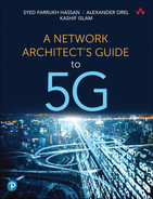
This DC architecture is also called a fat-tree design, because the number of subsequent stages typically has fewer switching devices, with a fatter yet lower number of downlinks. Consequently, the switching devices at the periphery of this network are commonly called leaf nodes, while the subsequent layers are commonly referred to as spine and super-spine nodes. As this design can be visualized through the analogy of threaded fabric being stretched, the resulting network of these spines and leaves is commonly referred to as a Clos fabric. Figure 7-1 illustrates how these spine and leaf nodes collectively form the fabric. As shown in the figure, the number of stages can vary depending on the data center requirements. Network architects can easily spot the similarities between this architecture and the traditional access-aggregation-core architecture that is commonly used in IP transport networks. Leaf nodes can be compared to the access routers, the spines are the equivalent of the aggregation layer, whereas super-spines are comparable to high-speed core routers.
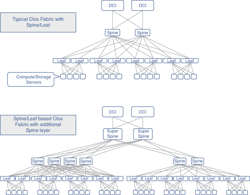
FIGURE 7-1 Overview of a Data Center Fabric
Spines are typically deployed in multiples of two for a collection of leaf nodes. Depending on the design choices, the spines may or may not have a link between them. The Clos fabric requires only as many uplinks from the leaf nodes as the number of spine nodes to which they are connecting, which due to the fat-tree design, is typically fewer than the number of leaf nodes. These connections are then used as equal-cost links with traffic load-balancing techniques used at higher layers. The path between any two leaf nodes can therefore use all of these equal-cost links, thus equally utilizing them for the inter-device traffic (also called east-west traffic in the DC world). The use of multiple spines, and corresponding spine-leaf links, automatically offers protection against link or device failures. The beauty of this design is not limited to its efficient network utilization and failure resilience, but can also be found in its simplicity and extensibility by replicating for scale. Additionally, Clos fabric provides predictable latency between all pairs of connected hosts, making it a highly suitable and reliable choice for the DC fabric.
Although the east-west traffic, which essentially is the traffic within the DC fabric, is expected to be the dominant traffic, the DC devices do need to communicate with the outside world as well. The devices or routers implementing this external connectivity are called Data Center Interconnect (DCI), and the traffic through them is colloquially referred to as north-south traffic. DCI is further discussed later in this chapter.
The DCs of today use the spine-leaf architecture irrespective of their physical scale and size. In a typical large DC, a pair of leaf nodes is connected to servers within each rack—thus giving rise to the term top of rack (ToR) devices for referring to the leaf nodes. Rows of these racks can be served by a pair of spine nodes. These spine nodes, in turn, can connect to the DCI for facilitating the outside world connectivity, as Figure 7-2 illustrates.
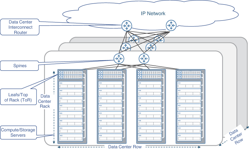
FIGURE 7-2 Typical Data Center Layout
Considerations for Space, Power, and Cooling
Typically, network architects focus on technical aspects of a design, such as feature capability, scalability, redundancy, extensibility, and so on, whereas nontechnical considerations like space, physical layout, power, and cooling often take a backseat and are left for the consideration of the deployment teams. Given the increase in the size of DCs and with the tens of thousands of devices deployed in each one of them, these considerations have moved to the forefront of deployment and operational concerns. From a business standpoint, while the DC must be able to fulfill all the service requirements, it must also perform these functions while minimizing the overall costs—both capital and operational.
Real estate availability at a reasonable cost is one of the key factors for any operator in deciding where to place its large DCs. Driven by the number of racks and devices required to fulfill service requirements, the provider must ensure ample physical space is available to house current and forecasted devices. Selecting a suitable facility, which can sometimes span hundreds of acres for large cloud DCs such as the ones built by Microsoft, Google, and Amazon, is the first step toward building a viable DC infrastructure. There might not always be vast open spaces, however, at least not in the desired location. In those cases, DCs use alternate approaches such as vertical expansion (across multiple floors in a building) instead of horizontal buildouts. This is especially true when DCs need to be placed in proximity to their users or essential utilities in densely populated cities such as New York, Tokyo, Hong Kong, and other similar places. In these cases, consideration of additional structural and cabling requirements across different floors comes into play. The placement of DCs in more urban locations becomes especially important with the growth in mobile services and multi-access edge computing, where mobile functions must be hosted closer to the end subscriber. Both the horizontally and vertically scaled DCs are an essential part of today’s networking infrastructure, which deliver services essential for running an end-to-end network.
Whether it is a large or small DC, power consumption is another key consideration when planning a data center. The total power requirements for any DC is a combination of the power consumed by equipment contained in the DC and the power required to maintain the cooling and other auxiliary systems to ensure a viable operating environment across the facility. Over the past several years, telecom and networking equipment manufacturers have focused on reducing power consumption by their devices while increasing features and functionality. In fact, environment friendly products using reduced power while providing equal or highest functionality are routinely featured as a value-added differentiation by major networking equipment providers.
Aside from the power required to run the devices in the DC, additional power is required to provide cooling in the facility itself. DC owners use a metric called Power Usage Effectiveness (PUE) to measure the effectiveness of power used in a given DC. PUE is defined as a ratio between the energy required to turn on all devices in the data center and the total power used in said data center. The goal is to use as much power as possible toward the IT equipment and lower the cooling system’s power consumption, thus providing a better PUE value. In order to achieve the best PUE and to lower the cooling and heating costs, DC owners are experimenting with new and innovative approaches. Some of these techniques include using reusable and geothermal power sources wherever feasible and even placing DC modules underwater.8 Placing technical equipment in a fully submersible environment presents its own set of challenges, but with the help of new, cutting-edge technology, innovators and early adopters are continually pushing the envelope to create more energy-efficient data centers. In addition to power consumption, the availability of uninterrupted power brings another aspect of considerations. Besides relying on multiple feeds from the power grid for redundancy, additional backup power sources such as generator and battery backup are also used in all DCs.
For optimal DC planning, more logistical considerations need to be taken into account, such as terrain, risk of natural disasters, temperate weather conditions, and so on. Even though these are important considerations, going into a detailed analysis of these factors digresses from the technical focus of this book. Entire books are dedicated to the cost modeling of DCs and could be used to learn more about the nontechnical aspects of a DC, such as site selection, layout planning, and buildout.9 This section aims to introduce network architects to the challenges of a DC site selection that otherwise might not be apparent when using a technical-only point of view. With the growing number of DCs in 5G networks, courtesy of packet core and RAN decomposition, site selection as well as heating and cooling of these DCs have become important operational considerations. At the same time, given the rise of cloud-based services, mobile service providers are increasingly opting to minimize the startup cost and are outsourcing the complexities of maintaining and managing DCs to cloud service providers wherever possible, as discussed in the next section.
From Centralized to Distributed to Cloud Data Centers
Like other technologies, the type and nature of DCs in MCNs have evolved significantly over the generations. Even though these DCs have continued to be based on Clos architecture, their scale, capacity, size, and network positioning have evolved. The bulk of that evolution has taken place in the post-3G era, with the advent of Network Functions Virtualization (NFV) technologies in 4G as well as the use of Control and User Plane Separation (CUPS) and decomposed RAN in 5G. As explained in the earlier chapters, 5G’s transport network is expected to include multiple DCs of varying size across the entire xHaul and IP core. This section will go over the transition of data center implementations across mobile generations.
Centralized DC in Mobile Networks
The DCs in earlier mobile networks were typically co-located with, or even replaced, the equipment located in the switching centers. These were, therefore, owned and operated by the mobile service provider. It was also no surprise that these DCs, which were few in count, were concentrated into a handful of quasi-centralized locations. The centralized locations, called telco data centers, had the inherent disadvantage of impacting a significant number of subscribers in cases of natural disasters or the malfunctioning of the hosted devices.
As previously explained, the user’s voice and data traffic as well as the mobile network’s signaling traffic had to travel to one of these central DC locations before it could be switched or routed to its destination. Not only did the use of centralized DCs burden the entire transport network with this traffic volume but also added undesirable latency to it. Continued growth in mobile traffic makes this situation worse, forcing the mobile provider to upgrade the transport bandwidth. These DCs were also constrained by the space, power, and cooling capacity available in the centralized locations. On the other hand, a smaller number of locations meant that maintenance and truck-roll activities were easier to perform.
At the time of initial 4G MCN implementations, the centralized telco DCs were the only locations where mobile functions such as mobile core devices, Internet peering points, and voice gateway connectivity were hosted. Initially the mobile devices in these DCs were the purpose-built vendor equipment; however, with the popular use of NFV resulting in vEPC, these telco DCs provided connectivity and hosting of VNF running over COTS servers. This helped with the cost and real estate utilization but created the additional burden of orchestrating the virtual functions through use of tools such as OpenStack. Also, the use of NFV didn’t resolve the challenge of the consumer traffic needlessly traversing the entire mobile transport in the centralized data center model.
Distributed DC in Mobile Networks
The move toward Centralized RAN, during the 4G timeframe, was the first step toward the use of smaller, distributed data centers in a mobile network, which were used to host the physical or virtual BBUs. 5G’s implementation of CUPS, as well as a decomposed RAN architecture with BBU split into DU and CU, led to the use of additional data centers in the mobile transport. These distributed DCs, already introduced in an earlier chapter as edge and far-edge DCs, are much higher in number and significantly smaller in size compared to the main telco DC. A far-edge DC, in some cases, might be very lean and just be composed of servers directly connected to the transport network nodes.
The mobile providers transitioning from 4G to 5G are looking to implement distributed data centers in their existing mobile transport network. In a lot of cases, they address the issue of overloading the transport network with mobile traffic by offloading or processing it closer to the subscriber locations when possible, helping realize 5G’s goal of Enhanced Mobile Broadband (eMBB) and Ultra-Reliable Low-Latency Communications (uRLLC) services. The equipment hosted within these distributed DCs is still expected to be COTS servers running VNFs performing the needed mobile core, edge compute, and RAN functions. Thus, the VNF management and orchestration functions now need to take into account the distributed nature of the DCs.
These distributed DCs are still expected to be designed and implemented by the mobile service provider; hence, the architectural complexity of interconnecting and integrating them into the transport network lies squarely with that provider. Further, because the distributed DCs are owned, operated, and managed by the mobile provider, their distributed nature makes them a few notches harder than managing a centralized DC. Repurposing an existing macrocell site as a far-edge or edge DC in a decomposed RAN deployment is an example of distributed DCs in an MCN. These cell sites are often leased from a cell tower provider, however, making these far-edge or edge DCs the equivalent of a co-location DC. Distributed DCs are not meant to eliminate the centralized or regional DC locations but rather offload functions and roles away from them.
Cloud DC for Mobile Networks
The concept of large-scale DCs providing cloud-based service offerings has become mainstream within the last decade. Although they were not initially considered an alternative to centralized and distributed DCs, the benefits of such hosting environments were too tempting to overlook. Public cloud environments offer a high level of availability by spreading out physical deployments across geographies, as well as availability zones within each geographical location. For the mobile service provider, the upfront cost to procure, deploy, and manage the infrastructure is extremely low. The orchestration, management, monitoring, and maintenance are either greatly simplified or mostly offloaded to the public cloud provider.
More recently, some new entrants into the mobile service provider market have started to explore the possibility of using the public cloud infrastructure to host the functions that previously resided across various data centers owned by the providers themselves. The 5GC functions that would normally be hosted in the main DC could now be placed in a few different regions of the cloud provider’s network.
A cloud-based DC can also be used for hosting the functions that would normally be hosted on an edge DC, such as User Plane Function (UPF), Open Central Unit (O-CU), or Multi-access Edge Compute (MEC). This could be achieved by establishing a direct peering between the mobile transport network and the cloud provider, or by extending the cloud provider’s infrastructure into the mobile provider’s data centers. This makes it possible to meet the distance and latency requirements of the edge DC–hosted functions while still offering the benefits of public cloud. In both cases, the mobile provider doesn’t need to separately implement Internet peering points (typically done at edge DC locations), as this, too, will be taken care of by the cloud service provider. An example of such as a service is Amazon Web Services (AWS) Wavelength offering.10
The RAN components hosted at the far-edge DC (that is, the DUs) are the most latency-demanding and distance-limited, which makes it harder to implement them in a public cloud. The anticipated large number of such far-edge DCs in a 5G network, their small size, and their need for proximity to cell sites, makes it less feasible for the cloud provider to extend its hosting services to the far-edge sites. However, cloud providers offer services where their management and orchestration framework can be extended to such far-edge locations, while the physical infrastructure deployed is owned by the mobile provider. This creates a hybrid cloud environment, and the use of common orchestration and management across different types of DCs (far edge, edge, main) makes this an attractive option to mobile service providers. AWS Outposts, Google Anthos, and Microsoft’s Azure Stack are examples of such an offering by cloud providers.11, 12
One of the advantages of using cloud hosting for mobile services is the offloading of the DC network planning and design as well as the hosting environment to the cloud service provider. Cloud hosting of mobile functions is still in its early stages. One would assume that most industry incumbents would gravitate toward a fully owned distributed DC approach (that is, private cloud) as they can leverage their existing transport infrastructure; however, the public-cloud-based approach, with its simplicity and low initial investment, makes it an attractive alternative for new and existing mobile service providers. A combination of both of these approaches is likely to be deployed, where some of the DCs are moved to a public cloud infrastructure while other DCs continue to be privately owned and managed by the mobile provider.
Figure 7-3 provides a comparison view of the three approaches described in this section. Note that while the figure shows only fronthaul for the cloud DC implementation, it’s also possible that the DU and RRH are co-located (as would likely be the case with mmWave-based cell sites), resulting in midhaul network peering with the cloud provider network. Similarly, in the case of D-RAN deployment, this could be a backhaul network instead. Chapter 10, “Designing and Implementing 5G Network Architecture,” covers these approaches in more detail.
FIGURE 7-3 Centralized, Distributed, and Cloud DC Models
Deploying Data Centers
In its simplest form, a DC is just another network domain that allows hosts and devices contained within it to communicate among themselves as well as with devices and hosts in other domains. Just like transport networks, DC network architecture also grapples with design choices, such as whether to use a Layer 2 or Layer 3 infrastructure and how to accommodate various different traffic flows, among other design considerations. This section provides insight into various connectivity mechanisms inside a DC.
To Route or Not to Route? That Is the Question
Whether to switch Layer 2 (L2) frames or route Layer 3 (L3) packets across a network is a debate as old as the Internet itself. Both approaches have their own benefits and drawbacks; L2 switching is considered to be simpler and faster, while L3 routing provides scalability and feature richness. Ever since the early days of IP networks, L2 switching has been used in access domains and in local area networks (LANs), whereas L3 routing was used extensively in aggregation and core networks. This choice was dictated by many factors, chief among them the cost and technology available at the time. L2 switches tended to be cheaper and were usually a smaller form factor when compared to their L3 routing counterparts. Considering the characteristics of a typical access domain, where the number of devices is many times higher than the rest of the network, both low cost and small form factor are highly regarded characteristics.
A typical DC, however, eclipses the device density of any other network domain, and, as such, cost and overall design simplicity are of paramount importance. Real estate considerations are also a concern in DCs; therefore, the physical dimensions of devices are also taken into account when finalizing what products go into a DC. Given all these factors, early DC implementations used L2 switching to provide networking functions within the DC. This approach led to a lot of benefits, such as simpler setup, a more familiar LAN-like environment, as well as cheaper and cost-effective devices.
As previously discussed in Chapter 3, “Mobile Networks Today,” Layer 2 switching is not without its challenges. As the network grows in size, continued operations in a L2 environment become a challenge due to its broadcast nature. Broadcast, unknown unicast, and multicast traffic (collectively called BUM traffic) presents a significant concern in larger L2 environments. Even small and medium-sizedDCs, with just a few thousand devices, might start suffering from performance degradation due to potential duplication of such traffic. From a topological standpoint, loops are inevitable in a highly redundant L2 environment such as a Clos-based fabric. Protocols such as Spanning Tree Protocol (STP) and its derivatives are required to combat L2 loops and ensure a loop-free topology. Apart from blocking some links entirely, thus contributing to an overall inefficient network usage, these loop-prevention protocols present their own set of complications—a topic also briefly covered in Chapter 3.
In terms of traffic forwarding in a L2 network, MAC learning also poses a scalability challenge. Because all traffic forwarding decisions are made based on MAC address, every device in the network must learn as many MAC addresses in the network as possible for effective traffic forwarding. Given that a DC can house tens of thousands of servers and possibly multiple hundreds of thousands of hosts, each with one or more MAC addresses, the MAC address–related memory usage on DC networking devices must also be taken into consideration. In a way, this problem is similar to IP routing table scale for routers in large Layer 3 networks, but there is a fundamental difference between how the IP routing table scale is handled. L3 IP routing allows for techniques such as route summarization and dividing the network into multiple areas, thus limiting route exchange between areas; however, these mechanisms are not available in L2 networks where every single MAC address must be learned on all switches. New protocols and technologies such as provider backbone bridges (PBB) were developed and later standardized as 802.1ah to handle MAC address scaling in Layer 2 networks. PBB uses the concept of backbone bridges, which are L2 devices that aggregate traffic from hosts in the local L2 domain and encapsulates it within another Ethernet header. In PBB, the source and destination MAC addresses of the outer header, called the Backbone Source Address (B-SA) and Backbone Destination Address (B-DA), respectively, are the only MAC addresses exposed to the rest of the L2 network, instead of MAC addresses of all the hosts connected to the backbone bridge. The original host’s MAC addresses are referred to as Customer Source Address (C-SA) and Customer Destination Address (C-DA) and are only visible in the remote L2 domain, when the traffic is received on the remote backbone bridge, and the outer MAC header is removed. The original L2 traffic with the host’s MAC addresses is then sent to its destination. This methodology, often referred to as MAC-in-MAC, hides the host MAC addresses from all the intermediary devices and exposes only a handful of backbone MAC addresses on the network, thus allowing MAC address scaling in a large L2 environment. PBB was a novel idea, fashioned after a similar approach called Q-in-Q (Q referring to 802.1Q VLAN) used to encapsulate a customer VLAN (C-VLAN) within a service provider VLAN (S-VLAN) in Metro Ethernet networks. However, while Q-in-Q continued to be a relative success in Carrier Ethernet networks, PBB, while effective in scaling the number of MAC addresses in a given network, proved to be too complicated and was not very successful.
Given the various challenges of operating a large-scale Layer 2 network, particularly with loop avoidance and link utilization, the industry tried to find innovative solutions to retain the simplicity of L2 forwarding but reduce the complexities and nuances presented by the L2 control plane protocols such as STP. One of the proposed solutions was Transparent Interconnection of Lots of Links (TRILL), specified in RFC 6326, which allowed flat Layer 2 networks to be created using IS-IS.13 Vendors such as Cisco and Brocade implemented their own versions of TRILL to provide efficient L2 forwarding in the DC environment. Cisco’s implementation was called Fabricpath, which uses IS-IS to propagate Fabricpath-related information, while Brocade’s TRILL implementation was called Virtual Cluster Switching (VCS), which also enabled the use of multiple links within a Clos fabric. Yet other networking equipment vendors implemented their own proprietary L2 forwarding mechanisms, such as Juniper Network’s Q-Fabric, which also uses IS-IS, and Arista’s Spline architecture. However, as the DCs started to grow larger in size, the networking industry started to realize that L2 forwarding might be more hassle than it’s worth. Most DC network designs started gravitating toward Layer 3, and as a result, nearly all modern DCs use the L3 routing infrastructure to provide connectivity within and across the DC networks.
Routing in a Data Center
Without a doubt, L3 routing within a DC offers several benefits when compared to L2 switching. By virtue of route summarization, L3 infrastructure scales better than its L2 counterpart, which is based on MAC address forwarding. Routed infrastructure typically also offers better link utilization through Equal Cost Multi-Path (ECMP), as opposed to an L2 environment, where, at any given time, some links might be blocked to avoid L2 loops. The large number of Bridge Protocol Data Units (BPDUs) required for some of the L2 loop-avoidance protocols may be taxing on the CPU and memory resource as well. Additionally, L3 also offers a degree of fault isolation by reducing the fault-domain (or blast radius, as it’s sometimes called) and thus lowers the chances of a network-wide outage. Due to the typically flat and broadcast nature of Layer 2 networks, they create a larger blast radius, where a misconfiguration or malfunction on a single L2 device can impact (or rather “blow up,” metaphorically speaking) the whole L2 network. Given the device density in a DC, this blast radius of thousands of devices is simply not acceptable. All things considered, it’s not a surprise that most DCs today use L3 routing to provide infrastructure connectivity; however, the choice of Layer 3 routing protocol used in the DC may vary.
To a casual observer, a DC might seem like a large LAN, in the sense that it has hosts and networking equipment stuffed together in a single facility. But DCs are much different from LANs, or in fact from other network domains, in the sense that they have a vast number of devices within a small geographical location. Interconnecting that many devices across the L3 fabric would generate a large number of routes, much higher than what a typical IGP can handle. Hence, when choosing a routing protocol for large-scale DCs, IGPs may not be the best option.
Border Gateway Protocol (BGP) is typically not at the forefront of any design choices when considering a routing protocol for use within a facility. After all, BGP has long been reserved for inter–autonomous system (inter-AS) connectivity between different service providers and, sometimes, across larger network domains within a service provider. BGP has earned its reputation as a stable, scalable, and extensible protocol over the past several decades by literally holding the Internet together and providing vital enhancement such as various address families like VPN (both L2VPN and L3VPN), Labeled Unicast, and IPv6. Another added advantage of BGP over IGP is its capability to provide extensive traffic control via policies. Given the need for scalability, extensibility, and versatility, it is not entirely surprising that early DCs chose BGP to be the protocol of choice. In fact, IETF has an RFC titled Use of BGP for Routing in Large-Scale Data Centers to outline and standardize the design and operation of data centers with BGP as the only routing protocol.14
The distributed DCs popping up all throughout the transport infrastructure, such as edge DCs and far-edge DCs, as covered in the previous chapters, are typically smaller in size than the central or regional DCs. In an effort to integrate these distributed DCs into IP transport and to create a uniform, single control plane throughout the network, IGP instead of BGP is starting to make inroads within these distributed DCs. Given the smaller size of these distributed DCs, IGP is usually able to handle the required scale. While the use of IGP within DCs (especially far-edge and edge DCs) continues to grow, overall, BGP remains the dominant routing protocol in DC environments.
Nevertheless, the use of Layer 3 routing raises some application- and mobility-related concerns. DCs host a lot of applications, and many of these applications may have multiple endpoints, typically spread across the data center fabric. In a lot of cases, these endpoints require L2 connectivity, which has to be ensured through the data center fabric, which now comprises a Layer 3 infrastructure. In this case, the DC network infrastructure must support a Layer 2 stretch, or a Layer 2 overlay, that extends L2 connectivity between the endpoint while utilizing the underlying Layer 3 networking infrastructure for actual traffic forwarding. Virtual Extensible LAN (VXLAN) and Ethernet VPN (EVPN) have emerged as the most commonly used Layer 2 overlay mechanisms to provide this L2 stretch and are covered in more detail in the next chapter. Before discussing these L2 overlay protocols and technologies, however, it will be helpful to understand various traffic flows that can exist within and across DCs, as well as between DCs and various domains in IP transport networks.
Traffic Flows in a Data Center
So far, this chapter has focused entirely on connectivity within the DC. While it is important that the applications in the DC can communicate with other applications in the DC, it is equally important that they also communicate with the outside network. For instance, in the case of a mobile network, in addition to the various 5GC functions communicating among them, they should be able to communicate with the mobile subscriber. Additionally, the DU in the far-edge DC must be able to communicate with the subscriber in the RAN as well as the CU in the edge DC. Figure 7-4 provides an overview of different types of traffic flows within and across DC boundaries.
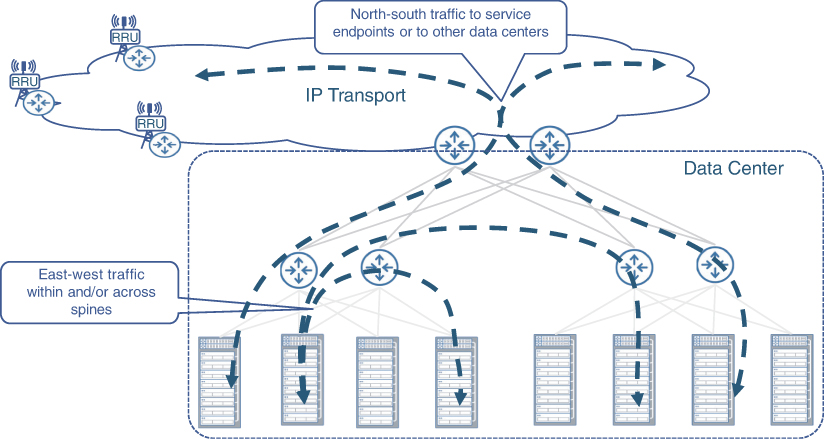
FIGURE 7-4 Overview of Traffic Flows in a Data Center
For these communications to happen effectively, VPN services should be established between various endpoints, whether in the local DC, remote DC, or in the IP transport. This presents some architectural challenges, as the VPN services required to provide this connectivity might traverse both the DC and the IP transport (or rather the xHaul network), which might differ in terms of technologies used to implement these networks. DCs predominantly use a BGP-based L3 infrastructure with a standardized (albeit DC-centric) protocol, such as VXLAN. In contrast, xHaul networks almost always use an IGP (IS-IS or OSPF) along with BGP-based L3 VPNs, or, more recently, Ethernet VPNs. Chapter 8, “Essential Technologies for 5G-Ready Networks: Transport Services,” covers the motivation and significance of using VPN to provide transport services in greater detail.
VXLAN is a standards-based Layer 2 overlay technology for DCs defined in RFC 7348, Virtual eXtensible Local Area Network (VXLAN): A Framework for Overlaying Virtualized Layer 2 Networks over Layer 3 Networks.”15 VXLAN provides data encapsulation at Layer 2 through the use of a virtual tunnel endpoint (VTEP), a router that encapsulates the original L2 frame within a VXLAN header. The L2 VXLAN frame is then forwarded over the L3 network to the remote VTEP, which decapsulates the header and transmits the original frame to its destination. However, VXLAN is a data-plane-only technology that relies heavily on the flooding and MAC learning mechanisms, similar to a traditional L2 network, which, as mentioned many times, have severe adverse effects on the network. One of the major enhancements to the original VXLAN specification is the integration of the EVPN control plane with VXLAN, as specified in RFC 8365.16 EVPN uses the BGP control plane to transmit routing information for L2 endpoints, enabling these endpoints to learn about other EVPN peers and forward L2 traffic using L3 routing information. When used in conjunction with VXLAN, EVPN provides the control plane and L2 endpoint discovery, while VXLAN provides data plane forwarding.
EVPN elegantly separates the control plane and data plane and is flexible in the choice of data plane encapsulations. When used in DCs, it is typically deployed with VXLAN for forwarding, while in an xHaul environment, EVPN is generally used with Segment Routing–based traffic forwarding. In addition to the flexible data plane, EVPN allows for both L2VPN and L3VPN functionality, making it useful in environments where both L2 and L3 VPN connectivity services might be desired. An example of this can include the connectivity between RU and DU, which is implemented as a L2VPN today, whereas DU-to-CU and CU-to-UPF are deployed as a Layer 3 VPN service. The use of EVPN in xHaul networks has been steadily growing, and with its symbiotic relationship with VXLAN, EVPN’s use in 5G networks is expected to continue. Both VXLAN and EVPN are viable mechanisms to implement end-to-end services for 5G-ready networks and are discussed in detail in the next chapter.
Data Center Interconnect (DCI)
As covered in the previous section, east-west traffic (that is, the traffic that does not leave the DC) is the dominant traffic. However, there are also north-south traffic streams that do enter and exit the DC, whether this is to reach a service endpoint such as the mobile subscriber or to provide connectivity between various application endpoints that may reside in different DCs altogether. Some examples of this inter-DC connectivity include the traffic between the DU in a far-edge DC and the CU in an edge DC as well as traffic exchange between UPF and other functions of 5GC located in different DCs as part of CUPS implementation. Another example of such a traffic flow could be the flow of Voice over IP (VoIP) traffic that is transported between the CU in the edge DC and the IMS function, which is typically located in the central DC.
It should be reiterated here that CUPS does not automatically mean that UPF and other functions of the 5GC will be in different DCs; rather it allows this flexibility in an effort to enable mobile service providers either to offload mobile traffic off their network as close to the mobile subscriber as possible instead of transporting all the way to the central DC or to terminate the mobile traffic on a relevant application closer to the user as part of a uRLLC or MEC implementation. Whatever the case may be, data center architecture should accommodate traffic forwarding between multiple data centers. This inter-DC connectivity is called Data Center Interconnect (DCI) and is an integral part of overall network architecture and design.
Typically, there are two dominant choices to implement DCI within a service provider environment: optical/DWDM or IP/MPLS-based packet networks. Both options are widely acceptable within the industry and used as appropriate. When selecting a DCI mechanism, a service provider should consider commonsense factors such as total traffic between the DC, distance limitations, and, obviously, the cost of the overall DCI solution. Purely optical solutions such as DWDM use dedicated fiber links to implement DCI between DCs and are ideal for scenarios where high amounts of data exchange is needed between data centers in different locations. It is a common solution for cloud providers that rely on huge amounts of data continually being exchanged between DC sites.
However, optical and WDM solutions require dedicated fiber connections and lack statistical multiplexing capabilities. All DCs require connectivity not only with other DCs but also to the service provider’s IP transport network to ensure the application in the DC can communicate with the endpoints (for example, mobile subscriber) in the SP’s access domain. This IP-transport-to-DC connectivity might just be a pair of leaf routers, sometimes called a border leaf, providing the interconnect between the IP network and DC spines. Depending on the size of the DC, in some cases, the spines themselves can act as the border leaf, connecting the data center fabric and the IP transport. The service provider, more often than not, uses the same routers that implement the border leaf functions to provide the DCI function as well. This helps keep the cost down by avoiding duplication of devices and connections, but it also utilizes the service provider’s own IP transport network, resulting in extracting as much return on investment from the network as possible. For this to be feasible, the SP must own its own transport infrastructure connecting data centers in different locations. Use of the IP transport for DCI is also very popular in new architectures with far-edge and edge DCs integrated within the transport, unless the SP decides to use a cloud-based DC approach, as covered in the previous section. Generally, most service providers use a combination of DWDM and IP/MPLS-based connectivity to fulfill their DCI needs.
Orchestrating the Data Center Fabric
Design repeatability and ease of deployment are two of the most important and sought-after characteristics of any network deployment. Both of these characteristics contribute heavily toward an efficient and timely network rollout as well reducing the chances of encountering issues during large-scale deployment. This is even more true for DCs, given their scale and quantity in modern networks.
Clos fabric–based DC design solves the repeatability aspect of a design to a large extent. A network architect has to develop the architecture (routing design, QoS and security policies, high availability, and so on) just once using the defined topology, and new ToRs, leafs, or spines can be added to the fabric when needed. The design also acts as a blueprint for any new DC that needs to be spun up as part of the overall distributed DC model.
Ease of deployment does require additional planning as well the use of additional tools and applications. These applications are typically geared toward the automated orchestration of the data center fabric with as little human interaction as possible. Sensing the need and market opportunity, over the past several years, networking equipment manufacturers have intensified their orchestration and automation solution offerings. With mobile service providers regularly opting for multivendor networks, a lot of these tools focus on multivendor orchestration capabilities in addition to a vendor’s own devices and solutions. Some of these tools may focus squarely on DC orchestration such as Cisco’s Data Center Network Manager (DCNM) or Juniper’s Apstra System, while others may be more general purpose such as Network Services Orchestrator (NSO) by Cisco and NorthStar by Juniper.
Multivendor capabilities are such an important part of today’s automation and orchestration ecosystem that traditional networking equipment providers are creating, either in-house or through acquisition, semi-independent companies solely focused on generic automation and orchestration. Examples of this include Tail-F, Blue Planet, and Nuage—all of which are software-focused automation, orchestration, and management companies, but owned by Cisco, Ciena, and Nokia, respectively. Using such an arrangement allows these solutions to create the impression of a multivendor, generic solution instead of being focused on a particular vendor. This practice promotes solution neutrality to a certain extent and benefits the customers and networking industry in general.
Orchestration is the key for any networking solution and offers a quick, efficient DC deployment through the use of various automation and orchestration tools. Automation is a topic worthy of a publication of its own, and this book uses the concept of automation as it pertains to the network deployment and implementation. Note, however, that all automation and orchestration solutions rely heavily on a robust, repeatable, and extensible underlying architecture. Using a Clos fabric design with a uniform architecture across DCs (small, medium, or large) allows service providers to use orchestration solutions without the need to create custom automation for every single deployment.
Optimizing Compute Resources
With the massive use of the general-purpose COTS hardware in today’s large-scale DCs, the efficient and optimal use of these hardware resources becomes an important consideration. The optimization is required for energy efficiency, application performance, and cost reduction. This section aims to outline the need for resource optimization as well as covers commonly used optimization techniques in data center environments.
Why Optimize?
The unprecedented growth of cheap computational power and the emergence of large DCs might create the impression that any computational challenge can be solved by installing faster central processing units (CPUs) and throwing in more computational resources at the task. Although this extensive approach results in a quick growth of computational power, it also inflates the cost and power required for such a solution. Moreover, certain types of computational tasks do not benefit from running on massively parallel systems, and while custom-designed application-specific integrated circuits (ASICs) and field-programmable gate arrays (FPGAs) can provide a viable solution in such cases, they lack flexibility when a change in algorithm is required. ASICs and FPGAs might outperform general-purpose CPUs in tasks they are designed for and can be energy efficient. Yet, in order to provide a reasonable level of flexibility, they are typically used as expansion modules while the general-purpose CPUs remain the main engine of today’s commercially available server hardware.
In today’s highly virtualized world, with its innumerable virtual machines, containers, and applications running on shared compute resources, the importance of optimizing the use of computational resources can hardly be overestimated. Due to the sheer number of servers running in a typical DC or in the whole MCN, any inefficiency in computational resource utilization results in significant wastage of power, cooling, and space—and, ultimately, money. Microprocessor and server manufacturers do recognize these challenges and offer a variety of features to increase the power efficiency of their solutions. Indeed, scaling down the clocking speed for idle or underutilized CPU cores, use of low-power modes for both CPU and memory (when not actively used), CPU dynamic voltage control, and other features help to reduce each individual server’s power consumption. Nevertheless, these features can cause unintended consequences if implemented without proper consideration for the requirements of actual applications and virtual functions.
Common Optimization Techniques
Virtual functions running in today’s DCs can have specific and diverse expectations on memory and disk access latency as well as available CPU cycles. Failure to satisfy these expectations might cause severe instabilities in code execution, and even result in an application crash. Such instabilities are extremely hard to troubleshoot, as they might happen in the absence of obvious signs of a system overload, such as high CPU load or lack of free memory resources. Optimizing the use of compute resources helps to prevent instabilities and avoid costly side effects of resource overprovisioning, while allowing for safely engaging power-saving features of modern computational hardware.
In simple terms, any application code execution relies on pulling data from memory, performing desired operations on it using CPU, and storing the result in memory again. Modern high-performance CPUs are based on extremely complex architectures featuring multiple cores, low-latency cache memory, and memory controllers on a single die. A few such CPUs can be installed in a typical server, hosting various VMs and applications, and while they provide plenty of computation resources, memory access is far from being simple on such systems.
A typical commercially available server usually supports multiple physical CPUs with plenty of memory slots. In these multi-CPU systems, all memory slots are divided into groups, with each group connected directly to only one physical CPU, referred to as a CPU package. A CPU designed for use in multi-CPU servers has its own memory controller performing read and write operations from/to the random-access memory (RAM) connected to it. At the time of this writing, server CPUs support up to two memory controllers on a die, each providing up to four channels of memory connections.17 Multichannel memory access allows for parallelizing memory operations, and reading or writing more data at once without queuing requests from multiple CPU cores, thereby reducing memory access latency dramatically. However, operating systems (OSs) or hypervisors supporting multi-CPU systems allow any core on any CPU package to access all memory, connected to all CPU packages. Thus, it is entirely possible for a process to be executed by a core on one CPU package, while using data residing in memory connected to another CPU package. Server CPUs, supporting multi-CPU configurations, have special inter-CPU links to exchange data in such scenarios. These inter-CPU connections, however, have less bandwidth compared to that of memory controllers, and accessing memory resources connected to other CPU packages introduces significant latency. Such multi-CPU systems are called non-uniform memory access (NUMA) systems, reflecting the fact that access to local and remote memory resources is not uniform. In a NUMA system, each CPU package (and its connected memory banks) is called a NUMA group. Figure 7-5 shows a NUMA system consisting of two NUMA groups.
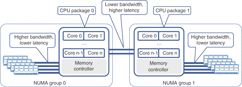
FIGURE 7-5 Multi-CPU NUMA System
Virtually all operating systems and hypervisors today support multi-CPU systems, and their CPU schedulers are designed to run effectively on NUMA systems. Nevertheless, OS and hypervisor schedulers have to find a balance between efficient load distribution of different processes across all available cores, and memory connectivity specifics in a NUMA system. The algorithms, employed by CPU schedulers, do well in many scenarios, but under certain conditions they might struggle to allocate resources optimally. For example, a guest OS running in a VM uses its own CPU scheduler to run multiple processes on virtual CPUs allocated to it by a hypervisor. The hypervisor, in turn, uses its own CPU scheduler to properly distribute the load from multiple VMs over all available CPU cores. Although the hypervisor’s CPU scheduler is well aware of the NUMA system details it is running on and generally tries to allocate CPU and memory resources on the same CPU package, it might not always be able to do so, depending on the processing power demanded by other VMs. The guest OS could end up scheduling a process on one NUMA group while using memory resources from another. In such an undesirable scenario, a process can experience higher and sometimes unpredictable memory access latency, which can result in instabilities and process crashes.
Proper sizing of VMs can be considered a good practice to prevent such scenarios. A VM overprovisioned with virtual CPUs and memory resources that cannot be accommodated by a single CPU package will likely end up running on multiple CPU packages with the negative effects described previously. However, even a properly sized VM could still end up running on multiple physical CPU packages, depending on how loaded the system is and the number of other VMs running concurrently. Configuring affinity values for VM CPU resources, also known as CPU pinning, instructs the hypervisor or OS schedulers to use only specific physical CPU cores or packages to schedule tasks. This technique is very effective in preventing the scheduling of VM computations on different physical CPU packages. Depending on implementation, memory allocation may follow CPU assignments automatically or can be configured with an affinity value to stick to a certain CPU package as well, thereby avoiding unnecessary latency in accessing data in memory.
Besides multiple physical cores, modern CPUs also allow execution of multiple (usually two) application threads in parallel on each physical core, using the Simultaneous Multi-Threading (SMT) feature (Intel’s implementation of SMT is called HyperThreading, or HT).18 This feature presents a logical equivalent of a core to the operating system/hypervisor. Although actual operations are executed on a single physical core, in many scenarios it is beneficial to treat a single physical core as two logical cores and run more than one parallel application threads simultaneously. CPU schedulers in today’s hypervisors allow operators to choose between treating SMT-enabled CPU cores as multiple logical ones and mapping the whole physical core to a VM’s virtual CPU.
The use of FPGAs and ASICs in expansion cards can provide great benefits for faster and more energy efficient computational tasks. One example of such technology is the Stateless Offload (a.k.a. TCP Offload Engine), which takes the load of calculating TCP, UDP, and IP checksums off the CPU. Another example of offloading computationally intensive tasks to specialized FPGAs is Intel’s FPGA-based hardware Layer 1 FEC accelerator. It can offload FEC calculations in 4G and 5G applications from the server’s general-purpose CPU, thus facilitating the hosting of RAN components such as DU and CU on these commercially available servers.19 In fact, all the resource-optimization techniques discussed are essential in product design for various 5GC functions or RAN nodes in an effort to provide an effective transition from hardware-based to virtual and cloud-native solutions for MCN.
Power efficiency requirements for edge and far-edge DCs further propelled the search for more efficient computational solutions to host DU and CU functions. In particular, far-edge DCs might have very strict constraints on power and cooling provisions while hosting computationally intensive DUs. Use of graphics processing units (GPU) can provide vast floating-point calculation capacity for mMIMO and mmWave applications, while reducing power consumption in comparison to general-purpose CPUs. Major radio vendors and GPU manufacturers are already exploring these new possibilities for building energy-efficient and powerful DUs.20
The real-time baseband processing nature of the DU functions presents challenges for conventional computational systems. To solve this, chip manufacturer Intel has been promoting a reference architecture called FlexRAN that uses a combination of hardware enhancement (such as accelerator cards) and associated software stack for efficient and low latency processing of baseband traffic while using generic compute hardware21 The FlexRAN architecture is based on Intel’s x86 processor family and uses what is called a “lookaside” approach. In the lookaside approach, CPU performs the bulk of the functions while offloading some tasks to the hardware accelerator resulting in multiple data exchanges between the CPU and the accelerator. In other words, the CPU “looks aside” to the hardware accelerator when needed. Intel’s FlexRAN has been the only choice for vRAN implementation so far. More recently, however, another approach referred to as “inline acceleration” has been introduced by ASIC manufacturers such as Qualcomm and Malinox. The inline acceleration approach hands off the traffic from CPU to ASIC only once, and relies on it to perform all the baseband data processing functions thus reducing dependency on the CPU22. Though this has been demonstrated using peripheral cards on x86 based compute systems, this is viewed as a possible shift from dependency on x86 based CPUs and Intel’s FlexRAN architecture.
Summary
This chapter explored the fundamentals of DC networking as an essential building block of an end-to-end 5G mobile communication network.
This chapter covered the following DC-specific topics:
Origins and evolution of large-scale DCs along with various DC models such as on-premises (on-prem) DCs, co-location DCs or co-location racks, managed hosting services, and public cloud
The use of Clos-based fabric as a basic DC building block and the concepts of spine and leaf in a data center fabric
The ongoing transitions from centralized to distributed and cloud-based DC deployment models
Routing and switching technologies within a DC as well as traffic flows and connectivity mechanisms for inter-DC communication as well as connecting DCs to the IP transport network
The importance of automation and orchestration of the data center fabric
The importance of, and some of the commonly used optimization techniques for compute resources in the DCs used for MCN
The next chapter will dive further into the essential technologies and focus on service deployment for end-to-end (E2E) connectivity between various components of the mobile communication network. It will cover the protocols and technologies that enable E2E services across the MCN domains.
References
1. https://www.crn.com/news/data-center/microsoft-to-build-new-200m-data-center-as-azure-sales-soar (last visited: Mar 2022)
2. https://www.microsoft.com/en-us/research/wp-content/uploads/2009/06/2009-06-19-Data-Center-Tutorial-SIGMETRICS.pdf (last visited: Mar 2022)
3. https://www.ieee802.org/3/hssg/public/nov06/diminico_01_1106.pdf (last visited: Mar 2022)
4. Morgan Stanley Research, “Technology Eating the World—Top Trends Post COVID-19,” https://advisor.morganstanley.com/the-irvin-and-bevack-group/documents/field/i/ir/irvin-and-bevack-group/12%20Top%20Tech%20Trends%20Post%20COVID-19%206%2017%2020.pdf (last visited: Mar 2022)
5. AT&T web hosting services, https://webhosting.att.com/ (last visited: Mar 2022)
6. Morgan Stanley Research, op. cit.
7. https://ia801901.us.archive.org/8/items/bstj32-2-406/bstj32-2-406_text.pdf (last visited: Mar 2022)
8. https://news.microsoft.com/innovation-stories/project-natick-underwater-datacenter/ (last visited: Mar 2022)
9. Caser Wu and Rajkumar Buyya, Cloud Data Centers and Cost Modeling, (Waltham, MA: Morgan Kaufmann), 2015
10. https://aws.amazon.com/wavelength/ (last visited: Mar 2022)
11. https://aws.amazon.com/outposts/ (last visited: Mar 2022)
12. https://azure.microsoft.com/en-us/overview/azure-stack/#overview
13. IEEE RFC 6326, “Transparent Interconnect of Lots of Links (TRILL) use of IS-IS”
14. IEEE RFC 7938, “Use of BGP for Routing in Large-Scale Data Centers”
15. IEEE RFC 7348, “A Framework for Overlaying Virtualized Layer 2 Networks over Layer 3 Networks”
16. IEEE RFC 8365, “A Network Virtualization Overlay Solution Using Ethernet VPN (EVPN)”
17. https://www.intel.com/content/www/us/en/products/docs/processors/xeon/3rd-gen-xeon-scalable-processors-brief.html (last visited: Mar 2022)
18. https://www.intel.com/content/www/us/en/gaming/resources/hyper-threading.html (last visited: Mar 2022)
19. https://builders.intel.com/docs/networkbuilders/virtual-ran-vran-with-hardware-acceleration.pdf (last visited: Mar 2022)
20. https://www.ericsson.com/en/blog/2020/2/virtualized-5g-ran-why-when-and-how (last visited: Mar 2022)
21. FlexRAN™ Reference Architecture for Wireless Access - https://www.intel.com/content/www/us/en/developer/topic-technology/edge-5g/tools/flexran.html (last visited: Mar 2022)
22. How to build high-performance 5G networks with vRAN and O-RAN? https://www.qualcomm.com/media/documents/files/how-to-build-high-performance-5g-networks-with-vran-and-o-ran.pdf, Slide 15 and 16 (last visited: Mar 2022)