Chapter 1
A Peek at the Past
From social media check-ins during a beach vacation to geo-tagging and uploading photos of a trekking adventure or answering a critical call from your mobile device during a desert safari, it is expected that the network will always be there, providing continuous connectivity to fulfill what are now considered to be regular, everyday tasks.
Ubiquitous mobile connectivity is not just a requirement but rather an expectation in today’s mobile services landscape. The flexibility and usability enjoyed by a vast majority of mobile users daily have been a result of multiple decades of innovation in mobile communication technologies as well as the underlying network infrastructure that supports it. Over the past few decades, multiple generations of mobile technologies have been adopted globally, each one of them enabling new possibilities for the mobile users. This chapter briefly looks at the pivotal changes in mobile communication over time to understand how the mobile services were shaped through various generations.
Brief History of Pre-Cellular Mobile Networks
Starting from the initial systems using circuit-switched analog voice, mobile communication systems have gone through multiple generations of evolution—from 1G all the way to 5G. That’s an average of a generational leap every decade, compared to a century-long initial leap from fixed-line to mobile communications. Each generation brought revolutionary changes and enabled new use cases that catalyzed rapid embrace of the technology, slowly laying the foundation of what we know today as 5G. To truly appreciate 5G, and more importantly to understand the technology, it’s essential to take a look at the evolution in the previous generations of mobile telephony.
The very first mobile telephony networks were built using the well-known concepts of a broadcast radio network. The goal of these mobile communication networks was to be able to provide the ability to make and receive phone calls while on the move. The pioneers of the mobile telephony service followed the seemingly straightforward approach of using a single service area—inline with radio broadcast methods.
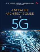
Mobile Telephone Service (MTS), introduced in 1946, can be considered the very first mobile communication system. MTS was deployed using a single omnidirectional transmitter that covered the whole service area. The service was limited by the technology of its time, with the central transmitter’s location, power, and usable frequency spectrum restricting the coverage distance and capacity. Additionally, the mobile radio telephone units had limited power at their disposal for transmitting back to a central receiver. The mobile telephone units used at the time were not the miniaturized, technically sophisticated devices that we use today, but rather a bulky piece of equipment, weighing several pounds and drawing power from the car or truck they were typically installed in.
To accommodate for this lack of transmitting power in the mobile telephone units, multiple receiving antennas were strategically placed to improve the stability of signal reception from mobile users. The mobile telephone unit would receive the signal from the main transmission tower; however, return signals were relayed back through the receiver closest to the end user.
Frequency Spectrum and Channels
The air interface of a mobile network uses specific frequencies for communication. Because frequencies available for communication are limited, their use has been regulated. To avoid interference, mobile operators need to have a specific frequency range allocated to them for their dedicated use. A frequency spectrum refers to the range of frequency available for a system to transmit and receive on.
Mobile operators may internally split the frequency spectrum into sub-ranges, to allow multiple simultaneous communication to take place. These frequency ranges are referred to as channels.
Due to the limited number of channels available in the frequency spectrum, MTS allowed just a handful of simultaneous calls from subscribers in the service area. MTS did not allow two-way speech either, and only one person on the voice call could talk at a time by pressing and holding the talk button. Despite its shortcomings, MTS systems were widely used due to the attractive nature of mobile communication. The air interface provided by MTS was merely an extension of the Public Switched Telephone Network (PSTN). When an MTS subscriber wanted to make a call, they would first have to manually check for mobile channel availability to reach the operator. The operator would then use the PSTN to connect the MTS call. Figure 1-1 provides a high-level overview of MTS. As shown in the figure, multiple MTS service areas could connect to each other using PSTN as their backbone. Within each MTS service area, the user’s mobile device communication was split between the central transmitter (Tx) and the receiver (Rx) closest to the device. In the central exchange, an operator would assist in completing the call through PSTN.
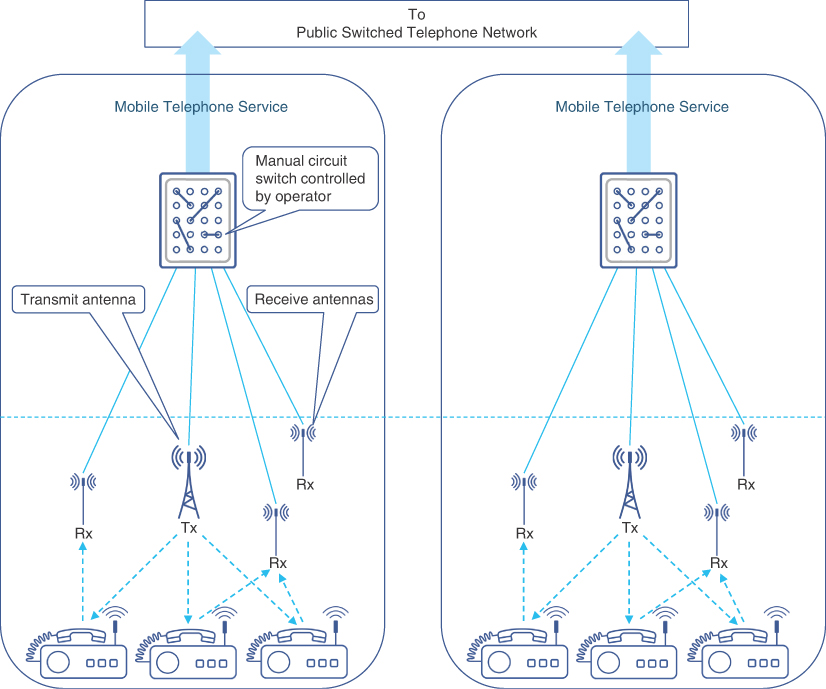
FIGURE 1-1 Mobile Telephone Service (MTS) Overview
MTS left a lot to be desired, and during the 1950s and 1960s, many incremental improvements were made. The Improved Mobile Telephone Service (IMTS) was introduced in 1964,1 which allowed more simultaneous calls by using additional frequency channels that were made available as well as introduced auto-dialing capability. IMTS also brought auto-trunking, which meant that subscribers no longer had to manually search for an available voice channel. While IMTS allowed for higher subscriber scale, it was still very much limited. By the mid-1970s, Bell’s IMTS offering in New York City consisted of 543 paying customers, with a waiting list of 3,700 people.2
The mobile service offering had proved its market viability, but technology limitations severely handicapped widespread adoption of mobile services. Some of the challenges were as follows:
Geographically limited service area due to the use of a single transmitter for a whole service area.
Small number of channels in the available frequency spectrum, resulting in a limited number of subscribers.
Mobile telephone units required a significant amount of power to transmit radio signals. Nearly all IMTS mobile units were automobile based and used large batteries to provide the desired power levels, making true mobility harder and more cumbersome to achieve.
These limitations, among others, required a fundamental change to the underlying principles of mobile networks. A new approach to arranging the service area into small cells promised to change the mobile telephony landscape, introducing the concept of cellular service as we know it today.
The Very First Cellular Networks: 1G
While MTS and IMTS were gaining a foothold in the mobile telephone market during the 1950s and 1960s, major telecommunication service providers were working on developing techniques to expand their service area and increase capacity. Figure 1-2 shows an overview of 1G network architecture, outlining major components such as the Mobile Switching Center (MSC), which provided call processing, as well as the Home Location Register (HLR) and Visitor Location Register (VLR), which were used to store information about local and visiting mobile subscribers. These components are discussed in greater detail later in this chapter.
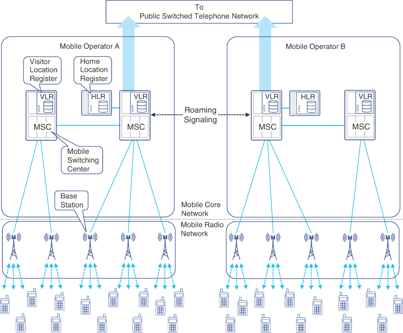
FIGURE 1-2 High-level Overview of 1G Mobile Network Architecture
The 1G cellular network for North America was developed and marketed as the Advanced Mobile Phone Service (AMPS) system, whereas the European equivalent was labeled Total Access Communication System (TACS). TACS was further adopted as European TACS (ETACS) in select European markets and as Japan TACS (JTACS) in Japanese markets.3 Both AMPS and TACS were virtually similar in architecture and principles but used different frequency spectrums and carrier channels, as discussed in the “Choosing the Right Frequency” section in Chapter 2, “Anatomy of Mobile Communication Networks.”
Another 1G analog mobile communication network worthy of mention is the Nordic Mobile Telephone (NMT) system. Originally developed by and used in Scandinavian countries in the early 1980s, it quickly expanded to the rest of the Nordic region, the Baltics, the rest of Europe, Turkey, and Russia. NMT was one of the most widely adopted 1G networks outside of North America and a precursor to the development of 2G specifications.
From a network engineer’s perspective, 1G network architectures introduced three main functional domains:
Mobile Radio Networks
Mobile Transport
Mobile Switching Center (MSC)
Innovations in Radio Access
As mentioned in the previous section, a single mobile transmitter and large service areas impeded the progress of the mobile telephone service. To address this challenge, AT&T Bell and other telecommunication providers introduced the concept of using multiple antenna towers within a geographical service area.4 Each antenna tower provides transmit and receive functions for a smaller coverage area, dubbed a “cell.” The antenna tower, known in 1G as a base station (BS), is at the heart of each of these cells, and multiple BSs could be placed strategically to form a cellular network throughout the desired service area. Figure 1-3 illustrates this concept.

FIGURE 1-3 Cellular Radio Network Representation
Figure 1-3 shows multiple transmission stations, each covering a smaller area (or “cell”), which provided a simple, scalable, and extensible solution to the limitations of MTS and IMTS. Now mobile (or rather cellular) service subscribers were more likely to be in close proximity of a base station (BS) throughout the coverage zone. Using this approach, more “cells” could be added to the network, thus easily expanding the service coverage area if required.
While this cellular approach addressed some of the problems in the original MTS-based mobile design, it introduced the problem of radio wave interference between neighboring cells. The pictorial representations of a cellular network give an illusion of clean radio coverage boundaries between cells, but the reality is not so. Radio waves transmitted from base stations travel through the cell coverage area, but they do not magically stop at theoretical cell boundaries. The cell boundaries are rather amorphous, where cellular signal from adjacent base stations overlap each other (as shown by circular shapes in Figure 1-3). This results in signal interference, thus distorting the signal and sometimes making it harder for the user handset to extract meaningful information from it.
Cellular vs. Mobile
Because the use of cells is a foundational concept in land-based mobile networks, starting from the very first generation, the terms cellular network and mobile network are often used interchangeably when describing mobile communication networks.
Adjusting the transmission power could help minimize this interference but does not eliminate it. The problem was solved by using non-overlapping frequency ranges in neighboring cells. The solution encompassed dividing the available frequency spectrum into smaller ranges, and then using one of these subdivided frequencies in each cell. The same subdivided frequency spectrums can be reused in multiple cells, provided the cells have sufficient geographical separation among them to avoid service-impacting interference from neighboring cells. Figure 1-4 shows the various frequency reuse patterns, where each unique frequency range is represented by a number. Clusters of 4, 7, or 12 frequencies are commonly used frequency reuse patterns. These patterns can be repeated over a larger geography, thus allowing for expanded coverage area using the same frequencies.

FIGURE 1-4 Frequency Reuse Examples
It must be noted that Code Division Multiple Access (CDMA), an air-interface access method, uses a different principle. CDMA uses special codes that allow reuse of the same frequency across all cells. CDMA is further explained later in the section, “Third Generation (3G).”
An Introduction to Mobile Transport
While the cellular network concept made it easier for the user equipment to communicate with geographically disperse base stations, it also highlighted the need for a robust mobile transport. The system now required a transport mechanism to connect these distributed cellular base stations to the central exchange. In the case of early 1G networks, all base stations within the coverage area were directly connected to the central exchange, typically using analog leased lines. Virtually all the 1G network systems were developed independently and used proprietary protocols over these leased lines for communication between the base station and MSC. This could be considered the very first mobile transport network, and although the underlying protocols and communication mechanisms have evolved significantly over the years, the fundamental concept of a mobile transport originated from these very first 1G networks.
Emergence of a Mobile Core
The base stations used a point-to-point connection to the exchange or central office within the coverage area. This central office, referred to as the Mobile Switching Center (MSC), provided connectivity services to cellular subscribers within a single market. The MSC performed its functions in conjunction with other subsystems located in the central office, including the following:
Home Location Register (HLR): A database that contained the information of all mobile users for the mobile operator.
Visitor Location Register (VLR): A database that temporarily stored the subscriber profile of mobile users currently within the coverage area serviced by the MSC.
Authentication Center (AuC): This subsystem provided security by authenticating mobile users and authorizing the use of mobile services.
The MSC was responsible for all functions in the 1G cellular network, including the following:
User authentication and authorization: Done through the AuC subsystem using the HLR.
Security and fraud prevention: Done by comparing locally stored phone data in the AuC’s Equipment Identity Register (EIR) with equipment information received. This helped the MSC deny services to cloned or stolen phone units.
Cellular subscriber tracking and mapping to base station within its coverage area: Each base station would provide the MSC with this information for subscribers associated with that base station.
Voice call connectivity, including local and long-distance calls: Any calls between cellular subscribers within the coverage area were connected directly through the MSC, while call requests to cellular subscribers in other coverage areas or to traditional PSTN subscribers were routed through the PSTN network. Using PSTN as the backbone ensured universal connectivity between all cellular and traditional land-line subscribers.
Subscriber handoff between different base stations: This was assisted by the MSC, which constantly kept track of subscriber signal strength received through base station(s). When the MSC determined that the subscriber signal was stronger from a base station different from the one that subscriber was currently registered to, it switched the subscriber to the new base station. In cellular terminology, this process is known as a handoff. In 1G networks, cellular handoff was initiated by the MSC, as shown in Figure 1-5.
Roaming between different MSCs: This refers to both roaming within the mobile provider coverage zone (intra-operator roaming) and roaming between different mobile providers (inter-operator roaming). Initially, inter-operator roaming and registration was a manual process, but it was subsequently replaced by automatic registration.
Billing: Billing was also managed by the MSC as it kept track of all subscribers, their airtime usage, and call type (such as local or long distance).
Figure 1-5 shows a local cellular handoff within an MSC service region as well as a subscriber roaming between different MSC regions, including both inter-operator and intra-operator roaming.
FIGURE 1-5 Subscriber Handoff and Mobile Roaming
1G cellular networks provided a robust framework for scalable mobile telephony services. Cellular radio access network, mobile transport from base station to MSC, and modular functional blocks within the MSC provided an architecture that laid the foundation for subsequent generations to build upon. Because the MSC was handling all the major functions of managing and monitoring of user devices as well as call control functions, it limited the overall scalability of the mobile system. Second generation (2G) mobile architecture aimed to address these limitations.
Second Generation (2G) Cellular Networks
The first generation cellular network was a great success, but its wide-scale adoption was limited by several factors, including the following:
1G used analog voice modulation inherited from land-line telephony, which resulted in higher transmit power requirements for the handset as well as higher bandwidth requirements. The consequences were the need for bigger, bulkier handsets with limited talk time and a limited number of available voice channels through the air interface.
The MSC was handling call processing, inter- and intra-operator roaming, as well as base station management, which created a resource bottleneck.
Initially the focus had been on voice-based communication. Though data transmission was not a pressing need at that time, the interest to be able to transmit non-voice information was definitely there.
The information in the user handset was hard-coded and didn’t give the user flexibility to switch devices easily. For vendors, that meant a barrier to a market opportunity.
As digital voice encoding and transmission were replacing analog voice in telephony networks, the mobile industry saw the huge benefits it could bring. There was also a desire to offload some of the MSC functionalities to remove the resource bottleneck and achieve better scale. These motivations resulted in the evolution toward the second generation (2G) of cellular mobile communication, which introduced enhancements in every functional domain of the cellular network.
Different geographies and markets ended up with different variations of 2G implementations. Digital AMPS (D-AMPS), Global System for Mobile Communications (GSM), and Interim Standard 95 (IS-95) were some of the 2G implementations in the early and mid-1990s.
2G Innovations in Radio Access
2G introduced a number of technical enhancements over its 1G counterpart, primarily focused on providing ease of use and scaled services through digital modulation, multi-access, enhanced security, and handset flexibility.
Use of Digital Voice
2G systems were designed to use digital encoding of voice and digital modulation for transmission. Use of digital transmission not only improved voice quality significantly but also increased spectral efficiency through encoding and compression.
The air interface in 2G was designed to use Common Channel Signaling (CCS). CCS could “steal” some of the bits from the encoded voice and use it for signaling between the user and the base station. This made it possible for a user to be on a voice call while still being able to exchange information with the base station for providing value-added services such as call waiting.
Improved Multi-Access Scale
North American and European 2G efforts adopted different techniques for multi-access—that is, allowing multiple mobile users to communicate at the same time. The European implementations favored Time Division Multiple Access (TDMA) techniques by offering separate time slots to the mobile devices. Global System for Mobile Communications (GSM) emerged as the predominant European standard and was built on TDMA.
North American implementations were split between use of TDMA (for D-AMPS implementations) and Code Division Multiple Access (CDMA) based deployments. CDMA was also a popular choice in the Asia-Pacific region.5
Handset Flexibility
GSM introduced the subscriber identity module (SIM) card—a small memory card that could store key information related to a mobile user’s identity. SIM cards made it possible for a user to change their handset while porting the identity and credentials to the new device. The handsets no longer needed to be tied to a mobile provider but could now be a generic device made to GSM specifications. The handset could communicate with the GSM network by using the information stored in the SIM card. The use of SIM cards opened up a new market opportunity to handset manufacturers as well as offered subscribers the flexibility to change their handset as often as desired.
Security Considerations
Privacy and security had always been a concern in mobile communication. The communication through air interface could easily be sniffed without the sender and recipient learning about it. Setting up a “man in the middle” (MitM) and hijacking a communication was also not very difficult either. The shift from analog to digital voice made it slightly harder to sniff the communications but didn’t make it any more secure. 2G standards, especially GSM, started to implement key-based encryption of the encoded voice. This offered some level of privacy to the mobile communication.
2G Mobile Transport
In order to provide a more efficient and scalable network, 2G introduced the concept of a base station controller (BSC). Now, instead of a direct point-to-point connection from each base transceiver station (BTS) to MSC, multiple BTSs would connect to a BSC that provides connectivity to MSC. The BTS in 2G was the equivalent of a base station (BS) in 1G. Figure 1-6 provides an overview of the end-to-end 2G mobile network.
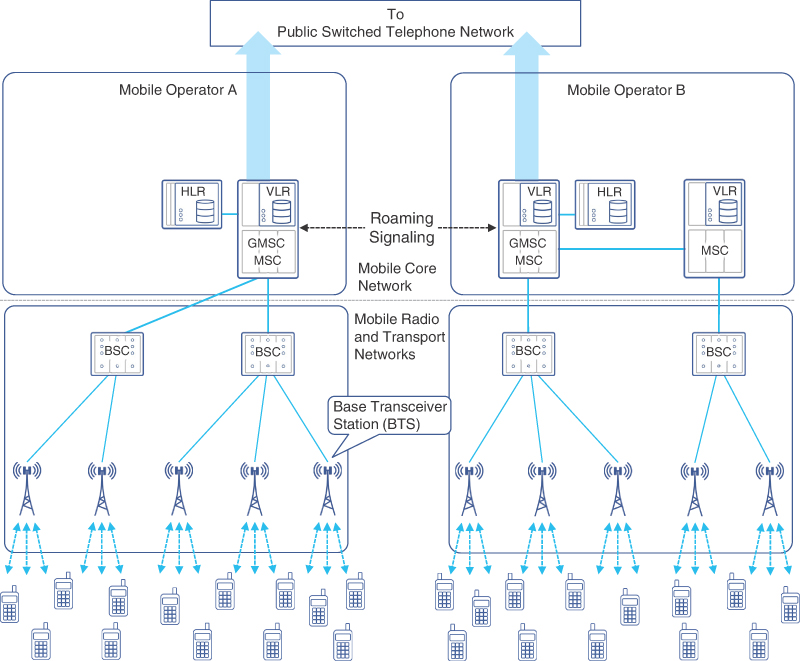
FIGURE 1-6 2G Mobile Network Architecture
As shown in Figure 1-6, multiple BSCs acted as an aggregation point for a group of BTSs. The physical link between the BTS and BSC was a full or fractional T1 or E1 link, with specialized protocols for communication between the two. The control functions of the BTS, such as frequency channel allocation, user signal level measurement, and cellular handoff between BTSs (previously the responsibility of MSC), were now handled by the BSC.
Visitor MSC (V-MSC) and Gateway MSC (G-MSC)
MSCs in 2G networks have the responsibility to manage multiple BSCs. These MSCs are interconnected and can route calls to and from the mobile handsets that are registered to it. For calls that originate from or terminate at networks outside the mobile provider’s network (for example, PSTN or other mobile providers), a small subset of these MSCs has connectivity to external networks and act as a gateway to those networks. Consequently, these MSCs are referred to as the Gateway MSC (G-MSC), as shown in Figure 1-6. The MSC where a mobile subscriber is registered is referred to as the Visited MSC (V-MSC) for that subscriber. The G-MSC still serves as the V-MSC for the BSCs it manages, but it performs the additional function of acting as a gateway to external networks.
Modular transport provided extensibility to add a new BSC and/or BTS when desired. As the BSC acted as an aggregator for multiple BTSs, the architecture allowed the MSC to scale better by controlling more BTSs using the same number of links. Additionally, depending on the vendor, the BSC also provided switching center capabilities, thus further reducing the load at the MSC. BSCs were connected to the MSC using Frame Relay over full or fractional T1/E1 links.
2G Mobile Core
With the introduction of the BSC, some 2G networks, such as GSM, started to distinguish between the radio network and the switching network. The terms base station subsystem (BSS) and network switching subsystem (NSS) were introduced to highlight this architecture. The BSC and BTS functions belonged to the BSS, while MSC and the databases it used collectively comprised the NSS, performing all validation and switching functions. This distinction led to how the mobile networks are architected today; NSS evolved into the mobile core, and BSS evolved into radio access network (RAN). The transport network providing the connectivity between the RAN and mobile core evolved into what is commonly known as the mobile backhaul.
The 2G mobile core offered a number of key enhancements over the previous generation in terms of efficiency, interoperability, and services, some of which are covered here.
An Efficient Mobile Switching Center
2G improved MSC scalability and operational efficiency by splitting some of the MSC functions and moving them to the newly introduced BSC. As previously explained, the role of BSC was to communicate with a group of BTSs, facilitating their functioning and coordination, as well as to work with the MSC for authorization, billing, and voice communications. Functions such as HLR, VLR, and PSTN connectivity stayed within the MSC.
One of the functions that BSC offloaded from MSC was the capability to perform most of the handoffs between base stations. Because multiple BTSs were connected to the same BSC, if a mobile user moves between BTSs connected to the same BSC, the handoff is handled locally at the BSC. However, a handoff between a BTS controlled by different BSCs was still handled by the MSC. These BSC-based handoffs helped the network perform better by reducing handoff times and saving resources on the MSC.
Step Toward Standardization
With the architectural changes and introduction of new components (such as BSC), there was also a subtle move toward standards-based communication between network components. As such, the MSC-BSC interfaces were standardized—a small but significant step toward vendor interoperability and multivendor networks.
In Europe, the market size and geography didn’t make it practical for each country to develop its own mobile communication systems. The European Telecommunication Standards Institute (ETSI) helped develop a common communication standard across Europe under the marketing name Global System for Mobile Communications (GSM). This was a significant step toward standardizing communication protocols across countries.
New Text and Data Services
GSM allowed the use of voice channels for low-rate-data transmission as well. Just like PSTN dialup, 2G GSM handsets would use a built-in modem to establish a data connection over the voice circuit. While this was not very efficient (it would take time to establish the connection, the subscriber couldn’t use voice service while the data session was active, and data rates were awfully low), it was still an improvement compared to the “voice-only” capability in 1G.
Another popular service was Short Message Service (SMS), which could allow exchange of short (up to 160 characters) messages between the users. SMS used control channels between existing network components, and hence no new messages/protocols were required for this value-added service. This provided a monetization opportunity for operators by offering SMS add-on service to their subscribers.
2G Technology Summary
2G development was an interesting time in mobile standardization and adoption, as multiple technologies were competing in standard bodies as well as in the marketplace. GSM quickly emerged as the dominant market force owing to its widespread adoption in the European market. GSM emerged as the major 2G mobile standard; its users could get “roaming service” in multiple countries and could easily switch handsets using SIM cards. All these “features” propelled GSM to frontrunner status in the race for mobile dominance.
At the turn of the century, GSM had more than two-thirds of the market share compared to rest of the mobile technologies, with over 788 million subscribers in 169 different countries.6
Generation Two and a Half (2.5G)
As previously mentioned, 2G/GSM used time-based multiplexing, in which a timeslot is allocated for a user’s communication. These timeslots, over the duration of the call, create a logical channel for this user called the traffic channel (TCH). The end-to-end connection was established by using a TCH on the shared air interface. Figure 1-7 shows the mapping of a TCH to allocated timeslots for the duration of a call.

FIGURE 1-7 Timeslot-to-TCH Mapping
Even though 2G/GSM had made it possible to establish a data connection, it was at the cost of sacrificing the user’s entire TCH. The TCH would remain occupied for the entire duration of the connection, thus making the underlying timeslots unavailable for any other use. While both data and voice kept the TCH circuit occupied for that particular user only, the fundamental difference between the nature of voice versus data calls made dedicated TCH not an optimal choice for data connections. Most voice calls tend to be brief, and the TCH/timeslots would then be freed up for use by other subscribers. On the other hand, a data connection might be for a much longer duration, making underlying timeslots unavailable for users to establish a new TCH.
In the mobile core, a data connection is established using a circuit switched network that was originally meant for voice. This circuit switched data inherited the same problems as PSTN dialup in terms of speed and connectivity. This combination of circuit switched data with dedicated TCH made it inefficient for activities such as email and web browsing, which work best with always-on connectivity. Besides, a single timeslot could offer only 14.4Kbps of data transmission rate, which by modern standards is, well, slow. 2G/GSM did allow concatenation of multiple timeslots to provide a single high-speed communication channel of up to 57.6Kbps per mobile station. This offered slightly higher speeds; however, the drawback was that these concatenated timeslots were now consumed by a single user exclusively, resulting in others being starved of resources for voice and/or data calls. As one can guess, a single user utilizing multiple dedicated timeslots for data was rather impractical and couldn’t satisfy growth.
2.5G enhanced GSM standards by adding a new functionality called General Packet Radio Service (GPRS) in the year 2000. This was meant to facilitate packet transmission (that is, data transmission) over a mobile network. Instead of allocating all the timeslots for voice channels, as was originally done in GSM, GPRS allowed for carving out a small number of timeslots for data transmission purposes. Instead of occupying timeslots for the whole duration of the session, these data timeslots were made available to users only when they had data to transmit or receive, thus taking advantage of statistical multiplexing. As a consequence, users could now be charged for the data exchanged and not based on the duration of the connection. With flexible and on-demand use of timeslots, users could now get the “always-on” data experience.
GPRS also introduced new functions in the mobile core to facilitate direct connectivity to the packet switched data network. Note that in the case of 2G, data was being circuit-switched through PSTN. GPRS brought direct integration with the data network (referred to as the packet data network, or PDN) to contrast it with PSTN. Examples of PDNs include the Internet as well as private corporate networks (or intranets). To connect mobile users directly with the PDN, GPRS introduced entities called GPRS support nodes (GSN). Figure 1-8 provides an architectural overview of 2.5G.
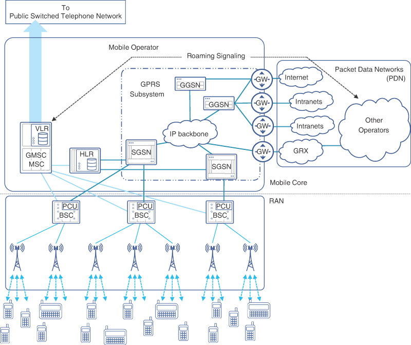
FIGURE 1-8 2.5G with GPRS Mobile Network Architecture
As Figure 1-8 illustrates, the collection of new entities introduced in the mobile core network by GPRS was called the GPRS Subsystem, or GSS. The key element of the GSS is the pair of Serving GPRS Support Node (SGSN) and Gateway GPRS Support Node (GGSN). Collectively, these two nodes bring mechanisms and protocols required to enable efficient packet-switched-based data transmission. The SGSN was the subscriber-facing node, while the GGSN interfaced with the PDN to complete the data connectivity for the subscriber. The functions of these nodes will be discussed in detail in the next chapter.
As seen in the figure, BSCs were also retrofitted with additional capability implemented by a Packet Control Unit (PCU) to identify and redirect data traffic toward the GSS, whereas the voice traffic continued to be sent to the MSC. The GGSN could forward subscriber traffic to the public Internet, various different intranets, or another mobile provider through a GPRS roaming exchange (GRX). The role of a GRX was critical in implementing 2G roaming across multiple mobile providers. Chapter 2 covers GRX extensively.
Enhanced Data Rates for GSM Evolution (EDGE)
With the growing need for data transmission over mobile networks, the GRPS subsystem continued to evolve. Without a major system redesign, new modulation and link adaptation methods were introduced that increased the efficiency of frequency use and timeslots utilization for packets. The changes, introduced to the market as EDGE (Enhanced Data Rates for GSM Evolution), were limited to the radio access network. Optimization in modulation and encoding provided a slightly higher data speed. As a result, EDGE offered a maximum data transmission speed of 384Kbps with all eight TDMA slots concatenated.7 EDGE was first deployed in the early 2000s, shortly after the introduction of GRPS.
Third Generation (3G)
Although EDGE, also sometimes referred to as 2.75G, did bring some improvements in data transmission speeds, it still could not keep up with the growing demands for data consumption. The industry forerunners envisioned rapid growth in both the subscriber base as well as the data volume pushed through the mobile network. The mainstream vision at that time pictured many additional services the next generation network would provide along with voice and data transmission, such as video telephony, digital video and audio delivery, advanced car navigation, collaborative applications, and others.8 Some of these services did gain momentum, while others had to wait until later generations of mobile networks.
At the same time, the proliferation of higher-speed Internet access with cable and DSL lines boosted adoption of applications offering voice and video calls, such as Skype and others. In many cases, the quality of voice over Internet using broadband exceeded the voice quality that mobile networks offered natively, thus putting competitive pressure on mobile network operators to improve call quality.
A new generation of mobile systems was needed to address these gaps. In the late 1990s, a few major mobile vendors and operators in North America started work on defining third generation mobile network principles. Many other mobile vendors and operators from around the world joined this initiative. This consortium, later called 3rd Generation Partnership Project (3GPP), released the first 3G mobile network specification called Release 99 in the year 2000. Release 99 defined the Universal Mobile Telecommunications System (UMTS) that forms the basis of 3G networks.
3GPP Standardization Efforts
3GPP, or 3rd Generation Partnership Project, is currently the de facto standardization body for the mobile industry. Although named after third generation, its standardization efforts extend into the fourth and fifth generations of mobile networks. 3GPP is a consortium uniting a number of national and regional standard development organizations. Major telecom vendors, wireless service providers, and national standard developing bodies contribute to the development of new mobile system architectures under the 3GPP umbrella. The three Technical Specification Groups (TSGs)—Radio Access Networks (RAN), Services and Systems Aspects (SA), and Core Network and Terminals (CT)—within 3GPP are further subdivided into Working Groups (WGs). All TSGs and WGs work together to create technical specifications called “releases,” with Release 99 being the first one.
The UMTS consisted of two key components: UMTS Terrestrial Radio Access Network (UTRAN) and UMTS Core Network (CN). The CN components and flows defined in Release 99 were very similar to GSM/GPRS network but evolved significantly over the next few 3GPP releases. In contrast, the UTRAN specification introduced many technological advances from the very beginning.
3G Innovations in Radio Access
The frequency resource was still a significant constraint in meeting the growing bandwidth demand. In addition to adding more frequency bands, 3G also offered more efficient air interface sharing among a growing number of subscribers and services.
Improvements in digital signal processing made it possible to consider more complex media access technologies than Frequency Division Multiple Access (FDMA) and Time Division Multiple Access (TDMA). This resulted in the acceptance of Wideband Code Division Multiple Access (WCDMA) as a standard for 3G. WCDMA is a flavor of CDMA that was used in some mobile networks of second generation, such a IS-95. WCDMA and CDMA are both multi-access technologies based on the same principle of separating user transmissions using codes. Compared to CDMA, WCDMA uses higher code rates, wider channel widths of 5MHz instead of 1.25MHz, and some other differences.
Unlike previous generation radio access, WCDMA does not assign a separate frequency or a timeslot to different users. Instead, their signals are transmitted at the same time and using the same frequency. This media access technology is based on a counterintuitive approach of transmitting a signal using substantially more bandwidth than would be necessary with other modulation techniques. Each bit or group of bits (a symbol) of an original digital signal is encoded by a few rectangular pulses (called “chips”), based on a special sequence of bits, called a “spreading code.” When an original digital signal is multiplied by such a code, it could be said that the signal is being spread over the spectrum, as a higher rate signal of rectangular pulses occupies a wider frequency spectrum compared to a similar but lower rate signal. The spectrum of an original signal becomes wider, and the energy of the original symbols is also distributed over the wider frequency band. Figure 1-9 illustrates the use of spreading codes over a digital signal in WCDMA.
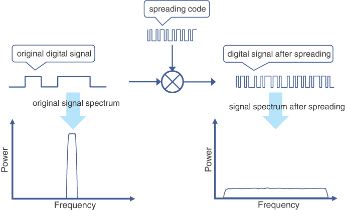
FIGURE 1-9 Digital Signal Modulation Using Spreading Codes
The reverse operation, or de-spreading, requires exactly the same code to recover the original signal. The energy of each original symbol is combined during de-spreading operations and results in the recovery of the symbol. This process is also referred to as “correlation.”
Spreading codes are generated in such a way that they maintain a mathematical property of orthogonality. When a de-spreading operation is done with a code different from the one used for spreading, it results in recovery of nearly zero energy for each symbol that appears as negligible noise. Different spreading codes are used to encode different data channels, making it possible to distinguish them at the receiver. Therefore, these are also referred to as “channelization codes.”
When both transmitter and receiver use the same code, the de-spreading operation recovers the original signal while effectively filtering out any other signals. This allows simultaneous transmission of multiple signals encoded with different orthogonal spreading codes using the same frequency band. Figure 1-10 illustrates the signal transmission and de-spreading operation in WCDMA.
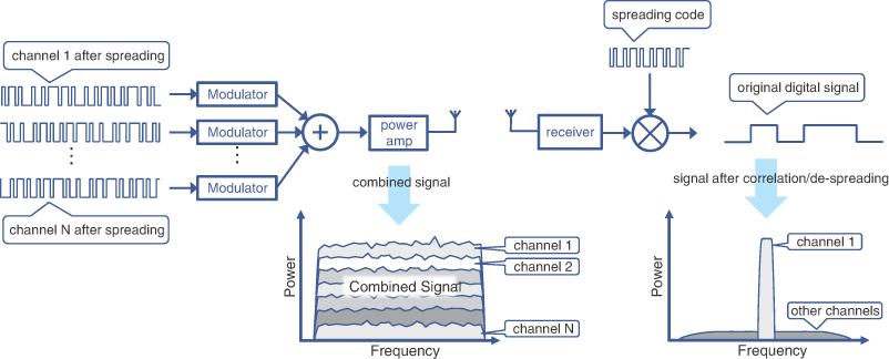
FIGURE 1-10 Multiple Signals Transmission and De-spreading Operation
The spreading codes used in WCDMA have a fixed rate of 3.84M chips per second, which is related to the width of a radio channel (5MHz). The number of chips used to encode a single bit (or more strictly, a symbol) of the original signal is known as “spreading factor” and may vary in WCDMA transmissions between 4 and 512.
When spreading codes don’t start at the same time, they might have decreased orthogonality. This becomes a challenge in WCDMA due to asynchronous mode of base stations operation. To cope with that, WCDMA uses an additional code, called a “scrambling code.” An already spread signal is further encoded by a scrambling code without increasing the rate of the signal. This operation ensures better orthogonality and helps to better distinguish transmissions from different mobile devices and base stations. Different scrambling codes are used by each individual transmitter in a cell.
WCDMA transmissions use Quadrature Phase-Shift Keying (QPSK) modulation in the downlinks and dual-channel QPSK in the uplinks. Without going into the complexity of modulation theory, suffice to say that QPSK modulation converts 2-bit symbols into a radio signal with four distinguishable phase shifts. Thus, each 2 bits of a downlink channel in UMTS are modulated by a single-phase shift of QPSK. In the uplink direction, however, 2 bits comprising a single symbol for QPSK are provided by two separate channels: control and data, hence the name dual-channel QPSK. Multiplexing of two uplink channels into a single transmission improves air interface efficiency when significant asymmetry of the traffic patterns exists between uplink and downlink.
Microdiversity and Macrodiversity in 3G
Use of expanded signal bandwidth in WCDMA has another benefit for UTRAN. The signal fading due to interfering multiple propagation paths can be compensated with so-called rake receivers. A typical rake receiver can be viewed as a collection of many radio receiver sub-units (fingers), which apply different delays to the signal and process it independently. The results are then combined, harvesting more of the signal’s energy that’s otherwise wasted. This concept is also known as microdiversity combining. UMTS introduced the use of rake receivers in both base stations and mobile devices.
Along with microdiversity combining, UMTS also employs macrodiversity combining, where a signal received by two adjacent cells is compared and combined at the Radio Network Controller (RNC). When a signal from an adjacent cell becomes substantially better, the mobile device might experience soft handover to an adjacent cell if it is controlled by the same RNC. Soft handovers reduce the amount of signaling required in UTRAN and prevent gaps in communication resulting from this.
When adjacent cells participating in macrodiversity are controlled by different RNCs, UTRAN defines a special interface for RNC-to-RNC communication.
The very foundational principle of WCDMA, that all mobile devices within the cell transmit on the same radio frequency, can lead to a situation where a single powerful transmission jams all other (weaker) signals. This is also known as “near-far problem” in CDMA systems. To address this problem, it is critical to control power of each mobile device transmitting in the cell. Each radio node constantly evaluates radio signal parameters, such as signal-to-interference ratio (SIR), and instructs each device to reduce or increase its power level.
In addition to these, there were many other innovations such as Adaptive Multi-Rate (AMR) codecs for voice, switching off transmissions during voice silence or gaps in data streams with discontinuous transmissions (DTX), and so on, but their details fall outside the scope of this book. Collectively, these innovations helped to create a robust, efficient, and fast UMTS air interface, reaching the peak speeds of 2Mbps in the downlink and 768Kbps in the uplink; however, later 3GPP releases boosted achievable data rates significantly.
3G Mobile Transport
3G UMTS introduced the concept of NodeB, which terminates the air interface from mobile devices and is considered the demarcation point between radio access networks and the mobile backhaul network. Similar to its predecessor (BTS) in 2G, NodeB required connectivity to its controller in the mobile core. In 3G, the controller is called the Radio Network Controller (RNC), and NodeB relies on the mobile transport to provide robust connectivity between the two.
Initial 3G implementations used a similar approach for mobile transport as their predecessor (that is, point-to-point T1/E1 links between the NodeB and RNC). As bandwidth consumption continued to grow, however, the 1.5/2Mbps capacity offered by T1/E1 links quickly became saturated. The use of 5MHz channels, along with the efficient coding techniques, significantly increased the bandwidth requirements in the mobile backhaul (that is, from the cell site to the mobile core). One of the solutions was to use multiple T1/E1 links; another option was an upgrade to higher capacity T3/E3 links. This was a costly proposition, however, given the dedicated use of such point-to-point links, and the industry moved toward higher capacity yet cost-effective alternates such as Asynchronous Transfer Mode (ATM) and IP in the mobile backhaul.
Around the same time when the first 3G networks were being deployed, Internet providers and network operators were also deploying high-speed data networks to meet the growing Internet bandwidth requirements. One of the leading technologies for such networks was ATM, which provided higher speeds (155Mbps or more), traffic prioritization through quality of service (QoS), and predictable traffic delay. These properties made ATM a suitable transport mechanism for mobile traffic, where voice required careful handling due to its time-sensitive nature and data required higher bandwidth.
With 3GPP standardizing the use of ATM, and subsequently Internet Protocol (IP), for mobile transport, this presented service providers with an opportunity to consolidate their Internet and mobile transport networks. The potential to use a single transport network tempted the service providers and network operators to embrace a common technology for mobile and Internet transport in the hopes of optimizing operation, reducing operational expenses, and extracting maximum return on investment on their deployments. For mobile communication networks (MCNs), this meant that instead of using purpose-built, mostly point-to-point links, base stations and NodeBs could utilize general-purpose high-speed data networks to connect to the mobile core. While this concept of a “single converged network” was introduced in 3G, it did not see significant adoption in most service providers until well into the 2010s. Some service providers preferred to maintain separate physical networks for mobile and traditional data networks, while many others made substantial strides towards consolidating the two. 3G heralded the arrival of the mobile backhaul (MBH) era for MCNs. Whereas, previously, transport was simply a collection of dedicated point-to-point links from a base station to the mobile core, MBH networks provided a blueprint for robust, reliable, multiservice connectivity within and between the radio access network and the mobile core. MBH networks are discussed in more detail in the next chapter.
3G Mobile Core
As previously mentioned, the 3GPP definition of the core network in Release 99 did not feature many changes to the GSM/GPRS standards. Although new interfaces were defined to interact with UTRAN, the main constituents of the core network remained largely unchanged: MSC, GMSC, HLR, SGSN, GGSN, and so on. However, scalability challenges in the circuit switched domain became a reality due to mobile networks’ expansion and consolidation over large geographic areas. Major core network changes were therefore introduced in 3GPP Release 4 to address these challenges by splitting the functions of MSC into two entities: MSC server (MSC-S) and media gateway (MGW). Figure 1-11 shows an overview of the 3G/UMTS architecture and components.
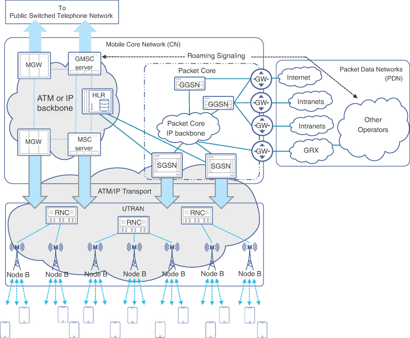
FIGURE 1-11 3G/UMTS Architecture at a Glance
The MSC-S is sometimes also referred to as a “call server” and implements call control and signaling. Put simply, MSC-S takes care of call routing decisions and negotiating voice bearer requirements when a mobile subscriber makes or receives a circuit switched voice call. MSC-S is also responsible for HLR interrogation, maintaining VLR, and the generation of call detail records for the billing system. An MSC-S connecting its mobile networks with other networks is called Gateway MSC-S (GMSC-S).
While MSC-S and GMSC-S implement call control and signaling, the actual circuit switching is performed by media gateways (MGWs). In other words, MGWs provide bearers for circuit switched voice, perform media conversion between TDM and ATM or IP-based voice, transcoding, and other call-related functions such as echo cancellation.
Both ATM and IP were defined by 3GPP as acceptable transport for MGW and MSC connectivity. The signaling between MSC-S, which was originally done using a protocol called Signaling System 7 (SS7), can now be carried over ATM or IP. When carried over IP, it is referred to as SIGTRAN, short for signaling transport.
Although some significant changes were introduced in the circuit switched part of 3G CN, the packet switched domain remained largely unchanged. The functional split between SGSN and GGSN allowed for scaling the packet switched domain efficiently by adding more SGSNs and/or GGSNs where and when needed. SGSNs and GGSNs were retrofitted with new interfaces to communicate with RNCs in the UTRAN over ATM or IP.
The terms circuit switched core and packet switched core also emerged to distinguish between two major functional domains of 3G CN, with the latter further simplified to just packet core. Even though the circuit switched core could now use an ATM or IP backbone for connectivity, interestingly enough it remained separate from the packet-switched core’s IP backbone in most implementations.
3G Enhancements
Though 3GPP had originally defined its Release 99 for the third generation mobile wireless specifications, the consortium continued to define new specifications in the subsequent years. Unlike Release 99, where the number “99” was influenced by the year (1999) when most of it was developed, the subsequent releases were simply given a sequential name, starting with Release 4.
These released specifications had varying degrees of influence on the RAN, transport, and mobile core of 3G mobile systems. These influences will be discussed in this section.
3GPP Release 4
As mentioned in the previous section, Release 4 brought a major change to the packet core with a very significant step of specifying the MGW and MSC-S. The use of the IP network to communicate between these was the first step toward the transition away from circuit switched voice.
While 3G networks based on Release 99 were mostly limited to proof of concepts, lab trials, and few early deployments, the 3GPP Release 4 was the first release of 3G specifications that was practically deployed. Release 99 standards, however, were widely used in production deployment as part of 2G, 2.5G, and EDGE networks.
3GPP Release 5
Release 5 of 3GPP was more focused toward defining new radio specifications to improve bandwidth. For this reason, Release 5 and its subsequent releases are collectively referred to as High Speed Packet Access (HSPA).
In Release 5, the downlink speed (cell tower to mobile user) was the focus, hence it’s called High Speed Downlink Packet Access (HSDPA). The specifications made it possible for the theoretical maximum speed to be increased to 14.4Mbps, through the use of a new modulation technique. It was a big increase compared to the previous theoretical maximum of Release 99.
On the mobile core, Release 5 specified the IP Multimedia Subsystem (IMS) with the goal of moving to packet switched voice communication; however, IMS didn’t see any real traction until much later. IMS will therefore be discussed in more detail in Chapter 3, “Mobile Networks Today.”
3GPP Release 6
As Release 5 had enhanced downlink speeds, Release 6 (which is also part of HSPA) provided specifications to enhance uplink speeds and hence was known as High Speed Uplink Packet Access (HSUPA). HSUPA bumped up uplink speeds to 5.8Mbps under ideal radio conditions.
3GPP Release 7
The predominant change that Release 7 of the 3GPP specifications brought was once more focused on improving the data speeds over the air interface. Using more sophisticated modulation techniques and multiple simultaneous transmissions, the theoretical downlink speed was increased to 28Mbps, while the uplink speeds were brought up to 11Mbps. These speeds still required ideal conditions, and the realistically achievable speeds were somewhat lower. Regardless, these speeds offered a great amount of improvement compared to 2G speeds. To distinguish these changes from HSPA, the Release 7 data rate enhancements are referred to as HSPA+.
Release 7 also brought some improvements to the connectivity mechanism used by the mobile devices. Previously, devices experienced excessive battery drain in the idle state before they went into sleep mode. When waking up from the sleep state, they faced a significant lag in connectivity. New specifications in Release 7 brought major improvements in this area and thus improved the battery power consumption for devices. The details of these techniques, known as Continuous Packet Connectivity (CPC), are beyond the scope of this book.
3GPP Release 8 and Beyond
After 3GPP Release 4, which had brought significant changes to the mobile core, all the releases were more focused on improving the air interface data rates. However, Release 8 once again specified major changes to the mobile core using the new specifications called Evolved Packet Core (EPC). On the radio side, it specified Enhanced Universal Terrestrial Radio Access Network (E-UTRAN).
These enhancements, known as Long-Term Evolution (LTE), paved the path for 4G networks, which are covered in Chapter 3.
Figure 1-12 shows a progression of uplink and downlink speeds across various 3GPP releases.
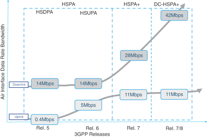
FIGURE 1-12 3GPP Releases and Corresponding Theoretical Speeds
3G Technology Summary
2G passed the baton to the third generation of mobile networks at a critical turning point in mobile networking history.
3G enhanced mobile services on two major fronts. Early 3GPP releases focused on major changes in the radio access technologies with the use of WCDMA, establishing a solid foundation for air interface evolution. Through the separation of MSC functions into MSC-S and MGW, 3G kickstarted the adoption of ATM/IP transport in the mobile core and eventually in the mobile transport. The transition from TDM to ATM/IP promised operational expense reduction and maximization of the return on investment on future deployments.
Later 3GPP releases introducing HSPA provided tangible benefits to end users through higher upload and download speeds. The result was a massive growth in the subscriber base. By the end of 2008, the number of mobile subscriptions surpassed 4 billion globally.9
Summary
This chapter covered the evolution of mobile services from pre-cellular mobile networks through the third generation. Many key concepts were covered, including the following:
The three domains of mobile communication networks: radio access network, mobile transport, and mobile core
Building blocks of each of these domains across multiple generations
The concept of a cell and frequency spectrum reuse
The limitations of each mobile generation and the solution adopted to overcome those in the next generation
Industry adoption for every generation of mobile communication
Knowledge of these topics and their historical context play a key role in understanding the principles of mobile communication. The next chapter will explore the three distinct domains of the mobile communication network in more detail and will discuss how these domains interact together to provide end-to-end services.
References
1. https://www.britannica.com/technology/mobile-telephone#ref1079045 (last visited: Mar 2022)
2. Theodore S. Rappaport, Wireless Communications: Principles and Practice, 2nd Edition (Upper Saddle River, N.J.: Prentice Hall PTR, 2002), Chapter 1.
3. Op. cit., Chapters 2 and 11.
5. https://www.qualcomm.com/news/releases/1998/09/02/qualcomm-awarded-first-cdmaone-technology-type-approval-and-quality (last visited: Mar 2022)
6. https://www.itu.int/itunews/issue/2003/06/thirdgeneration.html
7. https://www.3gpp.org/technologies/keywords-acronyms/102-gprs-edge
8. http://www.itu.int/osg/spu/ni/3G/workshop/Briefing_paper.doc