Chapter 3. Troubleshooting RIP
This chapter covers the following key topics:
• Troubleshooting RIP routes installation
• Troubleshooting RIP routes advertisement
• Troubleshooting routes summarization in RIP
• Troubleshooting RIP redistribution problems
• Troubleshooting dial-on-demand (DDR) routing issues in RIP
• Troubleshooting route flapping problem in RIP
This chapter discusses some of the common problems in RIP and tells how to resolve those problems. At this time, no RIP error messages will help troubleshooting RIP problems. As a result, you will need to rely on debugs, configurations, and useful show commands, which we’ll provide where necessary in this chapter. The flowcharts that follow document how to address common problems with RIP with the methodology used in this chapter.
Debugs sometimes can be very CPU-intensive and can cause congestion on your network. Therefore, we do not recommend turning on these debugs if you have a large network (that is, more than 100 networks or subnets in RIP). Sometimes, there could be multiple causes for the same problem—for example, Layer 2 is down, the network statement is wrong, and the sender is missing the network statement. Bringing up Layer 2 and fixing the network statement might not fix the network problem because the sender is still missing the network statement. Therefore, if one scenario doesn’t fix the network problem, check into other scenarios. The word RIP, in general, refers to both RIP Version 1 (RIP-1) and RIP Version 2 (RIP-2). The problems discussed in this chapter are mostly related to RIP-1, unless specified as RIP-2.
Flowcharts to Solve Common RIP Problems


Troubleshooting RIP Routes Installation
This section discusses several possible scenarios that can prevent RIP routes from getting installed in the routing table. This section is selected first in the troubleshooting list because the most common problem in RIP is that routes are not installed in the routing table.
If the routes are not installed in the routing table, the router will not forward the packets to destinations that are not in the routing table. When this happens, it creates reachability problems. Users start complaining that they cannot reach a server or a printer. When you investigate this problem, the first thing to ask is, “Do I have a route for this destination that users are complaining about?”
Three possibilities exist for routes not getting installed in the routing table:
• Receiver’s problem—The router is receiving RIP updates but is not installing the RIP routes.
• Intermediate media problem (Layer 2)—Mostly related to Layer 2, the sender has sent the RIP updates, but they got lost in the middle and the receiver didn’t receive them.
• Sender’s problem—The sender is not even advertising RIP routes, so the receiving side is not seeing any RIP routes in the routing table.
The sender’s problem will be discussed in the section “Troubleshooting RIP Route Advertisement.” Two problems are related to RIP installation:
• RIP routes are not in the routing table.
• RIP is not installing all equal-cost path routes.
In the first problem, RIP is not installing any path to a specific network. In the second problem, RIP is not installing all paths to the network. Note that, in the second problem, the destination device is still reachable, but it’s not listing all possible paths.
Problem: RIP Routes Not in the Routing Table
The routing table must have a network entry to send the packets to the desired destination. If there is no entry for the specific destination, the router will discard all the packets for this destination.
Example 3-1 shows that the routing table of R2 doesn’t hold an entry for network 131.108.2.0.
Example 3-1 Routing Table for R2 Shows No RIP Routes for Subnet 131.108.2.0
R2#show ip route 131.108.2.0
% Subnet not in table
R2#
The possible causes for this problem are as follows:
• Missing or incorrect network statement
• Layer 2 down
• Distribute list blocking the route
• Access list blocking RIP source address
• Access list blocking RIP broadcast/multicast
• Incompatible version type
• Mismatch authentication key (RIP-2)
• Discontiguous network
• Invalid source
• Layer 2 problem (switch, Frame Relay, other Layer 2 media)
• Offset list with a large metric defined
• Routes that reached RIP hop-count limit
• Sender problem (discussed in the next chapter)
Figure 3-1 provides a network scenario that will be used as the basis for troubleshooting a majority of the aforementioned causes of the problem of RIP routes not in the routing table. The sections that follow carefully dissect how to troubleshoot this problem based on specific causes.

Figure 3-1 Example Topology for the Problem of RIP Routes Not in the Routing Table
Figure 3-1 shows a setup in which Router 1 and Router 2 are running RIP between them.
RIP Routes Not in the Routing Table—Cause: Missing or Incorrect network Statement
When you confirm that the route is missing from the routing table, the next step is to find out why. A route can be missing from the routing table for many reasons. The flowcharts at the beginning of this chapter can help isolate the cause that seems to fit most in your situation.
The obvious thing to check after discovering that the routes are not in the routing table is the router’s configurations. Also check to see whether the network statement under router rip is properly configured.
When the network statement is configured, it does two things:
• Enables RIP on the interface and activates the capability to send and receive RIP updates
• Advertises that network in a RIP update packet
If the network statement under router rip command is not configured or misconfigured, it can cause this problem.
Figure 3-2 shows the flowchart to follow to solve this problem based on this cause.

Figure 3-2 Problem Resolution Flowchart
Debugs and Verification
Example 3-2 shows the configuration for Router R2 (as illustrated in Figure 3-1). The loopback interface is used in this example and many other examples throughout the chapter. If the loopback interface is replaced with any other interface, it will not change the meaning. We suggest that you treat the loopback as any interface that is up and functional and that has a valid IP address.
Example 3-2 Configuration for Router R2 from Figure 3-1
interface Loopback0
ip address 131.108.3.2 255.255.255.0
!
interface Ethernet0
ip address 131.108.1.2 255.255.255.0
!
router rip
network 131.107.0.0
!
Refer back to Figure 3-1 and compare it to the configuration for R2 in Example 3-2. You notice that network 131.108.0.0 is missing from R2’s configurations.
Example 3-3 shows the output of the show ip protocols command on R2. This output shows that the routing information source is also not displaying 131.108.1.1 as a gateway.
Example 3-3 show ip protocols Missing Gateway Information for Routing Information Source
R2#show ip protocols
Routing Protocol is "rip"
Sending updates every 30 seconds, next due in 11 seconds
Invalid after 180 seconds, hold down 180, flushed after 240
Outgoing update filter list for all interfaces is
Incoming update filter list for all interfaces is
Redistributing: rip
Default version control: send version 1, receive any version
Automatic network summarization is in effect
Routing for Networks:
131.107.0.0
Routing Information Sources:
Gateway Distance Last Update
Distance: (default is 120)
Debug Commands
Example 3-4 shows the debug ip rip output. In this debug, R2 is ignoring the RIP updates coming from R1 because RIP is not enabled on Ethernet 0. This is because of the lack of a network statement for 131.108.0.0 under router rip in the router configuration mode.
Example 3-4 debug ip rip Command Output Displays That RIP Updates from Router R1 Are Being Ignored
R2#debug ip rip
RIP protocol debugging is on
R2#
RIP: ignored v1 packet from 131.108.1.1 (not enabled on Ethernet0)
R2#
Solution
Because the network statement is missing on Router 2, as shown in Example 3-2, it ignores RIP updates arriving on its Ethernet 0 interface, as seen in the debug output in Example 3-4. This problem can also happen if incorrect network statements are configured. Take a Class C address, for example. Instead of configuring 209.1.1.0, you configure 209.1.0.0, assuming that 0 will cover anything in the third octet. RIP-1 is a classful protocol, and it assumes the classful network statements. If a cidr statement is configured instead, RIP will not function properly.
To correct this problem, you must add the network statement in the configurations.
Example 3-5 shows the new configuration for Router R2 that solves this problem.
Example 3-5 New Configuration of R2 That Solves the Problem
interface Loopback0
ip address 131.108.3.2 255.255.255.0
!
interface Ethernet0
ip address 131.108.1.2 255.255.255.0
!
router rip
network 131.107.0.0
network 131.108.0.0
Example 3-6 shows the output of show ip protocols on R2. This output displays the gateway information now.
Example 3-6 show ip protocols Showing Gateway Set to the R1’s Interface IP Address
R2#show ip protocols
Routing Protocol is "rip"
Sending updates every 30 seconds, next due in 12 seconds
Invalid after 180 seconds, hold down 180, flushed after 240
Outgoing update filter list for all interfaces is
Incoming update filter list for all interfaces is
Redistributing: rip
Default version control: send version 1, receive any version
Interface Send Recv Triggered RIP Key-chain
Ethernet0 1 1 2
Loopback0 1 1 2
Automatic network summarization is in effect
Routing for Networks:
131.108.0.0
Routing Information Sources:
Gateway Distance Last Update
131.108.1.1 120 00:00:09
Distance: (default is 120)
Example 3-7 shows the output of show ip route, which shows that Router R2 is learning the RIP route after the configuration change.
Example 3-7 show ip route Displays the Route Being Learned After Fixing the Problem
R2#show ip route 131.108.2.0
Routing entry for 131.108.2.0/24
Known via "rip", distance 120, metric 1
Redistributing via rip
Last update from 131.108.1.1 on Ethernet0, 00:00:11 ago
Routing Descriptor Blocks:
* 131.108.1.1, from 131.108.1.1, 00:00:11 ago, via Ethernet0
Route metric is 1, traffic share count is 1
RIP Routes Not in the Routing Table—Cause: Layer 1/2 Is Down
One cause for routes not in the routing table is Layers 1 or 2 being down. If Layers 1 or 2 are down, it’s not a RIP problem. The following is a list of the most common things to check if the interface or line protocol is down:
• Unplugged cable
• Loose cable
• Bad transceiver
• Bad port
• Bad interface card
• Layer 2 problem at telco, in case of a WAN link
• Missing clock statement, in case of back-to-back serial connection
Figure 3-3 shows the flowchart to follow to solve this problem based on this cause.

Figure 3-3 Flowchart to Solve Why RIP Routes Don’t Show Up in a Routing Table
Debugs and Verification
Example 3-8 shows that the Ethernet interface’s line protocol is down, indicating that something is wrong at Layer 1 or Layer 2.
Example 3-8 show interface output Displays That the Line Protocol Is Down
R2#show interface ethernet 0
Ethernet0 is up, line protocol is down
Hardware is Lance, address is 0000.0c70.d41e (bia 0000.0c70.d41e)
Internet address is 131.108.1.2/24
Debugs
Example 3-9 shows the output of debug ip rip. In this debug, R2 is not sending or receiving any RIP updates because Layer 2 is down.
Example 3-9 debug ip rip Command Output Shows Nothing Is Being Sent
R2#debug ip rip
RIP protocol debugging is on
R2#
Solution
RIP runs above Layer 2. RIP cannot send or receive any routes if Layer 2 is down.
The Layer 2 problem must be fixed. Sometimes, the problem could be as simple as loose cables, or it could be as complex as bad hardware; in which case, the hardware must be replaced.
Example 3-10 shows the output of show interface Ethernet 0 on R2 after the Layer 2 problem is fixed. The output shows that the line protocol is now up.
Example 3-10 show interface Output After Fixing the Layer 1/2 Problem Shows the Interface Ethernet0 Is Now Up
R2#show interface Ethernet0
Ethernet0 is up, line protocol is up
Hardware is Lance, address is 0000.0c70.d41e (bia 0000.0c70.d41e)
Internet address is 131.108.1.2/24
Example 3-11 shows the output of show ip route, which illustrates that the RIP route is being learned after fixing the Layer 1/2 problem.
Example 3-11 Routing Table Entry After Fixing the Layer 1/2 Problem
R2#show ip route 131.108.2.0
Routing entry for 131.108.2.0/24
Known via "rip", distance 120, metric 1
Redistributing via rip
Last update from 131.108.1.1 on Ethernet0, 00:00:07 ago
Routing Descriptor Blocks:
* 131.108.1.1, from 131.108.1.1, 00:00:07 ago, via Ethernet0
Route metric is 1, traffic share count is 1
RIP Routes Not in the Routing Table—Cause: distribute-list in Is Blocking the Route
A distribute list is a filtering mechanism for routing updates. The distribute list calls an access list and checks to see which networks are supposed to be permitted. If the access list doesn’t contain any network, the routing update will be automatically denied. A distribute list can be applied on either incoming routing updates or outgoing routing updates.
In this example, the distribute-list in is configured; however, the access list doesn’t contain the permit statement for 131.108.0.0, so R2 is not installing these routes in the routing table.
Figure 3-4 shows the flowchart to follow to solve this problem based on this cause.

Figure 3-4 Flowchart to Solve Why RIP Routes Don’t Show Up in a Routing Table
Debugs and Verification
Example 3-12 shows the current configuration of Router R2. In this configuration, access-list 1 is used to permit network 131.107.0.0; however, there is an implicit deny at the end of every access list, so 131.108.0.0 will also be denied. In the access list configuration, network 131.108.0.0 is not permitted, so the router is not installing any subnets of the 131.108.0.0 network.
Example 3-12 R2’s Configuration Shows That Network 131.108.0.0 Is Being Blocked with an Implicit deny Under access-list 1
interface Loopback0
ip address 131.108.3.2 255.255.255.0
!
interface Ethernet0
ip address 131.108.1.2 255.255.255.0
!
router rip
network 131.108.0.0
distribute-list 1 in
!
access-list 1 permit 131.107.0.0 0.0.255.255
Solution
When a distribute list is used, you should always double-check your access list to make sure that the networks that are supposed to be permitted actually are permitted in the access list. The access list in Example 3-12 permits only 131.107.0.0 and denies everything else because there is an implicit deny at the end of each access list. To fix this problem, permit 131.108.0.0 in access-list 1.
Example 3-13 shows the new configuration of Router R2 with the access list to permit 131.108.0.0.
Example 3-13 Correcting the Configuration on R2 to Fix the Problem
interface Loopback0
ip address 131.108.3.2 255.255.255.0
!
interface Ethernet0
ip address 131.108.1.2 255.255.255.0
!
router rip
network 131.108.0.0
distribute-list 1 in
!
access-list 1 permit 131.107.0.0 0.0.255.255
access-list 1 permit 131.108.0.0 0.0.255.255
Example 3-14 shows that Router R2 is learning RIP routes after the configuration change.
Example 3-14 R2 Routing Table Is Learning the RIP Routes After the Correction
R2#show ip route 131.108.2.0
Routing entry for 131.108.2.0/24
Known via "rip", distance 120, metric 1
Redistributing via rip
Last update from 131.108.1.1 on Ethernet0, 00:00:07 ago
Routing Descriptor Blocks:
* 131.108.1.1, from 131.108.1.1, 00:00:07 ago, via Ethernet0
Route metric is 1, traffic share count is 1
RIP Routes Not in the Routing Table—Cause: Access List Blocking RIP Source Address
Access lists are used to filter the traffic based on the source address. Extended access lists are used to filter the traffic based on the source or destination address, T-2. To filter the incoming and outgoing traffic, these access lists may be applied on the interface with this interface-level command:
ip access-group access-list number {in | out}
When the access list is applied in a RIP environment, always make sure that it doesn’t block the source address of the RIP update. In this example, R2 is not installing RIP routes in the routing table because access-list 1 is not permitting the source address of RIP updates from R1.
Figure 3-5 shows the flowchart to follow to solve the problem based on this cause.

Figure 3-5 Flowchart to Solve Why RIP Routes Don’t Show Up in a Routing Table
Debugs and Verification
Example 3-15 shows the current configuration of router R2. The access list in R2 is not permitting the source address of RIP updates, that is, 131.108.1.1. In Figure 3-1, 131.108.1.1 is the source address of R1 RIP updates. Because there is an implicit deny at the end of each access list, 131.108.1.1 will be automatically denied.
Example 3-15 access-list 1 Is Not Permitting the Source Address
R2#
interface Loopback0
ip address 131.108.3.2 255.255.255.0
!
interface Ethernet0
ip address 131.108.1.2 255.255.255.0
ip access-group 1 in
!
router rip
network 131.108.0.0
!
access-list 1 permit 131.107.0.0 0.0.255.255
Debugs
The output of debug ip rip in Example 3-16 shows that RIP is only sending the updates, not receiving anything, because the source address 131.108.1.1 is not permitted in the input access list of R2.
Example 3-16 debug ip rip Output Reveals That R2 Is Not Receiving Any RIP Updates
R2#debug ip rip
RIP: sending v1 update to 255.255.255.255 via Ethernet0 (131.108.1.2)
RIP: build update entries
subnet 131.108.3.0 metric 1
RIP: sending v1 update to 255.255.255.255 via Loopback0 (131.108.3.1)
RIP: build update entries
subnet 131.108.1.0 metric 1RIP: sending v1 update to 255.255.255.255 via
Ethernet0 (131.108.1.2)
RIP: build update entries
subnet 131.108.3.0 metric 1
RIP: sending v1 update to 255.255.255.255 via Loopback0 (131.108.3.1)
RIP: build update entries
subnet 131.108.1.0 metric 1
R2#
Solution
The standard access list specifies the source address. In this case, the source address is 131.108.1.1, which is the sending interface address of R1. This source address is not permitted in the standard access list of R2, so RIP routes will not get installed in the routing table of R2. To solve this problem, permit the source address in access list 1.
Example 3-17 shows the new configuration change to fix this problem.
Example 3-17 The Modified Access List Permits the Source Address
R2#
interface Loopback0
ip address 131.108.3.2 255.255.255.0
!
interface Ethernet0
ip address 131.108.1.2 255.255.255.0
ip access-group 1 in
!
router rip
network 131.108.0.0
!
access-list 1 permit 131.107.0.0 0.0.255.255
access-list 1 permit 131.108.1.1 0.0.0.0
This problem can also happen when using extended access lists if the RIP source address is not permitted in the access list. This solution also can be used in the case of an extended access list. The idea here is to permit the source address of RIP update.
Example 3-18 shows the configuration with an extended access list.
Example 3-18 The Correct Extended Access List Configuration, if Used
R2#
interface Loopback0
ip address 131.108.3.2 255.255.255.0
!
interface Ethernet0
ip address 131.108.1.2 255.255.255.0
ip access-group 100 in
!
router rip
network 131.108.0.0
!
access-list 100 permit ip 131.107.0.0 0.0.255.255 any
access-list 100 permit ip host 131.108.1.1 any
Example 3-19 shows the routing table of Router R2, which shows that it has learning RIP routes after the configuration change.
Example 3-19 R2 Is Receiving RIP Routes After Fixing the Access List Configuration
R2#show ip route 131.108.2.0
Routing entry for 131.108.2.0/24
Known via "rip", distance 120, metric 1
Redistributing via rip
Last update from 131.108.1.1 on Ethernet0, 00:00:07 ago
Routing Descriptor Blocks:
* 131.108.1.1, from 131.108.1.1, 00:00:07 ago, via Ethernet0
Route metric is 1, traffic share count is 1
RIP Routes Not in the Routing Table—Cause: Access List Blocking RIP Broadcast or Multicast (in Case of RIP-2)
Access lists are used to filter certain types of packets. When using access lists on the interface inbound, always make sure that they are not blocking the RIP broadcast or UDP port 520, which is used by RIP-1 and RIP-2 (or the RIP multicast address, in cases of RIP-2).
If these addresses are not permitted in the access list that is applied on the interface inbound, RIP will not install any routes in the routing table learned on that interface.
Figure 3-6 shows the flowchart to follow to solve this problem based on this cause.

Figure 3-6 Flowchart to Solve Why RIP Routes Don’t Show Up in a Routing Table
Debugs and Verification
Example 3-20 shows the current configuration of R2. In this configuration, RIP’s destination address of 255.255.255.255 is not being permitted. This will result in no RIP routes being installed in R2’s routing table. The RIP updates sent from R1 to the destination of 255.255.255.255 will be blocked by R2.
Example 3-20 R2 Configuration Does Not Permit RIP-1 Broadcast Addresses
R2#
interface Loopback0
ip address 131.108.3.2 255.255.255.0
!
interface Ethernet0
ip address 131.108.1.2 255.255.255.0
ip access-group 100 in
!
router rip
network 131.108.0.0
!
access-list 100 permit ip 131.107.0.0 0.0.255.255 any
access-list 100 permit ip host 131.108.1.1 host 131.108.1.2
Solution
RIP-1 broadcasts its routing updates on 255.255.255.255. This address must be permitted in the input access list of the receiving router so that it can receive the RIP updates.
Example 3-21 shows the new configuration for Router R2. access-list 100 is modified so that it can permit the RIP broadcast address that was being blocked before.
Example 3-21 Configuring Router R2’s Input Access List to Accept RIP-1 Broadcasts
interface Loopback0
ip address 131.108.3.2 255.255.255.0
!
interface Ethernet0
ip address 131.108.1.2 255.255.255.0
ip access-group 100 in
!
router rip
network 131.108.0.0
!
access-list 100 permit ip 131.107.0.0 0.0.255.255 any
access-list 100 permit ip host 131.108.1.1 host 131.108.1.2
access-list 100 permit ip host 131.108.1.1 host 255.255.255.255
In cases of RIP-2, the configuration will change slightly. The multicast address needs to be permitted instead of the broadcast address, as shown in Example 3-22.
Example 3-22 Configuring Router R2’s Input Access List to Accept RIP-2 Multicast
interface Loopback0
ip address 131.108.3.2 255.255.255.0
!
interface Ethernet0
ip address 131.108.1.2 255.255.255.0
ip access-group 100 in
!
router rip
version 2
network 131.108.0.0
!
access-list 100 permit ip 131.107.0.0 0.0.255.255 any
access-list 100 permit ip host 131.108.1.1 host 131.108.1.2
access-list 100 permit ip host 131.108.1.1 host 224.0.0.9
Example 3-23 shows the routing table of R2 after correcting the problem.
Example 3-23 R2 Routing Table After Correcting the Access List Shows That the RIP Routes Are Being Learned
R2#show ip route 131.108.2.0
Routing entry for 131.108.2.0/24
Known via "rip", distance 120, metric 1
Redistributing via rip
Last update from 131.108.1.1 on Ethernet0, 00:00:07 ago
Routing Descriptor Blocks:
* 131.108.1.1, from 131.108.1.1, 00:00:07 ago, via Ethernet0
Route metric is 1, traffic share count is 1
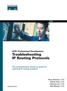
RIP Routes Not in the Routing Table—Cause: Incompatible RIP Version Type
When RIP is configured on a router, it is run by default as Version 1, which means that all its interfaces will send and receive RIP-1 packets only. To run Version 2 of RIP, you must add the version 2 line under router rip. When a router running Version 1 receives a RIP update from a router running Version 2, it ignores the updates and does not install any routes in the routing table. For a router to accept a Version 2 packet, the interface must be configured to accept the RIP-2 updates.
Figure 3-7 shows the flowchart to follow to solve this problem based on this cause.
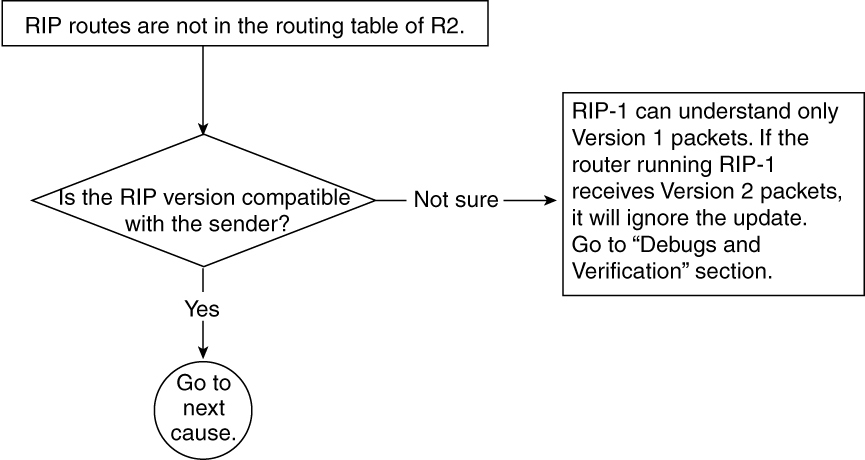
Figure 3-7 Flowchart to Solve Why RIP Routes Don’t Show Up in a Routing Table
Debugs and Verification
Example 3-24 shows the configuration of Router R2. In this configuration, RIP is configured to send and receive Version 1 packets only.
Example 3-24 R2 Configuration Shows That It Is Configured for RIP-1, Which Is the Default
R2#
interface Loopback0
ip address 131.108.3.2 255.255.255.0
!
interface Ethernet0
ip address 131.108.1.2 255.255.255.0
!
router rip
network 131.108.0.0
!
Example 3-25 shows the output of the debug ip rip command. This command reveals that R2 is receiving a RIP packet from R1, which is configured to send Version 2 updates.
Example 3-25 debug ip rip Command Output Shows the Version Incompatible Message on R2
R2#debug ip rip
RIP protocol debugging is on
RIP: ignored v2 packet from 131.108.1.1 (illegal version)
Example 3-26 shows the output of the show ip protocols command, which indicates that the Ethernet0 interface is sending and receiving RIP-1 packets. This means that if a Version 2 packet is received on Ethernet 0 of R2, it will be ignored because the interface can send and receive only Version 1 packets.
Example 3-26 show ip protocols Command Output Reveals the RIP Sends Out and Receives Only RIP Version 1 Packets on Ethernet0
R2#show ip protocols
Routing Protocol is "rip"
Sending updates every 30 seconds, next due in 9 seconds
Invalid after 180 seconds, hold down 180, flushed after 240
Outgoing update filter list for all interfaces is
Incoming update filter list for all interfaces is
Redistributing: rip
Default version control: send version 1, receive version 1
Interface Send Recv Key-chain
Ethernet0 1 1
Loopback0 1 1
Routing for Networks:
131.108.0.0
Routing Information Sources:
Gateway Distance Last Update
131.108.1.1 120 00:01:34
Distance: (default is 120)
R2#
Example 3-27 shows the configuration of R1. This shows that sender R1 is configured to send Version 2 packets. The command version 2 enables a router to send and accept only RIP-2 packets.
Example 3-27 R1’s Configuration Reveals That It Is Configured for RIP Version 2 Packets
R1#
router rip
version 2
network 131.108.0.0
Example 3-28 shows the output of the show ip protocols command, which shows that the sender R1 is sending and receiving only Version 2 packets. This is because of the version 2 command that is configured under router rip.
Example 3-28 show ip protocols Command Output Reveals That R1 Is Sending and Receiving Only RIP Version 2 Packets
R1#show ip protocols
Routing Protocol is "rip"
Sending updates every 30 seconds, next due in 13 seconds
Invalid after 180 seconds, hold down 180, flushed after 240
Outgoing update filter list for all interfaces is
Incoming update filter list for all interfaces is
Redistributing: rip
Default version control: send version 2, receive version 2
Interface Send Recv Key-chain
Ethernet0/1 2 2
Loopback1 2 2
Routing for Networks:
131.108.0.0
Routing Information Sources:
Gateway Distance Last Update
131.108.1.2 120 00:04:09
Distance: (default is 120)
Solution
If the receiver R2 is configured to receive only RIP Version 1 packets, it will ignore the RIP Version 2 updates. You must configure Router R1 on the sender’s side so that it will send both Version 1 and Version 2 packets. When R2 receives the Version 1 packet, it will install the routes in the routing table. R2 will ignore RIP-2 packets because it is configured for RIP-1.
Example 3-29 shows the new configuration for R1. In this configuration, the sender (R1’s Ethernet interface) is configured to send and receive both RIP-1 and RIP-2 packets.
Example 3-29 New Configuration of R1 to Send and Receive Version 1 and Version 2 Packets
R1#
interface Loopback0
ip address 131.108.2.1 255.255.255.0
!
interface Ethernet0
ip address 131.108.1.1 255.255.255.0
ip rip send version 1 2
ip rip receive version 1 2
!
router rip
version 2
network 131.108.0.0
Example 3-30 shows the output of show ip protocols, which indicates that the Ethernet0 interface is sending and receiving Version 1 and Version 2 packets. The advantage of sending both Version 1 and Version 2 updates is that, if any devices on this Ethernet segment are running Version 1 only or Version 2 only, those devices will be capable of communicating with R1 on Ethernet.
Example 3-30 show ip protocols Command Output Reveals the RIP Version 1 and 2 Packets Being Sent and Received by R1’s Ethernet0 Interface
R1#show ip protocols
Routing Protocol is "rip"
Sending updates every 30 seconds, next due in 4 seconds
Invalid after 180 seconds, hold down 180, flushed after 240
Outgoing update filter list for all interfaces is
Incoming update filter list for all interfaces is
Redistributing: rip
Default version control: send version 2, receive version 2
Interface Send Recv Key-chain
Ethernet0 1 2 1 2
Loopback0 2 2
Routing for Networks:
131.108.0.0
Routing Information Sources:
Gateway Distance Last Update
131.108.1.2 120 00:00:07
Distance: (default is 120)
R1#
Example 3-31 shows R2’s routing table after the configuration change.
Example 3-31 R2 Routing Table After R1 Is Configured to Send and Receive RIP-1 and RIP-2 Packets
R2#show ip route 131.108.2.0
Routing entry for 131.108.2.0/24
Known via "rip", distance 120, metric 1
Redistributing via rip
Last update from 131.108.1.1 on Ethernet0, 00:00:07 ago
Routing Descriptor Blocks:
* 131.108.1.1, from 131.108.1.1, 00:00:07 ago, via Ethernet0
Route metric is 1, traffic share count is 1
RIP Routes Not in the Routing Table—Cause: Mismatch Authentication Key (RIP-2)
One of the options in RIP-2 is that the RIP-2 updates can be authenticated for increased security. When authentication is used, a password must be configured on both sides. This password is called the authentication key. If this key does not match with the key on the other side, the RIP-2 updates will be ignored on both sides.
Figure 3-8 shows the flowchart to follow to solve this problem based on this cause.

Figure 3-8 Flowchart to Solve Why RIP Routes Don’t Show Up in a Routing Table
Debugs and Verification
Example 3-32 shows the configurations of routers R1 and R2 when this problem happens. In this configuration, a different RIP authentication key is configured on R1 and R2. The R2 Ethernet interface is configured with the key cisco1, whereas R1 is configured with the key Cisco. These two keys do not match, so they ignore each other’s update and routes will not be installed in the routing table.
Example 3-32 Configurations for R1 and R2 Show That Different Authentication Keys Are Configured on Each Side
R2#
interface Loopback0
ip address 131.108.3.2 255.255.255.0
!
interface Ethernet0
ip address 131.108.1.2 255.255.255.0
ip rip authentication key-chain cisco1
!
router rip
version 2
network 131.108.0.0
!
R1#
interface Loopback0
ip address 131.108.2.1 255.255.255.0
!
interface Ethernet0
ip address 131.108.1.1 255.255.255.0
ip rip authentication key-chain cisco
!
router rip
version 2
network 131.108.0.0
!
Example 3-33 shows the output from the debug ip rip command on R2 that indicates that R2 is receiving a RIP packet that has invalid authentication. This means that the authentication key between sender and receiver doesn’t match.
Example 3-33 debug ip rip Command Output Reveals Invalid Authentication for a RIP-2 Packet Received on R2
R2#debug ip rip
RIP protocol debugging is on
RIP: ignored v2 packet from 131.108.1.1 (invalid authentication)
Solution
When using authentication in RIP, make sure that the sender and the receiver are configured with the same authentication key. Sometimes, adding a space at the end of the key can cause the invalid authentication problem because a space will be taken as a literal key entry. As a result, this causes a problem that cannot be corrected just by looking at the configurations.
Debugs will show that there is a problem with the authentication key. To solve this problem, configure the same keys on both sender and receiver, or retype the authentication key, making sure that no space is being added at the end.
Example 3-34 shows the new configuration to correct this problem. The authentication key is reconfigured on Router R2 to match Router the key on R1.
Example 3-34 R2 Configuration with the Corrected Authentication Key
R2#
interface Loopback0
ip address 131.108.3.2 255.255.255.0
!
interface Ethernet0
ip address 131.108.1.2 255.255.255.0
ip rip authentication key-chain cisco
!
router rip
version 2
network 131.108.0.0
!
Example 3-35 shows the routing table of R2 after the configuration change.
Example 3-35 R2 Routing Table After Reconfiguring the Authentication Key on R2
R2#show ip route 131.108.2.0
Routing entry for 131.108.2.0/24
Known via "rip", distance 120, metric 1
Redistributing via rip
Last update from 131.108.1.1 on Ethernet0, 00:00:07 ago
Routing Descriptor Blocks:
* 131.108.1.1, from 131.108.1.1, 00:00:07 ago, via Ethernet0
Route metric is 1, traffic share count is 1
RIP Routes Not in the Routing Table—Cause: Discontiguous Network
When a major network is separated by another major network in the middle, this is called a discontiguous network. Chapter 2, “Understanding Routing Information Protocol (RIP),” provides a detailed explanation of why RIP does not support discontiguous networks. Enabling RIP with this topology causes problems.
Figure 3-9 shows an example of a discontiguous network that exists when a major network is separated by another major network.
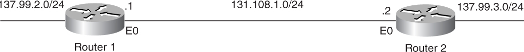
Figure 3-9 An Example of a Discontiguous Network
Figure 3-10 shows the flowchart to follow to solve this problem based on this cause.

Figure 3-10 Flowchart to Solve Why RIP Routes Don’t Show Up in a Routing Table
Debugs and Verification
Example 3-36 shows the configuration of Router R1 and Router R2. RIP is enabled on the Ethernet interfaces of R1 and R2 with the correct network statement.
Example 3-36 Configuration of R1 and R2 in a Discontiguous Network Environment
R2#
interface Loopback0
ip address 137.99.3.2 255.255.255.0
!
interface Ethernet0
ip address 131.108.1.2 255.255.255.0
!
router rip
network 131.108.0.0
network 137.99.0.0
!
R1#
interface Loopback0
ip address 137.99.2.1 255.255.255.0
!
interface Ethernet0
ip address 131.108.1.1 255.255.255.0
!
router rip
network 131.108.0.0
network 137.99.0.0
!
Example 3-37 shows the debug ip rip output for routers R1 and R2. Both debugs shows that the network 137.99.0.0 is being sent across.
Example 3-37 debug ip rip Output Showing That Both Routers Are Sending Summarized Major Network Addresses Across
R2#debug ip rip
RIP protocol debugging is on
RIP: received v1 update from 131.108.1.1 on Ethernet0
137.99.0.0 in 1 hops
RIP: sending v1 update to 255.255.255.255 via Ethernet0 (131.108.1.2)
RIP: build update entries
network 137.99.0.0 metric 1
R2#
R1#debug ip rip
RIP protocol debugging is on
R1#
RIP: received v1 update from 131.108.1.2 on Ethernet0
137.99.0.0 in 1 hops
RIP: sending v1 update to 255.255.255.255 via Ethernet0 (131.108.1.1)
RIP: build update entries
network 137.99.0.0 metric 1
As a result, both routers will ignore the 137.99.0.0 update from each other. Because R1 and R2 are already connected to this major network, they will ignore the update.
Solution
RIP is not installing the route 137.99.0.0 in the routing table because RIP doesn’t support discontiguous networks, as discussed in the beginning of the chapter. Several solutions to this problem exist. The quick solution is to configure a static route to the more specific subnets of 137.99.0.0 on each router. The second solution is to enable Version 2 of RIP. Another solution is to replace RIP with another IP routing protocol, such as OSPF, IS-IS, EIGRP, and so on, that supports discontiguous networks.
Example 3-38 shows the configuration change that is required for both Router R1 and Router R2 to fix the problem. This configuration adds the static route for the discontiguous subnets. Because you cannot pass the subnet information across in case of discontiguous networks in RIP-1, the only solution is to patch it with static routes.
Example 3-38 Static Route Configuration Should Solve This Problem
R1#
interface Loopback0
ip address 137.99.2.1 255.255.255.0
!
interface Ethernet0
ip address 131.108.1.1 255.255.255.0
!
router rip
network 131.108.0.0
network 137.99.0.0
!
ip route 137.99.3.0 255.255.255.0 131.108.1.2
R2#
interface Loopback0
ip address 137.99.3.2 255.255.255.0
!
interface Ethernet0
ip address 131.108.1.2 255.255.255.0
!
router rip
network 131.108.0.0
network 137.99.0.0
!
ip route 137.99.2.0 255.255.255.0 131.108.1.1
Example 3-39 shows the alternate solution to fix this problem, in the case of RIP-2. The solution is to run RIP-2 with no auto-summary configured. With the no-auto summary command added, RIP-2 will not autosummarize when crossing a major network boundary. The specific subnet information will be sent across.
Example 3-39 Configuration That Works Under RIP-2 in a Discontiguous Network Environment
router rip
version 2
network 131.108.0.0
network 137.99.0.0
no auto-summary
Example 3-40 shows the routing table of R2 after fixing this problem.
Example 3-40 R2 Routing Table Shows That 137.99.2.0/24 Is Learned Through RIP-2 After Configuring the no-auto summary Command
R2#show ip route 137.99.2.0
Routing entry for 13799.2.0/24
Known via "rip", distance 120, metric 1
Redistributing via rip
Last update from 131.108.1.1 on Ethernet0, 00:00:07 ago
Routing Descriptor Blocks:
* 131.108.1.1, from 131.108.1.1, 00:00:07 ago, via Ethernet0
Route metric is 1, traffic share count is 1
RIP Routes Not in the Routing Table—Cause: Invalid Source
When RIP tells the routing table to install the route, it performs a source-validity check. If the source is not on the same subnet as the local interface, RIP ignores the update and does not install routes in the routing table coming from this source address.
Figure 3-11 shows the network diagram for invalid source problem.

Figure 3-11 Network Diagram for Invalid Route Source
In Figure 3-11, Router 1’s Serial 0 interface is unnumbered to Loopback 0. Router 2’s serial interface is numbered. When Router 2 receives a RIP update from Router 1, it complains about the source validity because the source address is not on the same subnet as Router 2’s Serial 0 interface.
Figure 3-12 shows the flowchart to follow to solve this problem based on this cause.

Figure 3-12 Flowchart to Solve Why RIP Routes Don’t Show Up in a Routing Table
Debugs and Verification
Example 3-41 shows the configuration of both Router R2 and Router R1. In this configuration, R1’s Serial 0 interface is unnumbered to Loopback 0. R2’s Serial 0 interface is numbered.
Example 3-41 Configuration of R2 and R1 Showing That R1’s Serial 0 Interface Is Unnumbered and R2’s Isn’t
R2#
interface Loopback0
ip address 131.108.3.2 255.255.255.0
!
interface Serial0
ip address 131.108.1.2 255.255.255.0
!
router rip
network 131.108.0.0
!
R1#
interface Loopback0
ip address 131.108.2.1 255.255.255.0
!
interface Serial0
ip unnumbered Loopback0
!
router rip
network 131.108.0.0
!
The debug ip rip output in Example 3-42 shows that R2 is ignoring the RIP update from R1 because of a source validity check. The RIP update coming from R1 is not on the same subnet, so R2 will not install any routes in the routing table.
Example 3-42 debug ip rip Message Shows That R2 Is Receiving RIP Updates from a Different Source Address Than Its Own Interface
R2#debug ip rip
RIP protocol debugging is on
RIP: ignored v1 update from bad source 131.108.2.1 on Serial0
R2#
Solution
When one side is numbered and the other side is unnumbered, this check must be turned off. This is usually the case in a dialup situation when remotes are dialing into an access router. The access router’s dialup interface is unnumbered, and all remote routers get an IP address assigned on their dialup interfaces.
Example 3-43 shows the new configuration change on Router R2 to fix this problem.
Example 3-43 Configuration of R2 to Turn Off the Source Validity Check
R2#
interface Loopback0
ip address 131.108.3.2 255.255.255.0
!
interface Serial0
ip address 131.108.1.2 255.255.255.0
!
router rip
no validate-update-source
network 131.108.0.0
!
Example 3-44 shows that after changing the configurations of R2, the route gets installed in the routing table.
Example 3-44 R2 Routing Table After Turning Off Source Validity Check
R2#show ip route 131.108.2.0
Routing entry for 131.108.2.0/24
Known via "rip", distance 120, metric 1
Redistributing via rip
Last update from 131.108.1.1 00:00:01 ago
Routing Descriptor Blocks:
* 131.108.1.1, from 131.108.1.1, 00:00:07 ago
Route metric is 1, traffic share count is 1
RIP Routes Not in the Routing Table—Cause: Layer 2 Problem (Switch, Frame Relay, Other Layer 2 Media)
Sometimes, multicast/broadcast capability is broken at Layer 2, which further affects Layer 3 multicast. As a result, RIP fails to work properly. The Layer 3 broadcast/multicast is further converted into Layer 2 broadcast/multicast. If Layer 2 has problems in handling Layer 2 multicast/broadcast, the RIP updates will not be propagated. The debugs show that broadcast or multicast is being originated at one end but is not getting across.
Figure 3-13 shows the network diagram for Frame Relay problems while running RIP.

Figure 3-13 Two Routers Running RIP in a Frame Relay Environment
In Figure 3-13, Router 1 and Router 2 are connected through any Layer 2 media—for example, Frame Relay, X.25, Ethernet, FDDI, and so on.
Figure 3-14 shows the flowchart to follow to solve this problem based on this cause.
Figure 3-14 Flowchart to Solve Why RIP Routes Don’t Show Up in a Routing Table
Debugs and Verification
Example 3-45 shows the output of the debug ip rip command, which shows that R1 is sending and receiving RIP updates without any problem. On R2, RIP updates are being sent but not received. This means that the RIP update is being lost at Layer 2.
Example 3-45 debug ip packet Against access-list 100 Shows That R1 Is Sending RIP Updates on the Wire, and R2 Is Not Receiving It
R1#debug ip packet 100 detail
IP packet debugging is on (detailed) for access list 100
R1#
IP: s=131.108.1.1 (Ethernet0), d=255.255.255.255, len 132, sending broadcast/
multicast
UDP src=520, dst=520
IP: s=131.108.1.1 (Ethernet0), d=255.255.255.255, len 132, rcvd 2
UDP src=520, dst=520
R2#debug ip packet 100 detail
IP packet debugging is on (detailed) for access list 100
R2#
IP: s=131.108.1.2 (Ethernet0), d=255.255.255.255, len 132, sending broadcast/
multicast
UDP src=520, dst=520
IP: s=131.108.1.2 (Ethernet0), d=255.255.255.255, len 132, sending broadcast/
multicast
UDP src=520, dst=520
Example 3-46 shows access-list 100, which is used against the debug to look at the RIP broadcast/multicast specifically.
Example 3-46 access-list 100 Is Used Against the Debugs to Minimize the Traffic
access-list 100 permit ip any host 255.255.255.255
access-list 100 permit ip any host 224.0.0.9
Example 3-47 shows a way to find out if this is the problem when running RIP-2. Ping the multicast address of 224.0.0.9—if the neighbor doesn’t reply, this can mean that multicast is broken at Layer 2.
Example 3-47 Multicast Pings Are Failing, Which Means That R2’s Multicast Is Getting Lost at Layer 2
R2#ping 224.0.0.9
Type escape sequence to abort.
Sending 1, 100-byte ICMP Echos to 224.0.0.9, timeout is 2 seconds:
.....
R2#
Solution
RIP-1 sends an update on a broadcast address of 255.255.255.255. In the case of RIP-2, the update is sent on a multicast address of 224.0.0.9. If these two addresses get blocked at Layer 2 or are not being propagated at Layer 2, RIP will not function properly. Layer 2 could be a simple Ethernet switch, a Frame Relay cloud, a bridging cloud, and so on. Fixing the Layer 2 problem is beyond the scope of this book.
Example 3-48 shows that after fixing the Layer 2 problem, RIP routes get installed in the routing table.
Example 3-48 R2 Is Installing RIP Routes After Fixing the Layer 2 Problems
R2#show ip route 131.108.2.0
Routing entry for 131.108.2.0/24
Known via "rip", distance 120, metric 1
Redistributing via rip
Last update from 131.108.1.1 00:00:01 ago
Routing Descriptor Blocks:
* 131.108.1.1, from 131.108.1.1, 00:00:07 ago
Route metric is 1, traffic share count is 1
RIP Routes Not in the Routing Table—Cause: Offset List Has a Large Metric Defined
Offset lists are used to increase the metric value of RIP updates coming in or going out. The use of an offset list can directly influence the routing table. This list can be applied on selected networks that can be defined in an access list. If the offset value is a large number, such as 14 or 15, the RIP metric will reach infinity when it crosses a couple of routers. That’s why the offset list value should be kept to a minimum value.
Figure 3-15 shows a network setup that can produce a problem in the case of a misconfigured offset list.

Figure 3-15 Network Topology Used for Misconfigured Offset Lists Problem Reproduction
Example 3-49 shows that the specific router 131.108.6.0 is not in the routing table of R2.
Example 3-49 R2’s Routing Table Missing the Subnet That Is Off R3
R2#show ip route 131.108.6.0
% Subnet not in table
Figure 3-16 shows the flowchart to follow to solve this problem based on this cause.

Figure 3-16 Flowchart to Solve Why RIP Routes Don’t Show Up in a Routing Table
Debugs and Verification
Troubleshooting should be done to investigate RIP’s normal behavior.
Example 3-50 shows that R2 is receiving other RIP routes, but not 131.108.6.0/24.
Example 3-50 R2 Is Missing 131.108.6.0/24 from Its Routing Table
R2#show ip route RIP
131.108.0.0/24 is subnetted, 4 subnets
R 131.108.5.0 [120/1] via 131.108.1.1, 00:00:06, Ethernet1
R 131.108.3.0 [120/1] via 131.108.1.1, 00:00:06, Ethernet1
This shows that problem is with 131.108.6.0/24, not with RIP in general. The reason is that R3 is receiving other RIP routes from R1, so the RIP update that is coming from R1 is working fine.
Example 3-51 shows the routing table of R1, where 131.108.6.0/24 is present in the routing table.
Example 3-51 R1 Sees 131.108.6.0/24 in Its Routing Table
R1#show ip route 131.108.6.0
Routing entry for 131.108.6.0/24
Known via "rip", distance 120, metric 1
So why is R2 not installing 131.108.6.0/24? This could be because of one of the following reasons:
• R1 is not advertising to R2.
• R1 is advertising, but R2 is not receiving.
• R2 is receiving but is discarding it because of an infinite metric.
The simplest way to troubleshoot such problems is quick configuration examination.
Example 3-52 shows the configuration of Router R1.
Example 3-52 The Offset List Has a Large Value Configured on R1 for 131.108.6.0/24
R1#
router rip
version 2
offset-list 1 out 15 Ethernet0/1
network 131.108.0.0
!
access-list 1 permit 131.108.6.0
The administrator has configured an offset list with a very large metric. The offset list is used to change the metric of RIP update.
From the configuration, you can surmise that any update that passes access-list 1 will have 15 added in the metric. In Example 3-52, access-list 1 permits 131.108.6.0. This means that the metric of 131.108.6.0 is 16, which, to RIP, is an infinite metric; upon receiving it, R2 will reject it.
To verify this, run the debug ip rip command, as demonstrated in Example 3-53.
Example 3-53 debug ip rip on R2 Shows That 131.108.6.0 Is Received with an Infinite Metric
R2#debug ip RIP
RIP: received v2 update from 131.108.1.1 on Ethernet1
131.108.6.0/24 -> 0.0.0.0 in 16 hops (inaccessible)
Because 16 is the infinite metric for RIP, R2 will reject 131.108.6.0/24 from going in the routing table.
Solution
Typically, offset lists are not used in RIP networks. When the network has redundant equal-hop (cost) paths and the administrator wants one route preferred over another, an offset list can be used.
For example, suppose that two links exist between R1 and R2. One of the links could be either congested or experiencing delay.
The administrator might want to shift the IP traffic for certain destination subnets to a noncongested link for a short time, to get better throughput and to alleviate some of the congestion. An offset list is an easy way to achieve this by making the RIP metric higher for the subnets on the congested interface.
Example 3-54 shows the new configuration of Router R1.
To fix the problem, configure an offset value so that the hop count won’t reach its limit.
Example 3-54 New Configuration on R1 with Appropriate Offset List Value
R1#
router rip
version 2
offset-list 1 out 1 Ethernet0/1
network 131.108.0.0
!
access-list 1 permit 131.108.6.0
Example 3-55 shows the routing table of Router R2 after fixing the problem.
Example 3-55 R2’s Routing Table Shows the Entry for 131.108.6.0/24 After Configuring the Proper Offset List
R2#show ip route 131.108.6.0
Routing entry for 131.108.6.0/24
Known via "rip", distance 120, metric 1
RIP Routes Not in the Routing Table—Cause: Routes Reached RIP Hop Count Limit
The RIP metric can go up to a maximum of 15 hops. If a network has more than 15 hops, RIP is not a suitable protocol for it.
Figure 3-17 shows a network setup that produces a RIP hop-count limit problem.

Figure 3-17 Network Setup That Can Produce a RIP Hop-Count Limit Problem
R2 is receiving an update for a RIP route, which is several (more than 15) hops away. R2 doesn’t install that route in the routing table, as demonstrated in the output in Example 3-56.
Example 3-56 R2’s Routing Table Is Missing the Route for 131.108.6.0
R2#show ip route 131.108.6.0
% Subnet not in table
Figure 3-18 shows the flowchart to solve this problem.

Figure 3-18 Flowchart to Solve Why RIP Routes Don’t Show Up in a Routing Table
Debugs and Verification
The most logical way to start troubleshooting this problem is to look at R1 and determine whether R1 is receiving 131.108.6.0/24.
Example 3-57 shows that Router R1 is receiving RIP routes for 131.108.6.0/24.
Example 3-57 R1’s Routing Table Has 131.108.6.0/24 with a Metric of 15 (Maximum RIP Metric)
R1#show ip route 131.108.6.0
Routing entry for 131.108.6.0/24
Known via "rip", distance 120, metric 15
R1 is receiving the route in question, but with a metric of 15. R1 will add 1 more to 15 when advertised to R2, which will result in an infinite metric, consequently preventing the route from being placed in the routing table.
To prove this, in R1, you can run the debug ip rip command to view the process in real time.
Example 3-58 shows the output of debug ip rip on Router R1.
Example 3-58 debug ip rip Output Shows That R1 Is Advertising 131.108.6.0 with a Metric of 16 (Infinity)
R1#debug ip rip
RIP protocol debugging is on
RIP: sending v2 update to 224.0.0.9 via Ethernet1 (131.108.1.1)
131.108.6.0/24 -> 0.0.0.0, metric 16, tag 0
Example 3-59 shows the output of debug ip rip on Router R2. Router R2 receives this update and discards it because the metric shows that this network is infinitely far away and, therefore, unreachable.
Example 3-59 debug ip rip Output on R2 Shows That R2 Is Receiving Routes with an Infinite Metric
R2#debug ip rip
RIP protocol debugging is on
RIP: received v2 update from 131.108.1.1 on Ethernet1
131.108.6.0/24 -> 0.0.0.0 in 16 hops (inaccessible)
Solution
This is a classical RIP problem in which a route passes through more than 15 devices. IP networks these days usually have more than 15 routers. There is no way to overcome this behavior other than to pick a routing protocol that does not have a 15-hop limitation. You should use OSPF, EIGRP, or IS-IS instead.
Problem: RIP Is Not Installing All Possible Equal-Cost Paths—Cause: maximum-path Command Restricts RIP from Installing More Than One Path
By default, Cisco routers support only four equal paths for the purpose of load balancing. The maximum-path command can be used for up to six equal-cost paths. If the command is not configured properly, it can cause a problem, as discussed in this section. When configured improperly, the maximum-path command allows only one path to the destination, even though more than one path exists. Configuring the command as maximum-path 1 should be done only when load balancing is not desired.
Figure 3-19 and Example 3-60 provide a network scenario that will be used as the basis for troubleshooting when the maximum-path command restricts RIP from installing more than one path, resulting in the omission of all possible equal-cost paths. The sections that follow carefully dissect how to troubleshoot this problem.

Figure 3-19 RIP Network Vulnerable to an Equal-Cost Path Problem
Figure 3-19 shows the network setup that produces the problem of RIP not installing all possible equal-cost paths.
Example 3-60 shows the routing table of Router R1. Only one route is being installed in the routing table. By default, any routing protocol supports equal-cost multipaths (load balancing). If more than one equal path exists, it must be installed in the routing table.
Example 3-60 R1 Installs Only One Path for 131.108.2.0/24
R1#show ip route rip
131.108.0.0/24 is subnetted, 1 subnets
R 131.108.2.0 [120/1] via 131.108.5.3, 00:00:09, Ethernet2
Figure 3-20 shows the flowchart to follow to solve this problem based on this cause.

Figure 3-20 Flowchart to Solve Why RIP Routes Don’t Show Up in a Routing Table
Debugs and Verification
Example 3-61 shows the output of debug ip rip on Router R1. The output shows that Router R1 is receiving two equal-cost routes.
Example 3-61 debug ip rip Output on R1 Shows R1 Receiving Two Updates for the 131.108.2.0 Network
R1#debug ip rip
RIP protocol debugging is on
R1#
RIP: received v2 update from 131.108.5.3 on Ethernet2
131.108.2.0/24 -> 0.0.0.0 in 1 hops
RIP: received v2 update from 131.108.1.2 on Ethernet1
131.108.2.0/24 -> 0.0.0.0 in 1 hops
Only one route is installed in the routing table. You see only one route in the routing table instead of two because operator has configured maximum-paths 1 in the configuration.
Example 3-62 shows the current configuration for Router R1.
Example 3-62 R1 Is Configured with maximum-path 1
R1#
router rip
version 2
network 131.108.0.0
maximum-paths 1
Solution
By default, Cisco IOS Software allows up to four equal-cost routes to be installed in the routing table. This could be increased up to six routes if configured as in Example 3-63.
Example 3-63 shows the configuration that installs six equal-cost path routes in the routing table.
Example 3-63 Allowing the Maximum of Six Paths in the Routing Table
R1#
router rip
maximum-paths 6
This example makes more sense when you have more than four paths and only four are getting installed in the routing table. Because four equal-cost routes is a default, maximum-paths needs to be increased to accommodate the fifth and possibly sixth route.
Troubleshooting RIP Routes Advertisement
All the problems discussed so far deal with the problem on the receiving end or the problem in the middle (Layer 2).
A third possible cause exists when routes are not being installed in the routing table. The sender could be having a problem sending RIP updates for some reason. As a result, the receiver cannot install the RIP routes in the routing table. This section talks about the things that can go wrong on the sender’s side.
This section discusses some of the possible scenarios that can prevent RIP routes from being advertised. Some cases overlap with router installation problems—for example, missing network statement(s) or an interface that is down. This section assumes that, after troubleshooting the problems previously addressed in the “Troubleshooting RIP Routes Installation” section, the problems persist. This section presents recommendations on where to go next to resolve those issues.
Two of the most prevalent problems that can go wrong on the sender’s end deal with RIP route advertisement:
• The sender is not advertising RIP routes.
• Subnetted routes are missing.
Problem: Sender Is Not Advertising RIP Routes
Typically, an IP network running RIP has routers that have a consistent view of the routing table. In other words, all routers have routing tables that contain reachability information for all the IP subnets of the network. This might differ in cases when filtering of certain subnets is done at some routers and not at others. Ideally, all RIP routers have routes of the complete network.
When the routing information differs from one router to the other, one of two possibilities could exist:
• Some routers are not advertising the RIP routes.
• Some routers are not receiving the RIP routes.
This section deals with problems in sending RIP routes.
Figure 3-21 provides a network scenario that will be used as the basis for troubleshooting a majority of following causes of the problem of the sender not advertising RIP routes:
• Missing or incorrect network statement
• Outgoing interface that is down
• distribute-list out blocking the routes
• Advertised network interface that is down
• Outgoing interface defined as passive
• Broken multicast capability (encapsulation failure in Frame Relay)
• Misconfigured neighbor statement
• Advertised subnet is VLSM
• Split horizon enabled

Figure 3-21 Network Setup in Which Router R1 Is Not Sending RIP Routes Toward R2
Figure 3-21 shows the network setup in which Router R1 is not sending RIP routes toward R2.
The sections that follow carefully dissect how to troubleshoot this problem based on specific causes.
Sender Is Not Advertising RIP Routes—Cause: Missing or Incorrect network Statement
One of the requirements for enabling RIP on a router’s interface is to add the network statement under the router rip command. The network statement decides which interface RIP should be enabled on. If the network statement is misconfigured or not configured, RIP will not be enabled on that interface and RIP routes will not be advertised out that interface.
Figure 3-22 shows the flowchart to follow to fix this problem.

Figure 3-22 Flowchart to Solve Why the Sender Is Not Advertising RIP Routes
Debugs and Verifications
Example 3-64 shows the current configuration for R1.
Example 3-64 R1 Configuration Shows the Misconfigured network Statement
R1#
interface Loopback0
ip address 131.108.2.1 255.255.255.0
!
interface Ethernet0
ip address 131.108.1.1 255.255.255.0
!
router rip
network 131.107.0.0
The network statement is incorrectly configured under router rip in Example 3-64. Instead of 131.108.0.0, 131.107.0.0 is configured. This will not enable RIP on the interface, and no updates will be sent.
Solution
Sometimes, a classless statement is configured under router rip, assuming that it will cover all the networks—for example:
router rip
network 131.0.0.0
The network statement will not cover 131.0.0.0 through 131.255.255.255 because 131.0.0.0 is a classless network and RIP is a classful protocol. Similarly, if you have multiple Class C addresses, you cannot use one network statement to cover all the addresses that you own. For example, suppose that you own 200.1.1.0 through 200.1.4.0. This doesn’t mean that you can use the following command syntax:
router rip
network 200.1.0.0
The network statement here is meaningless for RIP-1 because RIP-1 is a classful protocol. The correct way to advertise all four networks in RIP is as follows:
router rip
network 200.1.1.0
network 200.1.2.0
network 200.1.3.0
network 200.1.4.0
Example 3-65 shows the corrected configuration for R1.
Example 3-65 Correcting the network Statement in the R1 Configuration
R1#
interface Loopback0
ip address 131.108.2.1 255.255.255.0
!
interface Ethernet0
ip address 131.108.1.1 255.255.255.0
!
router rip
network 131.108.0.0
Example 3-66 shows the routing table of Router R2, showing the learned RIP route.
Example 3-66 R2 Routing Table Shows That the RIP Routes Are Learned After Correcting the network Statement
R2#show ip route 131.108.2.0
Routing entry for 131.108.2.0/24
Known via "rip", distance 120, metric 1
Redistributing via rip
Last update from 131.108.1.1 on Ethernet0, 00:00:11 ago
Routing Descriptor Blocks:
* 131.108.1.1, from 131.108.1.1, 00:00:11 ago, via Ethernet0
Route metric is 1, traffic share count is 1
Sender Is Not Advertising RIP Routes—Cause: Outgoing Interface Is Down
RIP is the routing protocol that runs on Layer 3. RIP cannot send updates across an interface if the outgoing interface is down. There can be a variety of possible causes for the outgoing interface being down:
• Interface is up, line protocol is down
• Interface is down, line protocol is down
• Interface is administratively down, line protocol is down
If the outgoing interface shows any of these symptoms, RIP will not be capable of sending any updates across the network. The main thing to note here is that, with any of these potential causes, the line protocol will always show down. This is the most important information to determine Layer 2 connectivity.
Figure 3-23 shows the flowchart to follow to solve this problem based on this cause.

Figure 3-23 Flowchart to Solve Why the Sender Is Not Advertising RIP Routes
Debugs and Verification
Example 3-67 shows that the interface Ethernet 0 is down.
Example 3-67 Outgoing Interface Ethernet 0 of R1 Shows That the Line Protocol Is Down
R1#show interface ethernet 0
Ethernet0 is up, line protocol is down
Hardware is Lance, address is 0000.0c70.d31e (bia 0000.0c70.d31e)
Internet address is 131.108.1.1/24
Example 3-68 shows the debug ip rip output. In this debug, R1 is not sending or receiving any RIP updates because Layer 2 is down.
Example 3-68 debug ip rip Output Reveals That Nothing Is Being Sent or Received on R1’s Ethernet0 Interface
R1#debug ip rip
RIP protocol debugging is on
R1#
In the debug, there are no outputs because of this problem.
Solution
RIP runs above Layer 2. RIP cannot send or receive any routes if Layer 2 is down.
To correct this problem, Layer 2 or Layer 1 must be corrected. Sometimes, the problem could be as simple as loose cables or a bad cable that must be replaced, or it could be as complex as bad hardware, in which case hardware must be replaced.
Example 3-69 shows the interface Ethernet 0 after fixing the Layer 2 problem.
Example 3-69 R1’s Outgoing Interface Ethernet0 Is Up After Fixing the Layer 2 Issue
R1#
Ethernet0 is up, line protocol is up
Hardware is Lance, address is 0000.0c70.d31e (bia 0000.0c70.d31e)
Internet address is 131.108.1.1/24
Example 3-70 shows the routing table of R2.
Example 3-70 1’s Ethernet0 Interface Is Up, So RIP Is Sending Updates and R2 Has RIP Routes in Its Routing Table
R2#show ip route 131.108.2.0
Routing entry for 131.108.2.0/24
Known via "rip", distance 120, metric 1
Redistributing via rip
Last update from 131.108.1.1 on Ethernet0, 00:00:07 ago
Routing Descriptor Blocks:
* 131.108.1.1, from 131.108.1.1, 00:00:07 ago, via Ethernet0
Route metric is 1, traffic share count is 1
Sender Is Not Advertising RIP Routes—Cause: distribute-list out Is Blocking the Route
distribute-list out is used to filter any routes that will be sent out an interface. If a receiver is complaining about missing routes that should be received, make sure that the routes are not being filtered through distribute-list out. If this is the case, you must modify the access list.
Figure 3-24 shows the flowchart to follow to fix this problem.

Figure 3-24 Flowchart to Solve Why the Sender Is Not Advertising RIP Routes
Debugs and Verification
Example 3-71 shows the configuration of Router R1. In this configuration, access-list 1 does not explicitly permit the 131.108.0.0 network, so R1 will not be allowed to advertise any 131.108.X.X network, including 131.108.2.0/24.
Example 3-71 access-list 1 Does Not Permit the 131.108.0.0 Network
R1#
interface Loopback0
ip address 131.108.2.1 255.255.255.0
!
interface Ethernet0
ip address 131.108.1.1 255.255.255.0
!
router rip
network 131.108.0.0
distribute-list 1 out
!
access-list 1 permit 131.107.0.0 0.0.255.255
Solution
When using a distribute list, you should always double-check your access list to make sure that the networks that are supposed to be permitted are explicitly permitted in the access list. If not, they will be denied. In the configuration example in Example 3-72, the access list is permitting only 131.107.0.0. An implicit deny any at the end of each access list causes the 131.108.0.0 network to be denied. To fix this problem, permit 131.108.0.0 in access-list 1, as shown in Example 3-72.
Example 3-72 Reconfiguring access-list 1 to Permit Network 131.108.0.0
interface Loopback0
ip address 131.108.2.1 255.255.255.0
!
interface Ethernet0
ip address 131.108.1.1 255.255.255.0
!
router rip
network 131.108.0.0
distribute-list 1 out
!
access-list 1 permit 131.108.0.0 0.0.255.255
Example 3-73 shows the routing table of Router R2.
Example 3-73 R2 Routing Table Shows the Entry for the 131.108.2.0 Network After Permitting It in access-list 1
R2#show ip route 131.108.2.0
Routing entry for 131.108.2.0/24
Known via "rip", distance 120, metric 1
Redistributing via rip
Last update from 131.108.1.1 on Ethernet0, 00:00:07 ago
Routing Descriptor Blocks:
* 131.108.1.1, from 131.108.1.1, 00:00:07 ago, via Ethernet0
Route metric is 1, traffic share count is 1
Sender Is Not Advertising RIP Routes—Cause: Advertised Network Interface Is Down
The network that is being advertised might be down, and the connected route has been removed from the routing table. In this situation, RIP will start advertising that network with an infinite metric of 16; after the hold-down timer has expired, it will no longer advertise this network. As soon as the advertised network comes up, RIP will start advertising it again in its updates.
Figure 3-25 shows the flowchart to follow to fix this problem.

Figure 3-25 Flowchart to Solve Why the Sender Is Not Advertising RIP Routes
Debugs and Verification
Example 3-74 shows that the line protocol of R1’s Ethernet 1 interface is down, indicating that there is something wrong at Layer 2. This is the interface that is directly attached to the network that needs to be advertised. Therefore, that network cannot be advertised to neighboring routers.
Example 3-74 show interface Output Displays That the Line Protocol of the Advertised Network Is Down
R1#show interface Ethernet 1
Ethernet1 is up, line protocol is down
Hardware is Lance, address is 0000.0c70.d51e (bia 0000.0c70.d51e)
Internet address is 131.108.2.1/24
When the advertised network’s interface goes down, RIP will detect the down condition. RIP will no longer advertise that network in the RIP update. In Example 3-74, interface Ethernet 1 is down, so RIP will no longer advertise 131.108.2.0/24 in its update.
Solution
You must correct this problem at Layer 2 or Layer 1. Sometimes, the problem could be as simple as loose cables, or it could be as complex as bad hardware, in which case the hardware must be replaced. After fixing the Layer 2 problem, reissue the show interface command to view the current status, to verify that it has changed state to up.
Example 3-75 shows that the advertised network interface line protocol is up.
Example 3-75 show interface Output Displays That the Line Protocol of Ethernet1 Is Up After Fixing the Layer 2 Issue
R1#show interface Ethernet 1
Ethernet1 is up, line protocol is up
Hardware is Lance, address is 0000.0c70.d51e (bia 0000.0c70.d51e)
Internet address is 131.108.2.1/24
When the interface is active again, RIP will begin to advertise that network in its periodic updates. Example 3-76 shows that the route that was down is back in the routing table of R2.
Example 3-76 show ip route Output Displays That R2’s Routing Table Indicates the Network Again After the Layer 2 Issue Is Resolved
R2#show ip route 131.108.2.0
Routing entry for 131.108.2.0/24
Known via "rip", distance 120, metric 1
Redistributing via rip
Last update from 131.108.1.1 on Ethernet0, 00:00:07 ago
Routing Descriptor Blocks:
* 131.108.1.1, from 131.108.1.1, 00:00:07 ago, via Ethernet0
Route metric is 1, traffic share count is 1
Sender Is Not Advertising RIP Routes—Cause: Outgoing Interface Is Defined Passive
A situation might arise in which a router has a complete RIP routing table, but it is not advertising to other routers running RIP. This occurs when not all routers in a RIP network have complete routing tables, resulting in lacking IP connectivity from one part of the network to the other. If the outgoing interface is defined as passive, it will not advertise any RIP updates on that interface.
Figure 3-26 shows the flowchart to follow to fix this problem.

Figure 3-26 Flowchart to Solve Why the Sender Is Not Advertising RIP Routes
Debugs and Verification
Example 3-77 shows the output of show ip protocols, which shows that the outgoing interface is defined as a passive interface.
Example 3-77 show ip protocols Output Reveals That the Outgoing Interface on R1 Is Passive
R1#show ip protocols
Routing Protocol is "rip"
Sending updates every 30 seconds, next due in 26 seconds
Invalid after 180 seconds, hold down 180, flushed after 240
Outgoing update filter list for all interfaces is
Incoming update filter list for all interfaces is
Redistributing: rip
Default version control: send version 1, receive any version
Interface Send Recv Key-chain
Loopback0 1 1 2
Routing for Networks:
131.108.0.0
Passive Interface(s) Ethernet0
Routing Information Sources:
Gateway Distance Last Update
131.108.1.2 120 00:00:26
Distance: (default is 120)
Example 3-78 shows the configuration of Router R1, which shows that the outgoing interface is defined as passive.
Example 3-78 Configuring the passive interface Command in RIP
router rip
passive-interface Ethernet0
network 131.108.0.0
Solution
When an interface is defined as a passive interface under RIP, RIP will receive updates on that interface but will not send any updates.
In Example 3-78, the interface Ethernet 0 is defined as passive, so R1 is not sending any updates on Ethernet 0. Sometimes, some networks should be advertised and others should be filtered. In this type of situation, passive interfaces should not be used. Distribute lists, used to selectively filter updates, are a better solution in that case.
Assume that passive-interface was configured by mistake. Take this command out of the configuration to solve this problem using the no form of the command.
Example 3-79 shows the new configuration to solve this problem.
Example 3-79 Correcting the passive-interface Problem
router rip
network 131.108.0.0
Example 3-80 shows the routing table of R2 after fixing the problem.
Example 3-80 R2 Routing Table After Removing the passive-interface Command
R2#show ip route 131.108.2.0
Routing entry for 131.108.2.0/24
Known via "rip", distance 120, metric 1
Redistributing via rip
Last update from 131.108.1.1 on Serial0, 00:00:07 ago
Routing Descriptor Blocks:
* 131.108.1.1, from 131.108.1.1, 00:00:07 ago, via Serial0
Route metric is 1, traffic share count is 1
Sender Is Not Advertising RIP Routes—Cause: Broken Multicast Capability (Frame Relay)
In some networking scenarios, router interfaces do not automatically propagate multicast and broadcast traffic unless configured to do so. This could be a major problem because RIP-1 updates are sent at a broadcast address and RIP-2 uses multicast to exchange routes. No routing information will propagate across the network unless broadcast and multicast features are enabled on such interfaces. Nonbroadcast multiaccess (NBMA) Frame Relay is a prime example of a networking environment in which interfaces exhibit this behavior.
Figure 3-27 shows a network setup that is deliberately configured with broken multicast to illustrate the example of how Frame Relay RIP updates will not go across R1.

Figure 3-27 NBMA Frame Relay Network Vulnerable to Broken Multicast Capability Problems
In Figure 3-27, Router 1 and Router 2 are connected through Frame Relay. Router 1 is not advertising RIP routes toward Router 2.
Figure 3-28 shows the flowchart to follow to solve this problem based on this cause.

Figure 3-28 Flowchart to Solve Why the Sender Is Not Advertising RIP Routes
Debugs and Verification
Example 3-81 shows the configuration of Router R1. In this example, Frame Relay provides the Layer 2 encapsulation. In this configuration, the frame-relay map statement doesn’t have the keyword broadcast at the end. As a result, all broadcast/multicast traffic will be prohibited from crossing the NBMA network. The broadcast keyword tells the router to replicate the necessary broadcasts and send them across the specified circuits.
Example 3-81 R1’s frame-relay map Statement Lacks the broadcast Keyword
R1#
interface Serial3
ip address 131.108.1.1 255.255.255.0
encapsulation frame-relay
frame-relay map ip 131.108.1.2 16
!
Example 3-83 shows output from debug ip packet. This debug includes only the broadcast traffic source from R1. As shown in Example 3-82, R1 is configured with access-list 100.
Example 3-82 Configuration in R1 of access-list 100 to Limit debug Output
R1#:
access-list 100 permit ip host 131.108.1.1 host 255.255.255.255
R1 is configured with access-list 100, which permits all packets from source 131.108.1.1 destined to the broadcast address of 255.255.255.255. In Example 3-83, R1 runs debug ip packet detail with access-list 100 to limit traffic destined to 255.255.255.255 with R1 as the source. The debug output in Example 3-83 shows that there are encapsulation failures, indicating that they cannot be placed in the appropriate Layer 2 frame.
Example 3-83 debug ip packet Output on R1 Reveals Encapsulation Failure for RIP Updates
R1#debug ip packet 100 detail
IP packet debugging is on (detailed) for access list 100
R1#
IP: s=131.108.1.1 (local), d=255.255.255.255 (Serial3), len 112, sending broad/
multicast
UDP src=520, dst=520
IP: s=131.108.1.1 (local), d=255.255.255.255 (Serial3), len 112, encapsulation
failed
UDP src=520, dst=520
Solution
When RIP is running in a Frame Relay (NBMA) environment, Layer 2 must be configured to support broadcast traffic; otherwise, RIP updates will not get across. When static map-ping is used, make sure to add the broadcast keyword at the end of a frame-relay map statement.
Example 3-84 shows the new configuration of Router R1 with the corrected frame-relay map statement.
Example 3-84 Corrected Configuration to Enable Broadcast Traffic to Go Across an NBMA Environment
R1#:
interface Serial3
ip address 131.108.1.1 255.255.255.0
encapsulation frame-relay
frame-relay map ip 131.108.1.2 16 broadcast
!
Example 3-85 shows the routing table of R2 with RIP routes.
Example 3-85 R2 Routing Table with RIP Routes After the Corrected frame-relay map Statement for Router R1
R2#show ip route 131.108.2.0
Routing entry for 131.108.2.0/24
Known via "rip", distance 120, metric 1
Redistributing via rip
Last update from 131.108.1.1 on Serial0, 00:00:07 ago
Routing Descriptor Blocks:
* 131.108.1.1, from 131.108.1.1, 00:00:07 ago, via Serial0
Route metric is 1, traffic share count is 1
Sender Is Not Advertising RIP Routes—Cause: Misconfigured neighbor Statement
In a nonbroadcast environment, RIP utilizes a unicast method to send RIP updates. To send unicast RIP updates, neighbor statements must be configured carefully. If the neighbor address is configured incorrectly in the neighbor statement, RIP will not send the unicast update to the neighbor.
Figure 3-29 shows the flowchart to follow to solve this problem based on this cause.

Figure 3-29 Flowchart to Solve Why the Sender Is Not Advertising RIP Routes
Debugs and Verification
Example 3-86 shows the RIP configuration in Router R1. The configuration shows that the neighbor statement is configured incorrectly. Instead of 131.108.1.2, it’s pointing to 131.108.1.3, which doesn’t exist.
Example 3-86 Router R1 RIP Configuration with Incorrectly Configured neighbor Statement
router rip
network 131.108.0.0
neighbor 131.108.1.3
Solution
In Example 3-86, RIP is sending a unicast update to a neighbor address of 131.108.1.3, which doesn’t exist.
To solve the problem, the neighbor statement must be configured properly.
Example 3-87 shows the corrected configuration of Router R1.
Example 3-87 Router R1 Configuration with the Correct neighbor Statement
R1# router rip
network 131.108.0.0
neighbor 131.108.1.2
Example 3-88 shows the RIP routes installed in R2’s routing table.
Example 3-88 R2 Routing Table Shows the RIP Entry After Correcting the RIP neighbor Statement
R2#show ip route 131.108.2.0
Routing entry for 131.108.2.0/24
Known via "rip", distance 120, metric 1
Redistributing via rip
Last update from 131.108.1.1 on Serial0, 00:00:07 ago
Routing Descriptor Blocks:
* 131.108.1.1, from 131.108.1.1, 00:00:07 ago, via Serial0
Route metric is 1, traffic share count is 1
Sender Is Not Advertising RIP Routes—Cause: Advertised Subnet Is VLSM
In almost all IP networks, IP addresses are efficiently utilized by doing variable-length subnet masking (VLSM) of the original IP block. Because RIP-1 does not support VLSM routing, routing VLSM routes becomes a common issue with RIP running networks.
Figure 3-30 shows the network setup, which produces problems because of the existence of a VLSM. The figure shows that Router 1 has an interface whose mask is /25. Note that 131.108.0.0 is variably subnetted to two different masks, 131.108.1.0/24 and 131.108.2.0/25.

Figure 3-30 VLSM Network Example Producing Problems with RIP
RIP-1 cannot advertise the mask of a subnet, so it cannot support VLSM and cannot advertise /25 to an RIP interface whose mask is /24.
Figure 3-31 shows the flowchart to follow to correct this problem.

Figure 3-31 Flowchart to Solve Why the Sender Is Not Advertising RIP Routes
Debugs and Verification
Example 3-89 shows that a loopback interface on R1 is configured for a /25 (255.255.255.128) subnet mask; the interface that will be sourcing RIP update has a /24 (255.255.255.0) mask.
Example 3-89 Configuration to Show VLSM Subnets
R1#:
interface Loopback0
ip address 131.108.2.1 255.255.255.128
!
interface Ethernet0
ip address 131.108.1.1 255.255.255.0
!
router rip
network 131.108.0.0
Solution
RIP-1 is not designed to carry subnet mask information. Therefore, any subnet that is using a different mask than the interface that will be sourcing the RIP update will not be advertised by RIP. RIP actually performs a check before sending an update, to make sure that the subnet that will be advertised by RIP has the same subnet mask as the interface that will be sourcing the RIP update. If the mask is different, RIP actually drops the update and will not advertise it.
To solve the problem, either change the subnet mask so that it matches the interface that will be sourcing the RIP update or change the protocol to RIP-2, which does support VLSM.
Example 3-90 shows the configuration changes that correct the problem.
Example 3-90 Configuring RIP to Advertise VLSM Routes
R1#:
interface Loopback0
ip address 131.108.2.1 255.255.255.0
!
interface Ethernet0
ip address 131.108.1.1 255.255.255.0
!
router rip
version 2
network 131.108.0.0
Example 3-91 shows the routing table of Router R2 after correcting the problem.
Example 3-91 Router R2 Routing Table After Resolving the VLMS Support Problem
R2#show ip route 131.108.2.0
Routing entry for 131.108.2.0/25
Known via "rip", distance 120, metric 1
Redistributing via rip
Last update from 131.108.1.1 on Ethernet0, 00:00:07 ago
Routing Descriptor Blocks:
* 131.108.1.1, from 131.108.1.1, 00:00:07 ago, via Ethernet0
Route metric is 1, traffic share count is 1
Sender Is Not Advertising RIP Routes—Cause: Split Horizon Is Enabled
Split horizon is a feature in RIP to control routing loops. In some situations, it is necessary to enable split horizon to avoid loops. For example, split horizon is necessary in a normal situation when a RIP update is received on an interface and is not sent out on the same interface. Split horizon must be disabled in other environments, such as a hub-and-spoke Frame Relay environment in which spokes have no circuit between them and they go through the hub router, as shown in Figure 3-32.

Figure 3-32 Hub-and-Spoke Frame Relay Network Requiring Disabling Split Horizon
Another unique situation worth mentioning is one in which a router has an external route that has a next-hop address also known through some interface where other RIP routers are sitting. When those external routes are redistributed into RIP, the router doesn’t advertise that route out the same interface because split horizon is enabled. Also, if a secondary address is configured under an interface, split horizon must be turned off on that interface; otherwise, that secondary address will not be advertised out that interface to other routers.
Figure 3-33 shows the network setup that produces problems when split horizon is enabled. Router 1 is not advertising all RIP routes to Router 3.

Figure 3-33 Split Horizon–Enabled Network Vulnerable to RIP Problems
Figure 3-34 shows the flowchart to follow to fix this problem.

Figure 3-34 Flowchart to Solve Why the Sender Is Not Advertising RIP Routes
Debugs and Verification
Example 3-92 shows the current configuration of R1.
Example 3-92 166.166.166.0/24 Is Being Redistributed into RIP on R1
R1#
router rip
redistribute static
network 131.108.0.0
!
ip route 155.155.0.0 255.255.0.0 10.10.10.4
ip route 166.166.166.0 255.255.255.0 131.108.1.3
Example 3-93 shows that the route 166.166.166.0/24 is not in the routing table of Router R2; however, 155.155.155.0/24 does show up in the routing table.
Example 3-93 R2 Routing Table Does Not Show Route 166.166.166.0/24
R2#show ip route rip
R 155.155.0.0/16 [120/1] via 131.108.1.1, 00:00:07, Ethernet0
Example 3-94 shows the debug ip rip output on Router R1. R1 is advertising only 155.155.0.0/16, not 166.166.166.0/24. In R2’s routing table, no route exists for 166.166.166.0/24.
Example 3-94 debug ip rip Output Displays 166.166.166.0 Is Not Being Advertised by R1
R1#debug ip rip
RIP protocol debugging is on
RIP: sending v1 update to 255.255.255.255 via Ethernet0 (131.108.1.1)
RIP: build update entries
network 155.155.0.0 metric 1
Solution
This problem occurs because the next hop of 166.166.166.0/24 is 131.108.1.2. With split horizon, RIP will suppress this update from going out the same interface that 166.166.166.0/24 is learned. Notice that the route 155.155.155.0/24 was advertised by R1 because the next-hop address of that route was 10.10.10.4, which is a different interface on R1.
The solution lies in turning off split horizon on the Ethernet 0 interface of R1.
A similar situation would arise if 166.166.166.0/24 was defined as a secondary interface address on R1, which will not advertise this secondary interface address in its RIP update unless split horizon is turned off.
Example 3-95 shows the new configuration on Router R1 to solve this problem.
Example 3-95 Disabling Split-Horizon on R1’s Ethernet 0 Interface
R1#
interface Ethernet0
ip address 131.108.1.1 255.255.255.0
no ip split-horizon
Example 3-96 shows that after making the configuration changes, R2 is receiving 166.166.166.0/24 in the RIP updates.
Example 3-96 R2 Routing Table After Split Horizon Has Been Disabled Confirms That RIP Updates Reflect the 166.166.166.0/24 Route
R2#show ip route rip
R 155.155.0.0/16 [120/1] via 131.108.1.1, 00:00:08, Ethernet0
R 166.166.0.0/16 [120/1] via 131.108.1.1, 00:00:08, Ethernet0
This problem can also be seen when interfaces are configured with secondary IP addresses.
Example 3-97 shows the interface configuration with secondary IP address.
Example 3-97 Interface Configuration with Secondary Addresses
R1#
interface Ethernet0
ip address 131.108.2.1 255.255.255.0 secondary
ip address 131.108.1.1 255.255.255.0
If split horizon is enabled, this secondary address will not be advertised on Ethernet0.
Similarly, imagine a situation in which there are three routers—R1, R2, and R3—on the same Ethernet, as shown in Figure 3-35.

Figure 3-35 Another Split Horizon–Enabled Network Vulnerable to RIP Problems
R1 and R3 are running OSPF. R1 and R2 are running RIP, as in the preceding example. Now, R3 advertises certain routes through OSPF to R1 that R1 must redistribute in RIP. R1 will not advertise those OSPF routes to R2 because of split horizon. The solution is again to disable split horizon.
Basically, these are the three main reasons for turning off split horizon. Any other situation might create a routing loop if split horizon is turned off.
Problem: Subnetted Routes Missing from the Routing Table of R2—Cause: Autosummarization Feature Is Enabled
In some situations, subnetted routes are not advertised in RIP. Whenever RIP sends an update across a major network boundary, the update will be autosummarized. This is not really a problem; this is done to reduce the size of the routing table.
Figure 3-36 shows a network setup in which R1 has subnets of 155.155.0.0, but R2 shows none of these subnets in its routing table. Either R1 is not advertising them to R2, or R2 is not receiving them. The chances of R1 not advertising more specific subnets of 155.155.0.0/16 is more favorable.
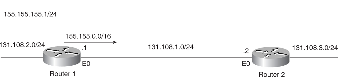
Figure 3-36 RIP Network Vulnerable to Autosummarization Problems
Example 3-98 shows that the subnetted route of 155.155.0.0/16 is missing from the routing table of R2, but the major network route is present. This means that R1 is advertising the routes but is somehow summarizing the subnets to go as 15.155.0.0/16.
Example 3-98 R2’s Routing Table Reflects That the Subnetted Route Is Missing
R2#show ip route 155.155.155.0 255.255.255.0
% Subnet not in table
R2#show ip route 155.155.0.0
Routing entry for 155.155.0.0/16
Known via "rip", distance 120, metric 1
Redistributing via rip
Advertised by rip (self originated)
Last update from 131.108.1.1 on Ethernet0, 00:00:01 ago
Routing Descriptor Blocks:
* 131.108.1.1, from 131.108.1.1, 00:00:01 ago, via Ethernet0
Route metric is 1, traffic share count is 1
Figure 3-37 shows the flowchart to fix this problem based on the autosummarization feature being enabled.

Figure 3-37 Flowchart to Solve Why the Sender Is Not Advertising RIP Routes
Debugs and Verification
Example 3-99 shows the configuration of R1 in the case of RIP-1. RIP-1 is a classful protocol and always summarizes to classful boundaries for nondirectly connected major networks.
Example 3-99 R1 Configuration with RIP Version 1
R1#
interface Loopback1
ip address 131.108.2.1 255.255.255.0
!
interface Loopback3
ip address 155.155.155.1 255.255.255.0
!
interface Ethernet0
ip address 131.108.1.1 255.255.255.0
!
router rip
network 131.108.0.0
network 155.155.0.0
Example 3-100 shows the routing table in Router R2. Notice that R2 is receiving 155.155.0.0/16, not 155.155.155.0/24, as configured on R1. Also note that R2 is receiving a /24 route of 131.108.2.0, the route of the same major network as that of interface Ethernet 0, which connects R1 to R2.
Example 3-100 R2 Routing Display to Show How Subnetted Routes Are Summarized to Classful Boundaries
R2#show ip route RIP
R 155.155.0.0/16 [120/1] via 131.108.1.1, 00:00:22, Ethernet0
131.108.0.0/24 is subnetted, 3 subnets
R 131.108.2.0 [120/1] via 131.108.1.1, 00:00:22, Ethernet0
Solution
In RIP-1, there is no workaround for this problem because RIP-1 is a classful routing protocol. RIP-1 automatically summarizes any update to a natural class boundary when that update goes over an interface configured with a different major network.
As indicated by R2’s routing table in Example 3-100, 155.155.155.0/24 is advertised over an interface configured with 131.108.0.0. This summarizes 155.155.155.0/24 to a Class B boundary as 155.155.0.0/16.
In RIP-1, this is not a problem because RIP-1 is a classful protocol and the network should be designed with this understanding. With RIP-2, however, Cisco routers can be configured to stop the autosummarization process.
For example, R1’s configurations can be changed to run a RIP-2 process rather than a RIP-1 process.
Example 3-101 shows the configuration that solves this problem for RIP-2.
Example 3-101 Disabling Autosummarization in RIP-2
router rip
version 2
network 131.108.0.0
network 155.155.0.0
no auto-summary
Example 3-102 shows the routing table of Router R2, which indicates that it is now receiving desired subnetted route 155.155.155.0/24.
Example 3-102 Router R2’s Routing Table Shows That It Is Receiving the Subnetted Route 155.155.155.0/24
R2#show ip route 155.155.0.0
155.155.0.0/24 is subnetted, 1 subnets
R 155.155.155.0 [120/1] via 131.108.1.1, 00:00:21, Ethernet0
131.108.0.0/24 is subnetted, 3 subnets
R 131.108.2.0 [120/1] via 131.108.1.1, 00:00:21, Ethernet0
Troubleshooting Routes Summarization in RIP
Route summarization refers to summarizing or reducing the number of routes in a routing table. For example, 131.108.1.0/24, 131.108.2.0/24 and 131.108.3.0/24 can be reduced to one route entry (that is, 131.108.0.0/16 or 131.108.0.0/22), the latter of which will cover only these three subnets. Route summarization (autosummarization and manual summarization, both of which are addressed in this section) is used to reduce the size of the routing table. This section discusses the most significant problem related to the route summarization—the RIP-2 routing table is huge. Two of the most common causes for this are as follows:
• Autosummarization is off.
• ip summary-address is not used.
Figure 3-38 shows a network setup that could produce a large routing table.

Figure 3-38 Network Setup That Could Generate a Large Routing Table
Problem: RIP-2 Routing Table Is Huge—Cause: Autosummarization Is Off
When a RIP update crosses a major network, it summarizes to the classful boundary. For example, 131.108.1.0, 131.108.2.0, and 131.108.3.0 will be autosummarized to 131.108.0.0/16 when advertised to a router with no 131.108.X.X addresses on its inter-faces. Disabling the autosummarization feature increases the size of the routing table. In some situations, this feature must be turned off (for example, if discontiguous networks exist, as discussed earlier).
Figure 3-39 shows the flowchart to follow to solve this problem based on this cause.

Figure 3-39 Flowchart to Resolve a Large RIP-2 Routing Table
Debugs and Verification
Example 3-103 shows the configuration on R2 that produces this problem. In this configuration, R2 has autosummary turned off.
Example 3-103 Disabling Autosummarization Under RIP for R2
R2#
router rip
version 2
network 132.108.0.0
network 131.108.0.0
no auto-summary
Example 3-104 shows R1’s routing table. This routing table has only four routes, but in a real network with the configuration in Example 3-103, there could be several hundred routes. R1 is receiving every subnet of 131.108.0.0/16. In this example, these are only three, but it can be much, much worse.
Example 3-104 Router R1 Routing Table Shows Subnetted Routes in the Routing Table
R1#show ip route rip
131.108.0.0/24 is subnetted, 3 subnets
R 131.108.3.0 [120/1] via 132.108.1.2, 00:00:24, Serial3
R 131.108.2.0 [120/1] via 132.108.1.2, 00:00:24, Serial3
R 131.108.1.0 [120/1] via 132.108.1.2, 00:00:24, Serial3
R1#
Solution
Because the autosummarization feature is disabled under the RIP configuration of R2, R1 sees the subnetted routes in the routing table. When this feature is enabled, all the subnetted routes will go away.
Example 3-105 shows the altered configuration of R2. In this configuration, autosummarization is on, to reduce the size of the routing table. Because this is the default, you will not see it in the configuration. The command to enable autosummarization is auto-summary under router rip.
Example 3-105 R2 Uses Autosummarization to Reduce Routing Table Size
R2#
router rip
version 2
network 132.108.0.0
network 131.108.0.0
Example 3-106 shows the reduced size of the routing table.
Example 3-106 Autosummary Reduces the Routing Table Size for Router R1
R1#show ip route rip
R 131.108.0.0/16 [120/1] via 132.108.1.2, 00:00:01, Serial3
R1#
Problem: RIP-2 Routing Table Is Huge—Cause: ip summary-address Is Not Used
Figure 3-40 shows the network setup that could produce a large routing table.

Figure 3-40 Network Setup That Could Generate a Large Routing Table
Figure 3-40 shows that R2 is announcing several subnets of 131.108.0.0 network. Notice that the link between R1 and R2 is also part of the 131.108.0.0 network, so autosummarization cannot play any role to solve the problem of receiving a subnet route that could be summarized. The autosummarization feature could have worked only if the R1, R2 link was in a different major network.
Figure 3-41 shows the flowchart to follow to solve this problem based on this cause.

Figure 3-41 Flowchart to Resolve a Large RIP-2 Routing Table
Debugs and Verification
Example 3-107 shows that in the configuration of R2, the ip summary-address command is not used under the Serial 1 interface to summarize the routes.
Example 3-107 R2’s Serial Interface Is Not Configured to Summarize Routes
R2#
interface Serial1
ip address 131.108.4.2 255.255.255.0
!
router rip
version 2
network 131.108.0.0
Example 3-108 shows the routing table of R1. In this example, there are only three routes. In a real network, however, the number could be worse based on the configuration in Example 3-107.
Example 3-108 R1 Routing Table Shows Subnetted Routes
R1#show ip route rip
131.108.0.0/24 is subnetted, 3 subnets
R 131.108.3.0 [120/1] via 131.108.4.2, 00:00:04, Serial3
R 131.108.2.0 [120/1] via 131.108.4.2, 00:00:04, Serial3
R 131.108.1.0 [120/1] via 131.108.4.2, 00:00:04, Serial3
R1#
Solution
In the situation described in the preceding section, autosummary is on but is not helpful because the whole network is within one major network. Imagine a network with Class B address space with thousands of subnets. Autosummary cannot play any role here because no major network boundary is crossed. A new feature of summarization was introduced in RIP starting with Cisco IOS Software Release 12.0.7T. This feature is similar to EIGRP manual summarization.
Example 3-109 shows the new configuration that solves this problem. This configuration reduces the size of the routing table. This command can be used with different masks so that, if a network has contiguous blocks of a subnet, the router could be configured to summarize subnets into smaller blocks. This then would reduce the routes advertised to the RIP network.
Example 3-109 Manual Summarization with RIP
R2#:
interface Serial1
ip address 131.108.4.2 255.255.255.0
ip summary-address rip 131.108.0.0 255.255.252.0
!
router rip
version 2
network 131.108.0.0
Based on the preceding configuration, R2 will summarize the RIP route on the Serial 1 interface. Any network subnet that falls in the 131.108.0.0 network will be summarized to one 131.108.0.0 major network, and its mask will be 255.255.252.0. This means that R2 will announce only a single summarize route of 131.108.0.0/22 and will suppress the subnets of 131.108.0.0.
Example 3-110 shows the routing table of Router R1 with a reduced number of entries as a result of summarization.
Example 3-110 R1’s Routing Table Is Reduced as a Result of Summarization
R1#show ip route rip
R 131.108.0.0/22 [120/1] via 131.108.4.2, 00:00:01, Serial3
R1#
Troubleshooting RIP Redistribution Problems
This section talks about problems that can happen during redistribution in RIP. Redistribution refers to the case when another routing protocol or a static route or connected route is being injected into RIP. Special care is required during this process to avoid any routing loops. In addition, metric (hop count) should be defined during this process, to avoid problems.
The most prevalent problem encountered with RIP redistribution is that redistributed routes are not being installed in the routing table of the RIP routers receiving these routes. When destination routes are not present in a routing table, no data can reach those destinations. The most common cause of this is a metric that is not defined during redistribution into RIP.
In RIP, the metric for a route is treated as a hop count that shows the number of routers that exist along this route. As discussed in Chapter 2, 15 is the maximum hop count that RIP supports; anything greater than 15 is treated as the infinite metric and, upon receipt, is dropped.
Figure 3-42 shows the network setup that could produce the problem in which redistributed routes do not get installed in the routing table of the receiver.

Figure 3-42 Network Vulnerable to Redistributed Route Problems
R1 and R3 are running OSPF in Area 0, whereas R1 and R2 are running RIP. R3 is announcing 131.108.6.0/24 through OSPF to R1. In R1, OSPF routes are being redistributed into RIP, but R2 is not receiving 131.108.6.0/24 through RIP.
Figure 3-43 shows the flowchart to follow to solve this problem based on this cause.

Figure 3-43 Flowchart to Resolve Redistributed Route Problems
Debugs and Verification
To troubleshoot this problem, you need to investigate whether R1 is receiving 131.108.6.0/24.
Example 3-111 shows that R3 is advertising 131.108.6.0/24 through OSPF to R1.
Example 3-111 show ip route Output Confirms That OSPF Is Working Fine and That R1 Is Receiving 131.108.6.0/24
R1#show ip route 131.108.6.0
Routing entry for 131.108.6.0/24
Known via "ospf 1", distance 110, metric 20, type intra area
R1 must be configured to redistribute OSPF routes in RIP. Example 3-112 shows that R1 is redistributing OSPF in RIP.
Example 3-112 Configuring R1 So That OSPF Is Redistributed in RIP
R1#
router rip
version 2
redistribute ospf 1
network 131.108.0.0
Now, you must first investigate R2 whether 131.108.6.0/24 is coming.
Example 3-113 shows that, in R2, 131.108.6.0/24 is not present in the RIP routing table.
Example 3-113 R2 Routing Table Does Not Reflect That 131.108.6.0/24 Is Present
R2#show ip route 131.108.6.0
% Subnet not in table
There are two basic ways to view this issue. The first is a simple show run on R1. The second is to run the debug ip rip on R2 command to watch the process.
Example 3-114 shows the output of debug ip rip.
Example 3-114 debug ip rip Output Shows That 131.108.6.0/24 Is Inaccessible
R2#debug ip rip
RIP: received v2 update from 131.108.1.1 on Ethernet1
131.108.6.0/24 -> 0.0.0.0 in 16 hops (inaccessible)
Solution
In RIP-1 or RIP-2, 16 is considered to be an infinite metric. Any update with a metric greater than 15 will not be considered for entry into the routing table.
In this example, the OSPF route in R1 for 131.108.6.0/24 has a metric of 20. When OSPF is redistributed into RIP in R1, OSPF advertised 131.108.6.0/24 with a metric of 20, which exceeds the maximum metric allowed in RIP. OSPF knows only cost as a metric, whereas RIP utilizes hop count. No metric translation facility exists, so the administrator must configure a metric to be assigned to redistributed routes.
Without the default metric configuration in R1, R2, upon receiving this update, complains about the excessive metric and marks it as (inaccessible), as shown in Example 3-114.
To correct this problem, R1 needs to assign a valid metric through configuration when doing the redistribution, as done for R1 in Example 3-115.
Example 3-115 Assigning a Valid Metric for Successful Redistribution
R1#
router rip
version 2
redistribute ospf 1 metric 1
network 131.108.0.0
In the configuration of Example 3-155, all redistributed routes from OSPF in RIP get a metric of 1. This metric is treated as hop count by R2.
Example 3-116 shows that R2 is receiving the correct route with a metric of 1.
Example 3-116 debug ip rip Reveals That the New Configuration for R1 Works and That R2 Is Receiving the Correct Route
R2#debug ip rip
RIP: received v2 update from 131.108.1.1 on Ethernet1
131.108.6.0/24 -> 0.0.0.0 in 1 hops
Example 3-117 shows that the route gets installed in the routing table of R2.
Example 3-117 R2 Routing Table Reflects That the Redistribution for Route 131.108.6.0/24 Is Successful
R2#show ip route 131.108.6.0
Routing entry for 131.108.6.0/24
Known via "rip", distance 120, metric 1
Troubleshooting Dial-on-Demand Routing Issues in RIP
Dial-on-demand routing (DDR) is common in scenarios in which the ISDN or similar dialup links are used as a backup link. When the primary link goes down, this backup link comes up. RIP begins sending and receiving updates on this link as long as the primary link is down.
The dialup links can be used as a backup for the primary link in two ways:
• Use the backup interface command.
• Use a floating static route with a dialer list that defines interesting traffic.
The first method is very simple: The command is typed under the dial interface, indicating that it’s a backup for a primary interface.
The second method requires a floating static route with a higher administrative distance than RIP (for example, 130 or above). It also requires defining interesting traffic that should bring up the link. The RIP broadcast address of 255.255.255.255 must be denied in the dialer list, so it shouldn’t bring up the link unnecessarily.
When running RIP under DDR situations, there are a number of issues to consider. Some problems are related to the ISDN line or an async line in which RIP updates keep bouncing. Some problems are related to the configuration. This section talks about the two most common dialup problems:
• A RIP broadcast is keeping the link up.
• RIP updates are not going across the dialer interface.
Problem: RIP Broadcast Is Keeping the ISDN Link Up—Cause: RIP Broadcasts Have Not Been Denied in the Interesting Traffic Definition
ISDN links are typically used as backup links when primary links go down. Cisco IOS Software requires that a router be instructed on which kind of traffic can bring up the ISDN link and keep it up. Such traffic is referred to as interesting traffic. Network operators typically want data traffic to be considered as interesting traffic to bring and keep the ISDN link up. RIP or other routing protocol updates should not be defined as interesting traffic. If this is not done, when the ISDN link comes up, it stays up as long as routing updates (RIP, in this case) are sent on a regular basis. That is not be the desired behavior because ISDN provides low-speed connectivity, and some data actually might go over the slow link even though the primary faster link is available.
Figure 3-44 shows the network setup that produces these particular DDR issues.

Figure 3-44 Network Setup Vulnerable to DDR Problems
Figure 3-45 shows the flowchart to follow to fix this problem.

Figure 3-45 Flowchart to Solve the RIP Broadcast Keeping the ISDN Link Up Problem
Debugs and Verification
Example 3-118 shows the configuration on Router R1 that produces this problem. In this configuration, only TCP traffic is denied. In other words, TCP traffic will not bring up and sustain the link. RIP broadcasts utilize UDP port 520. Because the permit ip any any command allows UDP port 520 to go through, RIP traffic is considered interesting traffic.
In Example 3-118, interface BRI 3/0 is configured to dial via the dialer-map command to the router with an IP address of 192.168.254.14 (R2). The number of dial is 57654. The dialer-group command defines dialer-list 1, which relies on access-list 100 to define the interesting traffic. In this example, access-list 100 denies all TCP traffic and permits all IP traffic. In other words, TCP traffic will not bring up and keep up the ISDN link, whereas other traffic, including RIP, can do so.
Example 3-118 Configuring the ISDN Interface with dialer-group to Define Interesting Traffic
R1#
interface BRI3/0
ip address 192.168.254.13 255.255.255.252
encapsulation ppp
dialer map ip 192.168.254.14 name R2 broadcast 57654
dialer-group 1
isdn switch-type basic-net3
ppp authentication chap
access-list 100 deny tcp any any
access-list 100 permit ip any any
dialer-list 1 protocol ip list 100
Example 3-119 shows the output of show dialer, which shows that the reason for the link coming up is a RIP broadcast.
Example 3-119 show dialer Output Reveals That a RIP Broadcast Is Keeping the ISDN Link Up
R1#show dialer
BRI1/1:1 - dialer type = ISDN
Idle timer (120 secs), Fast idle timer (20 secs)
Wait for carrier (30 secs), Re-enable (2 secs)
Dialer state is data link layer up
Dial reason: ip (s=192.168.254.13, d=255.255.255.255)
Current call connected 00:00:08
Connected to 57654 (R2)
In Example 3-119, Dial reason section 255.255.255.255 is the destination IP address, which is the address where RIP-1 advertisements will go on BRI1/1:1. Dial reason indicates that the interesting traffic is RIP, which has caused this ISDN to dial in the first place.
Solution
When running RIP and DDR, define an access list for interesting traffic. In Example 3-118, the access list is denying only the TCP traffic and permitting all the IP traffic. RIP uses an IP broadcast address of 255.255.255.255 to send the routing updates. This address must be denied in the access list so that RIP doesn’t bring up the link every 30 seconds. Denying 255.255.255.255 as a destination will block all broadcast traffic from bringing up the link. Blocking UDP port 520 will block RIP-1 and RIP-2 updates specifically. When the link is up, RIP can flow freely across the link. However, it will not keep the link up because it’s not part of the interesting traffic definition.
Example 3-120 shows the correct configuration change in Router R1. In this configuration, all traffic destined to 255.255.255.255 address is denied. This covers all broadcast traffic, so RIP-1 will not bring up the link after this configuration change.
Example 3-120 Correct Configuration for Router R1 in access -list 100 to Deny Traffic from the RIP-1 Broadcast IP Address
R1#
access-list 100 deny ip any 255.255.255.255
access-list 100 permit ip any any
dialer-list 1 protocol ip list 100
One important thing to know here is that RIP-1 uses the 255.255.255.255 address for sending RIP updates. RIP-2, on the other hand, uses 224.0.0.9. So, when dealing with RIP-2, you need to deny traffic from the multicast address of 224.0.0.9 as interesting traffic, as demonstrated in Example 1-21.
Example 3-121 Configuration for Router R1 in access-list 100 to Deny Traffic from the RIP-2 Broadcast IP Address
R1#
access-list 100 deny ip any 224.0.0.9
access-list 100 permit ip any any
Also, in a situation in which both RIP-1 and RIP-2 are running, both of these broadcast addresses should be denied in the access list, as demonstrated in Example 3-122.
Example 3-122 Configuration for Router R1 in access-list 100 to Deny Traffic from the RIP-1 and RIP-2 Broadcast IP Addresses
access-list 100 deny ip any 255.255.255.255
access-list 100 deny ip any 224.0.0.9
access-list 100 permit ip any any
Because both RIP-1 and RIP-2 use UDP port 520, it would be most efficient to deny this port if RIP-1 and RIP-2 are not considered interesting traffic. Example 3-123 demonstrates this.
Example 3-123 Configuring access-list 100 for R1 to Deny Traffic from the RIP-1 and RIP-2 UDP Port
R1#
access-list 100 deny udp any any eq 520
access-list 100 permit ip any any
The final configuration of R1 would like Example 3-124.
Example 3-124 Efficient Configuration of R1 when RIP-1 and RIP-2 Are Both Denied as Interesting Traffic
R1#
interface BRI3/0
ip address 192.168.254.13 255.255.255.252
encapsulation ppp
dialer map ip 192.168.254.14 name R2 broadcast 57654
dialer-group 1
isdn switch-type basic-net3
ppp authentication chap
!
access-list 100 deny udp any any eq 520
access-list 100 permit ip any any
!
dialer-list 1 protocol ip list 100
Problem: RIP Updates Are Not Going Across the Dialer Interface—Cause: Missing broadcast Keyword in a dialer map Statement
When a dialer interface (ISDN, for example) comes up, you might want to run a routing protocol over this link. Static routes might do the job, but in networks with a large number of routes, static routes might not scale. Therefore, running a dynamic routing protocol such as RIP is necessary. In some situations, the ISDN link might be up, but no routing information is going across. Without a routing protocol, no destination addresses can be learned and no traffic can be sent to those destinations. This problem must be fixed because the ISDN interface is of no use when it is not carrying any traffic.
Figure 3-46 shows the flowchart to follow to solve this problem based on this cause.

Figure 3-46 Flowchart to Solve the RIP Updates Not Going Across the Dialer Interface Problem
Debugs and Verification
Example 3-125 shows the configuration on R1 that produces this problem.
Example 3-125 Configuring R1 When No Routing Updates Will Go on the ISDN Link
R1#
interface BRI3/0
ip address 192.168.254.13 255.255.255.252
encapsulation ppp
dialer map ip 192.168.254.14 name R2 57654
dialer-group 1
isdn switch-type basic-net3
ppp authentication chap
Example 3-126 shows that RIP is sending the broadcast update toward R2. You can see that it’s failing because of the encapsulation failed message. Also in Example 3-126, R1 is running a debug ip packet command with access-list 100 to display only the UDP port 520 output. RIP-1 and RIP-2 use UDP port 520 to exchange updates with other RIP running routers.
Example 3-126 Discovering Why RIP Routes Are Not Going Across an ISDN Interface
R1#
access-list 100 permit udp any any eq 520
access-list 100 deny ip any any
R1#debug ip packet 100 detail
IP: s=192.168.254.13 (local), d=255.255.255.255 (BRI3/0), len 46, sending
broad/multicast
UDP src=520, dst=520
IP: s=192.168.254.13 (local), d=255.255.255.255 (BRI3/0), len 72, encapsulation
failed
UDP src=520, dst=520
Solution
The root of the issue is RIP’s use of broadcasts to send its routing updates. In DDR, dialer map statements are necessary to associate the next-hop protocol address to the phone number dialed to get to the destination. The broadcast keyword must be used in the dialer map statements; otherwise, the broadcast will encounter the encapsulation failure message demonstrated by Example 3-126. To correct this problem, add the broadcast keyword in the dialer map statement, as demonstrated in Example 3-127 for Router R1.
Example 3-127 Corrected Configuration of R1 to Enable RIP Updates to Go Across the ISDN Interface
interface BRI3/0
ip address 192.168.254.13 255.255.255.252
encapsulation ppp
dialer map ip 192.168.254.14 name R2 broadcast 57654
dialer-group 1
isdn switch-type basic-net3
ppp authentication chap
Troubleshooting Routes Flapping Problem in RIP
Running RIP in a complex environment can sometimes cause flapping of routes. Route flapping refers to routes coming into and going out of the routing table. To check whether the routes are indeed flapping, check the routing table and look at the age of the routes. If the ages are constantly getting reset to 00:00:00, this means that the routes are flapping. Several reasons exist for this condition. This section discusses one of the common reasons—packet loss because the packet is dropping on the sender’s or receiver’s interface. The example in this section considers Frame Relay because it is the most common medium in which this problem occurs. The packet loss can be verified through the interface statistics by looking at the number of packet drops and determining whether that number is constantly incrementing.
Figure 3-47 shows the network setup that can produce RIP route flapping.

Figure 3-47 Network Vulnerable to RIP Route Flapping
Figure 3-48 shows the flowchart to follow to solve this problem.

Figure 3-48 Flowchart to Solving the RIP Route Flapping Problem
Debugs and Verification
In a large RIP network, especially, in a Frame Relay environment, there is a high possibility that RIP updates are lost in the Frame Relay cloud or that the RIP interface dropped the update. Again, the symptoms can be present in any Layer 2 media, but Frame Relay is the focus here. This situation causes RIP to lose a route for a while. If RIP does not receive a route for 180 seconds, the route is put in a holddown for 240 seconds and then is purged. This situation is corrected by itself (and time), but, in some cases, configuration changes can be required. For example, consider the output in Example 3-128, where no RIP update has been received for 2 minutes and 8 seconds. This means that four RIP updates have been missed, and we are 8 seconds into the fifth update.
Example 3-128 Routing Table of the Hub Router Showing That the Last RIP Update Was Received 2:08 Minutes Ago
Hub#show ip route rip
R 155.155.0.0/16 [120/1] via 131.108.1.1, 00:02:08, Serial0
R 166.166.0.0/16 [120/1] via 131.108.1.1, 00:02:08, Serial0
Example 3-129 shows that there are a large number of broadcast drops on the interface.
Example 3-129 show interfaces serial 0 Output Reveals a Large Number of Broadcast Drops
Hub#show interfaces serial 0
Serial0 is up, line protocol is up
Hardware is MK5025
Description: Charlotte Frame Relay Port DLCI 100
MTU 1500 bytes, BW 1024 Kbit, DLY 20000 usec, rely 255/255, load 44/255
Encapsulation FRAME-RELAY, loopback not set, keepalive set (10 sec)
LMI enq sent 7940, LMI stat recvd 7937, LMI upd recvd 0, DTE LMI up
LMI enq recvd 0, LMI stat sent 0, LMI upd sent 0
LMI DLCI 1023 LMI type is CISCO frame relay DTE
Broadcast queue 64/64, broadcasts sent/dropped 1769202/1849660, interface
broadcasts 3579215
Solution
The show interfaces serial 0 command further proves that there is some problem at the interface level. Too many drops are occurring at the interface level. This is the cause of the route flapping. In the case of Frame Relay, the Frame Relay broadcast queue must be tuned. Tuning the Frame Relay broadcast queue is out of the scope of this book; several papers at Cisco’s Web site discuss how to tune the Frame Relay broadcast queue.
In a non-Frame Relay situation, the input or output hold queue might need to be increased.
Example 3-130 shows that after fixing the interface drop problem, route flapping disappears.
Example 3-130 Serial Interface Output After Adjusting the Broadcast Queue
Hub#show interfaces serial 0
Serial0 is up, line protocol is up
Hardware is MK5025
Description: Charlotte Frame Relay Port DLCI 100
MTU 1500 bytes, BW 1024 Kbit, DLY 20000 usec, rely 255/255, load 44/255
Encapsulation FRAME-RELAY, loopback not set, keepalive set (10 sec)
LMI enq sent 7940, LMI stat recvd 7937, LMI upd recvd 0, DTE LMI up
LMI enq recvd 0, LMI stat sent 0, LMI upd sent 0
LMI DLCI 1023 LMI type is CISCO frame relay DTE
Broadcast queue 0/256, broadcasts sent/dropped 1769202/0, interface broadcasts
3579215
In Example 3-131, the show ip routes output displays that the routes are stable in the routing table and that the timers are at a value lower than 30 seconds.
Example 3-131 show ip routes Output Reveals Stable RIP Routes
Hub#show ip route rip
R 155.155.0.0/16 [120/1] via 131.108.1.1, 00:00:07, Serial0
R 166.166.0.0/16 [120/1] via 131.108.1.1, 00:00:07, Serial0