Chapter 2. Understanding Routing Information Protocol (RIP)
This chapter covers the following key topics about Routing Information Protocol (RIP):
• Metric
• Timers
• Split horizon with poison reverse
• Why RIP doesn’t support discontiguous networks
• Why RIP doesn’t support variable-length subnet masking (VLSM)
RIP is a distance vector protocol that uses hop count as its metric. This protocol is very simple and was intended for small networks. RIP is similar to gated, which was distributed by the FreeBSD version of UNIX. Before the RFC for RIP Version 1 (RIP-1) was written, several versions of RIP were floating around.
Note
Hop count refers to the number of routers being traversed. For example, a hop count of 2 means that the destination is two routers away.
RIP is a classful protocol, which means that it doesn’t carry subnet mask information in its routing update. Because it doesn’t carry any subnet mask information, it is incapable of supporting variable-length subnet masking (VLSM) and discontiguous networks. RIP enables devices to exchange information about networks that they are directly connected to, as well as any other networks that they have learned from other RIP devices.
RIP sends its routing information every 30 seconds, which is the default update timer. This timer is configurable. The hold-down timer determines how long a router should wait before flushing the information from the routing table.
RFC 1058 was written to provide a standard for RIP, which uses the Bellman-Ford algorithm to compute its metric.
Metric
The RIP metric is based on hop count and can be between 1 and 15. The metric 16 is used for infinity, which means that if the route is unreachable, a metric of 16 is displayed. The question is, why was the metric chosen as 16? Why not 17 or 18? The metric filed in RIP-1 packet format clearly shows that it is 32 bits long. This means that, theoretically, RIP can support 232 hops. Although this is a large number, the metric of 15 was chosen to avoid a count to infinity problem. (This is also referred to as a routing loop.) In a large network with a few hundred routers, a routing loop results in a long time for convergence if the metric for infinity has a large value. The number 16 was chosen to get a shorter convergence time.
The 15-hop limit was chosen also because RIP was intentionally designed for small networks. It was not intended for the large networks that potentially can have more than 15 hops.
Timers
Like any distance vector protocol, RIP periodically sends an update every 30 seconds. This update consists of a broadcast of the entire routing table. The update timer controls this 30-second period. RIP uses the following timers:
• Update—The time between each update interval. This value is set to 30 seconds, by default, and is configurable.
• Invalid—The time after which a suspect route becomes invalid. This is set to 180 seconds, by default.
• Hold-down—The time used to suppress the possibility of defective routes being installed in the routing table. The default time is 180 seconds.
• Flush—The time after which a route is removed from the routing table. This is set to 240 seconds, by default.
Split Horizon
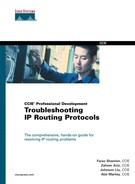
Split horizon is a technique used to avoid routing loops. With split horizon, when a route is learned on an interface, that route is not advertised back out on the same interface. For example, in Figure 2-1, Router 1 receives an update about Network X with a metric of 1 from the neighboring Router 2. Router 1 will not advertise Network X back to Router 2 if split horizon is enabled. If split horizon is disabled, however, Router 1 will advertise Network X with a metric of 2 to Router 2. If Network X fails, Router 2 will think that Router 1 has a better way to get to X, so it will send the packet destined to Network X toward Router 1, creating a black hole.
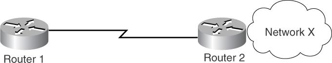
Figure 2-1 An Example of Split Horizon
Split Horizon with Poison Reverse
Another technique used to avoid routing loops is split horizon with poison reverse. With this technique, routes learned on an interface are advertised back on the same interface, but they are poisoned, which means that they have a metric of 16 (unreachable). In Figure 2-1, Router 1 receives an update about Network X with a metric of 1 from neighboring Router 2. In the case of split horizon with poison reverse, Router 1 will advertise Network X back to Router 2, but with a metric of 16, which indicates infinity.
Split horizon with poison reverse is used only when a link failure occurs. It also can be used in a normal situation, but it is discouraged because it can potentially increase the size of the routing table.
RIP-1 Packet Format
The maximum datagram size in RIP is 512 octets. The first byte is used for commands such as rip update request and rip update response. The next byte is used for the Version field, which is set to 1 for RIP-1. The next 2 bytes must be 0. The 2-byte field after this is used for the address family identifier; the next 14 bytes are allocated for the network address, as shown in Figure 2-2. In the case of IP, only 4 bytes of those 14 are used for the IP address. The remaining 10 bytes are unused in RIP-1, although they are used in the RIP Version 2 (RIP-2) packet format. The next 4 bytes are used for the RIP metric, which can be up to 16. The portion from the address family identifier up to the Metric field can be repeated 25 times, to yield the maximum RIP packet size of 512 bytes.

Figure 2-2 RIP-1 Packet Format
RIP Behavior
RIP follows certain rules when it sends and receives updates. This section covers the rules for sending and receiving updates.
RIP Rules for Sending Updates
When RIP sends an update, it performs several checks. In Figure 2-3, two routers are running RIP together. Router 1 is connected to two majornets, 131.108.0.0/16 and 137.99.0.0/16. The majornet 131.108.0.0 is further divided into two subnets: 131.108.5.0/24 and 131.108.2.0/24, which is actually connected to Router 2.
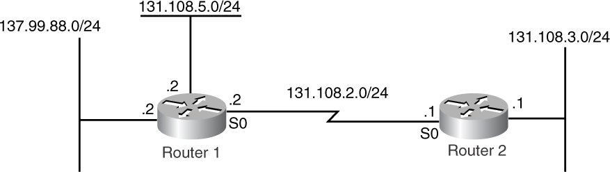
Figure 2-3 Example of RIP Behavior
Before Router 1 sends a RIP update to Router 2, it performs the check as shown in Figure 2-4.
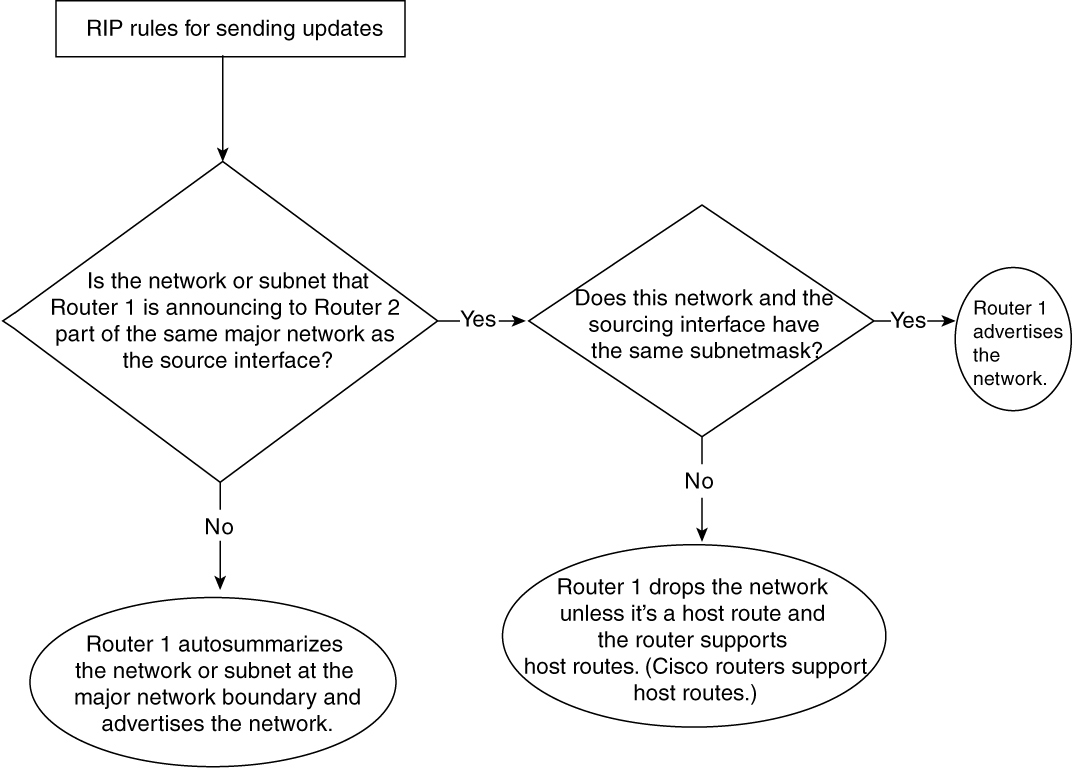
Figure 2-4 Flowchart That Explains RIP Rules When Sending Updates
When RIP sends the update, it checks to see whether the advertised network or subnet is on the same major network as the interface that is sourcing the RIP packet. If the advertised network or subnet is on a different major network from the interface sourcing the RIP packet, the network is autosummarized. In other words, RIP sends only the majornet information in its routing update. For example, in Figure 2-3, when Router 1 sends the RIP update to Router 2, it autosummarizes the subnet 137.99.88.0 into 137.99.0.0. If the advertised network or subnet is on the same major network as the router’s interface sourcing the RIP packet, RIP determines whether the advertised subnet has the same mask as the interface that is sourcing the RIP update. If it has the same mask, RIP advertises that network; otherwise, RIP drops that network.
RIP Rules for Receiving Updates
When the receiving side gets an update from RIP, the update can contain either a subnet number, a host address, a network number, or all 0s (indicating the default route):
• Subnet number (such as 131.108.1.0)
• Host address (such as 131.108.1.1)
• Network number (such as 131.108.0.0)
• Default route (such as 0.0.0.0)
Figure 2-5 illustrates the checks performed by RIP on the receiving side.
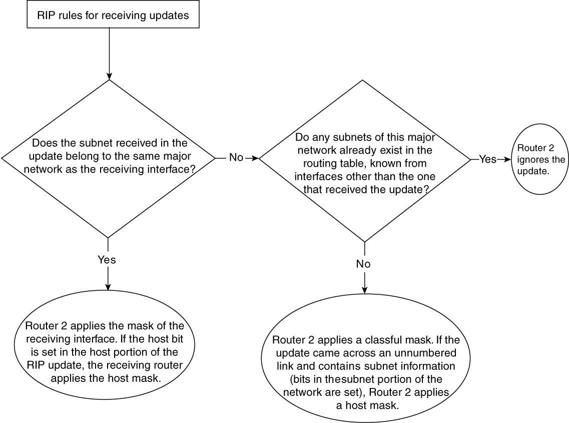
Figure 2-5 Flowchart That Explains RIP Rules When Receiving Updates
When RIP receives the update, it determines whether the subnet received in the update belongs to the same major network as the receiving interface. If so, Router 2 applies the mask of the receiving interface. If the host bits are set in the host portion of the RIP update, the receiving router applies the host mask.
If that subnet belongs to a different major network, RIP checks whether any subnets of this major network already exist in the routing table and determines whether they are known from interfaces other than the one that received the update. Note that the network in this update should be a major network. If the answer is “yes,” Router 2 ignores the update. If the answer is “no,” Router 2 applies a classful mask.
If the update came across an unnumbered link, it might contain subnet information (bits in the subnet portion of the network address are set). Router 2 then applies a host mask. If the update carries subnet broadcast—for example, 131.108.5.127/25 or Class D or E—the RIP update must be ignored.
Example of Sending Updates
This section shows an example explaining RIP behavior when it sends an update. In Figure 2-6, two routers are running RIP. The link between Router 1 and Router 2 is in 131.108.0.0. The Ethernet interface on Router 1 is in 131.108.0.0 as well. Router 1 is also connected to another major network, which is 137.99.0.0.

Figure 2-6 An Example of RIP Behavior When Sending and Receiving Updates
In Figure 2-6, when Router 1 sends an update to Router 2, it performs these checks:
1 Is 131.108.5.0/24 part of the same major network as 131.108.2.0/24, which is sourcing the update?
2 Yes. Does 131.108.5.0/24 have the same subnet mask 131.108.2.0/24, which is sourcing the update?
3 Yes. Router 1 advertises the network.
4 Is 137.99.88.0/24 part of the same major network as 131.108.2.0/24, which is sourcing the update?
5 No. Router 1 summarizes 137.99.88.0/24 at the major network boundary and advertises the route as 137.99.0.0.
This process results in Router 1 including 131.108.5.0 and 137.99.0.0 in its update to Router 2. You can see this in the output displayed using the debug ip rip command on Router 1, as demonstrated in Example 2-1.
Example 2-1 debug ip rip Command Output Reveals RIP Update Information Sent
Router1#debug ip rip
RIP: sending v1 update to 255.255.255.255 via Serial0 (131.108.2.2)
subnet 131.108.5.0, metric 1
network 137.99.0.0, metric 1
Example of Receiving Updates
Example 2-2 provides output from the debug ip rip command to display the routing update received on Router 2 from Router 1.
Example 2-2 debug ip rip Command Output Reveals RIP Update Information Received
Router2#debug ip rip
RIP: received v1 update from 131.108.2.2 on Serial0
131.108.5.0 in 1 hops
137.99.0.0 in 1 hops
Router 2 in Figure 2-6 performs the following checks to determine what mask to apply on a received network:
1 Is the received major network 137.99.0.0 the same as 131.108.2.0, which is the address assigned to the interface that received the update?
2 No. Do any subnets of this major network already exist in the routing table known from other interfaces?
3 No. Router 2 applies the natural mask (/16) because 137.99.0.0 is a Class B address.
4 Does subnet 131.108.5.0 belong to the same major network as subnet 131.108.2.0, which is the interface that received the update?
5 Yes. Router 2 applies the mask /24, which is the mask of the interface that received the update.
This process results in the networks and masks in Router 2’s routing table, displayed using the show ip route command (see Example 2-3).
Example 2-3 show ip route Command Output Reveals the Networks and Masks in Router 2’s Routing Table
Router2#show ip route
R 137.99.0.0/16 [120/1] via 131.108.2.2, 00:00:07, Serial0
131.108.0.0/24 is subnetted, 3 subnets
R 131.108.5.0 [120/1] via 131.108.2.2, 00:00:08, Serial0
C 131.108.2.0 is directly connected, Serial0
C 131.108.3.0 is directly connected, Ethernet0
Why RIP Doesn’t Support Discontiguous Networks
A discontiguous network is comprised of a major network separated by another major network. In Figure 2-7, network 131.108.0.0 is separated by a subnet of network 137.99.0.0; here, 131.108.0.0 is a discontiguous network.

Figure 2-7 An Example of a Discontiguous Network
RIP is a classful protocol. Whenever RIP advertises a network across a different major network boundary, RIP summarizes the advertised network at the major network boundary. In Figure 2-7, when Router 1 sends an update containing 131.108.5.0 to Router 2 across 137.99.88.0, it converts 131.108.5.0/24 into 131.108.0.0/16. This process is called autosummarization.
Router 1 takes the following steps before sending an update to Router 2:
1 Is 131.108.5.0/24 part of the same major network as 137.99.88.0/24, which is the subnet assigned to the interface that’s sourcing the update?
2 No. Router 1 summarizes 131.108.5.0/24 and advertises the route 131.108.0.0/16.
The debug ip rip command output on Router 1 shows the update sent by Router 1, as demonstrated in Example 2-4.
Example 2-4 debug ip rip Command Output Reveals RIP Update Information Sent by Router 1 in Figure 2-7
Router1#debug ip rip
RIP: sending v1 update to 255.255.255.255 via Serial0 (137.99.88.2)
network 131.108.0.0, metric 1
Router 2 goes through the following steps before accepting the update from Router 1:
1 Is the major network received (131.108.0.0) the same as the major network of 137.99.88.0/24, which is the subnet assigned to the interface that received the update?
2 No. Do any subnets of this major network already exist in the routing table known from interfaces other than that which received the update?
3 Yes. Router 2 ignores the update.
Again, debug ip rip command output on Router 2 shows the update received by Router 2, as demonstrated in Example 2-5.
Example 2-5 debug ip rip Command Output Reveals RIP Update Information Received by Router 2 in Figure 2-7
Router2#debug ip rip
RIP: received v1 update from 137.99.88.1 on Serial0
131.108.0.0 in 1 hops
The routing table of Router 2, as demonstrated in the show ip route command output in Example 2-6, shows that the update was ignored. The only entry for any subnetwork or network on 131.108.0.0 is the one directly connected to Ethernet0.
Example 2-6 show ip route Command Output Reveals That the Routing Table for Router 2 in Figure 2-7 Does Not Reflect the Advertised Route Sent by Router 1
137.99.0.0/24 is subnetted, 1 subnets
C 137.99.88.0 is directly connected, Serial0
131.108.0.0/24 is subnetted, 3 subnets
C 131.108.2.0 is directly connected, Ethernet0
To avoid having updates ignored, configure a static route on both routers that points toward the specific subnets. For example, on Router 1, configure the following:
Router1(config)#ip route 131.108.2.0 255.255.255.0 137.99.88.1
On Router 2, configure the following:
Router2(config)#ip route 131.108.5.0 255.255.255.0 137.99.88.2
Why RIP Doesn’t Support Variable-Length Subnet Masking
The capability to specify a different subnet mask for the same network number is called variable-length subnet masking (VLSM). RIP and IGRP are classful protocols and are incapable of carrying subnet mask information in their updates. Before RIP or IGRP sends an update, it performs a check against the subnet mask of the network that is about to be advertised, with the subnet mask of the interface sourcing the update. If the two subnet masks don’t match, the update gets dropped.
The following example demonstrates this concept. In Figure 2-8, Router 1 has three subnets with two different masks (/24 and /30).
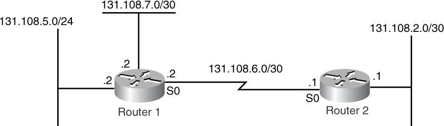
Figure 2-8 An Example of a VLSM Network
Router 1 goes through the following steps before sending an update to Router 2:
1 Router 1 checks to see if 131.108.5.0/24 is part of the same major network as 131.108.6.0/30, which is the network assigned to the interface that is sourcing the update.
2 It is part of the same major network, so Router 1 determines whether 131.108.5.0/24 has the same subnet mask as 131.108.6.0/30.
3 Because the subnet masks are not the same, Router 1 drops the network and doesn’t advertise the route.
4 Router 1 now determines whether 131.108.7.0/30 is part of the same major network as 131.108.6.0/30, which is the network assigned to the interface that is sourcing the update.
5 It is part of the same major network, so Router 1 next determines whether 131.108.7.0/30 has the same subnet mask as 131.108.6.0/30.
6 Because the two subnet masks are the same, Router 1 advertises the network.
The preceding procedure determined that Router 1 includes only 131.108.7.0 in its update that is sent to Router 2. The debug ip rip command in Example 2-7 actually shows the update sent by Router 1.
Example 2-7 debug ip rip Command Output Reveals RIP Update Information Sent by Router 1 to Router 2, as Illustrated in Figure 2-8
RIP: sending v1 update to 255.255.255.255 via Serial0 (131.108.6.2)
subnet 131.108.7.0, metric 1
Notice in the output in Example 2-7 that the only subnet included in the update is 131.108.7.0. The subnet 131.108.5.0 is not included because it has a different subnet mask. This results in the following entry in Router 2’s routing table displayed by the show ip route command (see Example 2-8).
Example 2-8 show ip route Command Output Reveals That the Subnet 131.108.5.0/25 Is Missing from Router 2’s Routing Table
Router2#show ip route
131.108.0.0/30 is subnetted, 3 subnets
R 131.108.7.0 [120/1] via 131.108.2.2, 00:00:08, Serial0
C 131.108.6.0 is directly connected, Serial0
C 131.108.2.0 is directly connected, Ethernet0
To avoid eliminating subnets from routing updates, either use the same subnet mask over the entire RIP network or use static routes for networks with different subnet masks.
Default Routes and RIP
Cisco’s RIP implementation supports the propagation of a default route, also known as 0.0.0.0/0. When RIP finds a default route in its routing table, it automatically advertises this in the RIP update.
One important thing to remember here is that the default route must have a valid metric. For example, if the default route is learned through OSPF and the metric is 20, RIP will advertise this router with a metric of infinity (16). So, for this situation, the default-metric command must be used under the router rip command to ensure that the proper metric is assigned to the update.
Classless and classful IP routing concepts play an important role, especially with default routes. With classful IP routing, if the router receives a packet destined for a subnet that it does not recognize and the network default route is missing in the routing table, the router discards the packet. Figure 2-9 explains this behavior.

Figure 2-9 Classful IP Routing
Here, Host X is sending traffic to the 131.108.3.0/24 subnet. Router R1 will discard these packets because it does not have a route for 131.108.3.0/24. Traffic will not be send to the default route because of the classful nature of routing.
If R1 enables IP classless routing, R1 will forward traffic to the default route.
Enabling IP classless routing is recommended when default network or default routes are used.
Protocol Extension to RIP
RIP Version 2 (RIP-2) made some improvements and enhancements to RIP-1. RIP-2 supports VLSM and discontiguous networks, and it offers the following enhancements:
Figure 2-10 shows the RIP-2 packet format. The sections that follow discuss each of the enhancements and new packet fields in greater detail.

Figure 2-10 RIP-2 Packet Format
Route Tag
The Route Tag field is a 2-byte field that allows RIP routes to be assigned with a unique integer value. The routing table display shows the route tag for each RIP route, if assigned. This route tag plays an important role during redistribution with RIP. Any route that is redistributed into RIP gets tagged, to distinguish between internal RIP information and external RIP information.
When redistributed routes in RIP are assigned with route tags, it becomes easier to control redistribution of tagged routes into other protocols. Instead of matching against each route when redistributing into other protocols, RIP routes can simply be matched against the tag that they were assigned.
For example, consider that 10 static routes in a router are redistributed in RIP and are assigned a tag of 20. These static routes will be advertised in RIP as external routes with a tag of 20. If in some other router RIP is being redistributed into OSPF and OSPF wants only those 10 static routes to be redistributed, OSPF can simply match the tag information instead of listing each static route in its redistribution commands. In addition, if OSPF is being redistributed back into RIP at some other router, RIP should deny any routes that are tagged with 20. Matching against tags thus avoids IP routing loops as well.
Subnet Mask
Unlike RIP-1, RIP-2 carries subnet mask information along with the IP network number. If an IP network is variably subnetted, RIP-2 picks the subnet mask of each subnet and advertises to RIP-2 neighbors. RIP-2 routers in the network install routes with their respective subnets though a variable length of, say, /8, /15/, /24, and so on.
Support of VLSM also enables RIP-2 to understand discontiguous networks. In a discontiguous network, the IP supernet is divided by another IP block. Because RIP-2 can carry subnet mask information, each RIP-2 router has a route with the actual mask and routers can forward traffic properly.
Next Hop
The Next Hop field was added to avoid an extra hop during packet forwarding. For those familiar with OSPF, the Next Hop field holds nearly the same role as the forwarding address for OSPF external routes.
In Figure 2-11, OSPF is enabled between Router 2 and Router 5. RIP is enabled on Router 2, Router 3, and all the other routers behind Router 2 and Router 3. Router 2 is doing redistribution between OSPF and RIP. Now when a packet from Router 1 is destined for OSPF networks and arrives at Router 2, it is forwarded to Router 5.

Figure 2-11 RIP-2 Packet Format
When a packet from Router 4 destined to the OSPF network arrives at Router 3, if there is no next-hop information (in case of RIP-1), Router 3 forwards the packet to the originator, Router 2. Then Router 2 forwards it to Router 5. This is an extra hop that Router 3 must take to get to the OSPF network. With the Next Hop field in the RIP packet, when a packet destined to the OSPF network arrives at Router 3, the RIP route for the destination network has its next hop set to Router 5 instead of Router 2. As a result, Router 3 does not forward the packet to Router 2—instead, it forwards the packet straight to Router 5.
Multicast Capability
RIP-2 uses multicast when sending an update to all its neighbors. This reduces unnecessary broadcast flooding on the wire. The multicast address that RIP-2 uses is 224.0.0.9.
All devices on the wire running RIP-2 listen for RIP-2 multicast packets on 224.0.0.9 at a multicast MAC address (01-00-5E-00-00-09). Devices not running RIP-2 simply discard RIP-2 messages on the wire, reducing unnecessary load.
Authentication
RIP-2 supports simple password authentication, to validate trusted RIP-2 neighbors. RIP-2 speakers determine whether authentication is used by looking at the address family identifier (AFI) in RIP-2 packet. AFI in RIP-2 header indicates what kind of addresses are present in the rest of the packet.
If the AFI value is 0xFFFF, this means that the remainder of the entire RIP packet contains authentication information.
Figure 2-12 shows the packet format when authentication is used.

Figure 2-12 RIP-2 Packet Format for Authentication
Compatibility Issues
RIP-1 and RIP-2 can be run together in a network. You should be aware of a few things when running both protocols in your network:
• Autosummarization—RIP-1 and RIP-2 can be run together in a network. RFC 1723 for RIP-2 recommends disabling the autosummarization feature when using both RIP-1 and RIP-2.
• Subnet advertisement—If a more specific subnet is advertised to a RIP-1 router, the router might mistakenly take it as a host route update.
• Queries—When a RIP-2 router receives a query request from a RIP-1 router, it responds with a RIP-1 message. If the router is configured to send only RIP-2 messages, such a query request must be ignored.
• Version field—The Version field in the RIP packet determines how to handle RIP-1 and RIP-2 packets:
— If version = 0 in the RIP packet, the packet is discarded, regardless of what version the receiving router is running.
— If version = 1 in the RIP packet, all the “must be zero fields” are checked (refer to Figure 2-9). If the version is nonzero, the packet is discarded, regardless of what version the receiving router is running.
— If version = 2 in the RIP packet and the receiving router is running RIP-1, the receiving router should look at only the related information in the packet. All the “must be zero fields” are ignored.
Summary
RIP is a distance vector protocol that uses the Bellman-Ford algorithm to compute IP routes dynamically. RIP is suitable to run in small IP networks because of its hop count limit of 15. RIP was designed as a simple IP routing protocol that exchanges a complete routing table at a fixed interval (30 seconds) with other routers running RIP. In larger networks with a large number of IP routes, sending a complete routing table every 30 seconds is not practical. This results in extra work for the sender and receiver, and it consumes unnecessary bandwidth and processing time. Therefore, RIP is used in smaller networks with a hop count of less than 15 and a small number of routes as well.
RIP offers a descent algorithm for loop avoidance by using split horizon and poison reverse. Split horizon takes care of the loops by not advertising any routes back to the interface where it learned the routes. Poison reverse causes routes to be advertised with the infinite RIP metric (16), thus removing RIP routes that might be looped or down.
Because any change in the network takes at least 30 seconds to propagate, the concept of holddown causes the RIP routing table to wait for three times the advertisement interval. This implementation is designed for when a RIP route is not advertised because it might have been down for a little over 30 seconds. The receiving routers should wait for 90 seconds to remove the route from the routing table. If a routes comes back before 90 seconds, it is reinstalled and is advertised throughout the network.
In the early days of IP networking, RIP was the protocol of choice in smaller IP networks. Since then, a lot of new IP protocols have been developed to be more robust and dynamic than RIP; they can scale up to a much larger number of routers than 15. The advent of these new protocols, such as OSPF, IS-IS, and EIGRP, resulted in almost complete phaseout of RIP from larger networks today. These new protocols have improved upon the limitations of RIP in terms of convergence and scalability, and they offer the support for VLSM and discontiguous networks that RIP-1 lacked.
Although RIP-2 improved RIP with new features, such as route tags, queries, subnet masks, next hops, multicasting, and authentication, larger networks still prefer OSPF, IS-IS, and EIGRP as IP routing protocols.
Review Questions
1 What is the maximum metric in RIP?
2 Why doesn’t RIP support discontiguous networks?
3 Why doesn’t RIP support VLSM?
4 What is the default update interval for RIP?
5 What transport protocol and port number do RIP use for sending updates?
6 What is the purpose of the split-horizon technique?
7 Does RIP Version 2 solve the discontiguous network problem by default?
8 Does RIP Version 2 also use broadcast for sending updates?
9 Does RIP support authentication?
Further Reading
Refer to the following RFCs for more information about RIP. You can access all RFCs online at www.isi.edu/in-notes/rfcxxxx.txt, where xxxx is the number of the RFC that you want to read.
RFC 1058, “Routing Information Protocol”
RFC 1723, “RIP Version 2”
RFC 2453, “RIP Version 2”
RFC 1582, “Extensions to RIP to Support Demand Circuits”
RFC 2091, “Triggered Extensions to RIP to Support Demand Circuits”
RFC 2082, “RIP-2 MD5 Authentication”