
Chapter 5. Troubleshooting IGRP
This chapter covers the following key topics:
• Troubleshooting IGRP route installation
• Troubleshooting IGRP route advertisement
• Troubleshooting IGRP redistribution problems
• Troubleshooting dial-on-demand (DDR) routing issues in IGRP
• Troubleshooting route flapping in IGRP
• Troubleshooting variance problem
This chapter discusses common problems in IGRP networks and how to solve those problems. IGRP is a Cisco proprietary protocol. IGRP fixes some of the problems with RIP, but still it has similar characteristics as RIP. IGRP also does not support discontiguous networks or VLSM; however, it does have good features, such as variance, and its metric is based on bandwidth and delay instead of hop count.
Most of the issues in IGRP are very similar to RIP, so those issues are repeated here again in this chapter from an IGRP perspective. As mentioned in Chapter 3, “Troubleshooting RIP,” you must be careful with the debugs when dealing with large networks (for example, more than 100 subnets in a network) because debugging sometimes can have an adversarial effect on a router. The flowcharts that follow document how to address common problems with IGRP with the methodology used in this chapter.
Flowcharts to Solve Common IGRP Problems


Troubleshooting IGRP Route Installation
This section discusses the most common scenarios that can prevent IGRP routes from getting installed in the routing table. This is the most useful section in this chapter because the most common problem in IGRP is that routes are not in the routing table. If a specific destination is not in the routing table, the packet destined for that address will be dropped.
The easiest way to find out whether a specific route is in the routing table is with the show ip route x.x.x.x command, where x.x.x.x is the specific destination (that is, an IP address of a host or a server).
Three possible sources exist for problems when routes do not to get installed in the routing table:
• Receiver problem
• Intermediate media problem (Layer 2)
• Sender problem
Receiver problems refer to when the routing update was sent by the sender. Because of some problems at the receiver’s end, the receiving router cannot install the routes in the routing table.
Intermediate media problems actually refer to any medium that is in the middle of two routers exchanging routing updates. In this case, the sender already has sent the routing update, but the receiving router never received it because the medium in the middle is experiencing some kind of problem. There could be various forms of media, from a simple hub to a complex switch.
The sender’s problem refers to an instance in which the routing updates are never sent by the sender, so the receiving router never receives the routing updates. The sender’s problem is discussed in the section “Troubleshooting IGRP Routes Advertisement.” Two problems exist in IGRP routes installation:
• IGRP routes are not in the routing table.
• IGRP is not installing all equal-cost-path routes.
In the first case, IGRP is not installing a particular route or is not installing any routes in the routing table. However, in the second case, there are some routes in the routing table for a particular destination, but some of the routes are not being installed. These two problems are discussed in detail in the sections that follow.
Problem: IGRP Routes Not in the Routing Table
For a router to send the packets to a particular destination, the router must have a routing entry for that destination subnet in the routing table. If there are no entries in the routing table, the packet will be dropped.
Example 5-1 shows that the routing table entry of R2 does not produce any IGRP routes for a particular destination of 131.108.2.0.
Example 5-1 R2 Routing Table Shows No IGRP Route for 131.108.2.0
R2#show ip route 131.108.2.0
% Subnet not in table
R2#
The most common possible causes of this problem are as follows:
• network statement is missing or incorrect.
• Layer 2 is down.
• The distribute list is blocking the route.
• The access list is blocking the IGRP source address.
• The access list is blocking the IGRP broadcast.
• This is a discontiguous network.
• The source is invalid.
• A Layer 2 problem (switch, Frame Relay, or other Layer 2 medium) has occurred.
• A sender AS mismatch has occurred.
• A sender’s problem has occurred (discussed in the “Troubleshooting IGRP Routes Advertisement” section).
Figure 5-1 shows the setup in which Router 1 and Router 2 are running IGRP in between.

Figure 5-1 Example Topology for the “IGRP Routes Not in the Routing Table” Problem
IGRP Routes Not in the Routing Table—Cause: Missing or Incorrect network Statement
Several reasons exist for IGRP routes not being in the routing table. The one discussed here is a missing or incorrect network statement in the router’s configuration. Other causes are mentioned at the beginning of this section. Just glancing through the flowchart might tell you the cause that fits your problem the most.
In the case of a wrong or missing network statement, IGRP will not be capable of receiving any updates on a particular interface. Recall from Chapter 3 that a network statement has two purposes:
• To enable IGRP on the interface for sending and receiving IGRP routes
• To advertise that network in IGRP updates
Figure 5-2 shows the flowchart to follow to solve this problem.

Figure 5-2 Problem-Resolution Flowchart
Debugs and Verification
Example 5-2 shows the configuration for Router R2. Please note that the loopback interface is used in this example and many other examples throughout this chapter. If the loopback interface is replaced with any other interface, it will not change the meaning. You should treat the loopback as any interface that is up and functional and that has a valid IP address.
interface Loopback0
ip address 131.108.3.1 255.255.255.0
!
interface Ethernet0
ip address 131.108.1.2 255.255.255.0
!
router IGRP 1
network 131.107.0.0
The network 131.108.0.0 statement is missing from R2’s configuration.
Example 5-3 shows the output of the show ip protocols command, which indicates that the routing information source also is not displaying 131.108.1.1 as a gateway. A gateway is a next-hop address from which routing updates are received. If there is no entry under the gateway, either nothing is being received or nothing is being installed from that neighbor.
Example 5-3 show ip protocols Command Output on R2
R2#show ip protocol
Routing Protocol is "IGRP 1"
Sending updates every 30 seconds, next due in 82 seconds
Invalid after 270 seconds, hold down 280, flushed after 630
Outgoing update filter list for all interfaces is
Incoming update filter list for all interfaces is
Default networks flagged in outgoing updates
Default networks accepted from incoming updates
IGRP metric weight K1=1, K2=0, K3=1, K4=0, K5=0
IGRP maximum hopcount 100
IGRP maximum metric variance 1
Redistributing: igrp 1
Routing for Networks:
131.107.0.0
Routing Information Sources:
Gateway Distance Last Update
Distance: (default is 100)
Example 5-4 shows the debug ip packet 100 detail output. In this debug, R2 is receiving the IGRP packets but is ignoring them because IGRP is not enabled on E0 interface. Note that protocol 9 is reserved for IGRP. This is because no network statement for 131.108.0.0 exists under router igrp 1.
Example 5-4 debug ip packet 100 detail Command Output on R2
R2# debug ip packet 100 detail
IP: s=131.108.1.1 (Ethernet0), d=255.255.255.255, len 32, rcvd 2, proto=9
R2#show debug
Generic IP:
IP packet debugging is on (detailed) for access list 100
IP routing:
IGRP protocol debugging is on
IGRP event debugging is on
R2#show access-list 100
Extended IP access list 100
permit ip any host 255.255.255.255 (3 matches)
Solution
When configured, the network statement does two things:
• Enables IGRP on the interface to send and receive IGRP updates
• Advertises that network in IGRP update packets
Because the network statement is missing on Router 2, the router ignores IGRP updates arriving on the Ethernet0 interface, as seen in the debug output. This problem also can happen if you incorrectly configure the network statement. For example, instead of configuring 209.1.1.0, you configure 209.1.0.0 assuming that 0 will cover anything in the third octet. IGRP is a classful protocol and assumes that the network statements are classful as well. If a classless statement is configured instead, IGRP will not function properly.
To correct this problem, you must add a properly configured network statement in the configuration.
Example 5-5 shows the new configuration for Router R2 that solves this problem.
Example 5-5 Adding a network Statement to R2 to Populate the Routing Table with IGRP Routes
interface Loopback0
ip address 131.108.3.2 255.255.255.0
!
interface Ethernet0
ip address 131.108.1.2 255.255.255.0
!
router igrp 1
no network 131.107.0.0
network 131.108.0.0
Example 5-6 shows the output of show ip protocols on R2, which displays the gateway information after inserting the proper network statement.
Example 5-6 show ip protocols Command Output on R2 After Corrected network Statement
R2#show ip protocols
Routing Protocol is "IGRP 1"
Sending updates every 30 seconds, next due in 82 seconds
Invalid after 270 seconds, hold down 280, flushed after 630
Outgoing update filter list for all interfaces is
Incoming update filter list for all interfaces is
Default networks flagged in outgoing updates
Default networks accepted from incoming updates
IGRP metric weight K1=1, K2=0, K3=1, K4=0, K5=0
IGRP maximum hopcount 100
IGRP maximum metric variance 1
Redistributing: igrp 1
Routing for Networks:
131.108.0.0
Routing Information Sources:
Gateway Distance Last Update
131.108.1.1 100 00:00:09
Distance: (default is 100)
Example 5-7 shows the output of show ip route, which shows that Router R2 is learning the IGRP route after the configuration change.
Example 5-7 show ip route Command Output Confirms That R2 Is Learning the IGRP Route
R2#show ip route 131.108.2.0
Routing entry for 131.108.2.0/24
Known via "igrp 1", distance 100, metric 8976
Redistributing via igrp 1
Advertised by igrp 1 (self originated)
Last update from 131.108.1.1 on Ethernet0, 00:00:12 ago
Routing Descriptor Blocks:
* 131.108.1.1, from 131.108.1.1, 00:00:12 ago, via Ethernet0
Route metric is 8976, traffic share count is 1
Total delay is 25000 microseconds, minimum bandwidth is 1544 Kbit
Reliability 255/255, minimum MTU 1500 bytes
Loading 1/255, Hops 0
IGRP Routes Not in the Routing Table—Cause: Layer 1/2 Is Down
One of the causes for routes not being installed in the routing table is that Layer 1 or Layer 2 is down. If this is the case, it is not a RIP problem. Layer 1 or 2 could be down for several reasons. The following is the list of most common thing to check if an interface or line protocol is down:
• Unplugged cable
• Loose cable
• Bad cable
• Bad transceiver
• Bad port
• Bad interface card
• Layer 2 problem at the telco in case of a WAN link
• Missing clock statement in case of back-to-back serial connection
Figure 5-3 shows the flowchart to follow to solve this problem.

Figure 5-3 Problem Resolution Flowchart
Debugs and Verification
The output in Example 5-8 indicates that the Ethernet interface’s line protocol is down, which is a sign that there is something wrong at Layer 2.
Example 5-8 show interfaces Command Output Reveals That the Line Protocol Is Down
R2#show interfaces ethernet 0
Ethernet0 is up, line protocol is down
Hardware is Lance, address is
0000.0c70.d41e (bia 0000.0c70.d41e)
Internet address is 131.108.1.2/24
Example 5-9 shows the output of debug ip igrp events and debug ip igrp transaction. The output shows that R2 is not sending or receiving any IGRP updates because Layer 2 is down.
Example 5-9 debug ip igrp events and debug ip igrp transaction Command Output Reveals That R2 Is Not Sending or Receiving IGRP Updates
R2#debug ip igrp events
IGRP event debugging is on
R2#debug ip igrp transaction
IGRP protocol debugging is on
R2#show debug
IP routing:
IGRP protocol debugging is on
IGRP event debugging is on
Solution
IGRP runs above Layer 2. IGRP cannot send or receive any routes if Layer 2 is down.
To correct this problem, you must fix the Layer 2 problem. The problem could be as simple as loose cables, or it could be as complex as bad hardware, in which case the hardware must be replaced.
Example 5-10 shows the output of show interfaces ethernet 0 after fixing the Layer 2 problem.
Example 5-10 show interfaces ethernet 0 Command Output After Restoring Layer 2 Connectivity
R2#show interfaces ethernet 0
Ethernet0 is up, line protocol is up
Hardware is Lance, address is 0000.0c70.d41e (bia 0000.0c70.d41e)
Internet address is 131.108.1.2/24
Example 5-11 shows the output of show ip protocols, which also shows that the problem is fixed.
Example 5-11 show ip protocols Command Output Verifies That the Gateway Is Restored After Fixing Layer 2 Connectivity
R2#show ip protocols
Routing Protocol is "IGRP 1"
Sending updates every 30 seconds, next due in 82 seconds
Invalid after 270 seconds, hold down 280, flushed after 630
Outgoing update filter list for all interfaces is
Incoming update filter list for all interfaces is
Default networks flagged in outgoing updates
Default networks accepted from incoming updates
IGRP metric weight K1=1, K2=0, K3=1, K4=0, K5=0
IGRP maximum hopcount 100
IGRP maximum metric variance 1
Redistributing: igrp 1
Routing for Networks:
131.108.0.0
Routing Information Sources:
Gateway Distance Last Update
131.108.1.1 100 00:00:09
Distance: (default is 100)
Example 5-12 shows the output of show ip route, which shows that the IGRP route is being learned.
Example 5-12 show ip route Command Output Verifies That the IGRP Route Is Being Learned
R2#show ip route 131.108.2.0
Routing entry for 131.108.2.0/24
Known via "igrp 1", distance 100, metric 8976
Redistributing via igrp 1
Advertised by igrp 1 (self originated)
Last update from 131.108.1.1 on Ethernet0, 00:00:12 ago
Routing Descriptor Blocks:
* 131.108.1.1, from 131.108.1.1, 00:00:12 ago, via Ethernet0
Route metric is 8976, traffic share count is 1
Total delay is 25000 microseconds, minimum bandwidth is 1544 Kbit
Reliability 255/255, minimum MTU 1500 bytes
Loading 1/255, Hops 0
IGRP Routes Not in the Routing Table—Cause: distribute-list in Is Blocking the Route
A distribute list is a filtering mechanism for routing updates. A distribute list calls an access list and checks which networks are supposed to be permitted. If the access list does not contain any network, it will be automatically denied. A distribute list can be applied on incoming routing updates or outgoing routing updates.
In this example, distribute-list in is configured, but because the access list does not contain the permit statement for 131.108.0.0, R2 is not installing this route in the routing table.
Figure 5-4 shows the flowchart to follow to solve this problem.
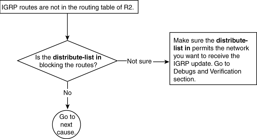
Figure 5-4 Problem-Resolution Flowchart
Debugs and Verification
Example 5-13 shows the current configuration of Router R2. In the access list configuration, the network 131.108.0.0 is not explicitly permitted (and, therefore, is denied), so the router is not installing any subnets of the 131.108.0.0 network.
Example 5-13 R2 Access List Configuration Does Not Permit Routes from the 131.108.0.0 Network
interface Loopback0
ip address 131.108.3.2 255.255.255.0
!
interface Ethernet0
ip address 131.108.1.2 255.255.255.0
!
router igrp 1
network 131.108.0.0
distribute-list 1 in
!
access-list 1 permit 131.107.0.0 0.0.255.255
Solution
When using a distribute list, you should always double-check your access list to make sure that the networks that are supposed to be permitted actually are permitted in the access list definition. In Example 5-13, the access list is permitting only routes from 131.107.0.0. All other routes are denied by the implicit deny at the end of each access list. To fix this problem, explicitly permit 131.108.0.0 in access-list 1.
Example 5-14 shows the new configuration of Router R2 with the correct access list.
Example 5-14 Reconfiguring access-list 1 to Permit Routes from Network 131.108.0.0
interface Loopback0
ip address 131.108.3.2 255.255.255.0
!
interface Ethernet0
ip address 131.108.1.2 255.255.255.0
!
router igrp 1
network 131.108.0.0
distribute-list 1 in
!
no access-list 1 permit 131.107.0.0 0.0.255.255
access-list 1 permit 131.108.0.0 0.0.255.255
Example 5-15 shows that Router R2 is learning IGRP routes after the configuration change.
Example 5-15 show ip route Command Output Reveals That the Change to access-list 1 Was Successful
R2#show ip route 131.108.2.0
Routing entry for 131.108.2.0/24
Known via "igrp 1", distance 100, metric 8976
Redistributing via igrp 1
Advertised by igrp 1 (self originated)
Last update from 131.108.1.1 on Ethernet0, 00:00:12 ago
Routing Descriptor Blocks:
131.108.1.1, from 131.108.1.1, 00:00:12 ago, via Ethernet0
Route metric is 8976, traffic share count is 1
Total delay is 25000 microseconds, minimum bandwidth is 1544 Kbit
Reliability 255/255, minimum MTU 1500 bytes
Loading 1/255, Hops 0
IGRP Routes Not in the Routing Table—Cause: Access List Blocking IGRP Source Address
Access lists are used to filter the traffic based on the source address. Extended access lists are used to filter the traffic based on source or destination address. These access lists can be applied on the interface with the interface-level command ip access-group {access-list number} {in | out} to filter the incoming and outgoing traffic.
When the access list is applied in an IGRP environment, always make sure that it does not block the source address of the IGRP update. In this example, R2 is not installing IGRP routes in the routing table because access-list 1 is not permitting the source address of IGRP updates from R1.
Figure 5-5 shows the flowchart to follow to solve this problem.

Figure 5-5 Problem-Resolution Flowchart
Debugs and Verification
Example 5-16 shows the current configuration of Router R2. The source address of 131.108.1.1 is not being permitted in the access list. Because the only permit statement in the access list is 131.107.0.0, the source address of RIP, 131.108.0.0, will be implicitly denied.
Example 5-16 Current Configuration of Router R2
R2#
interface Loopback0
ip address 131.108.3.2 255.255.255.0
!
interface Ethernet0
ip address 131.108.1.2 255.255.255.0
ip access-group 1 in
!
router igrp 1
network 131.108.0.0
!
access-list 1 permit 131.107.0.0 0.0.255.255
Example 5-17 shows the output of debug ip igrp events and debug ip igrp transaction. In this debug, IGRP is only sending the updates and is not receiving anything because the source address, 131.108.1.1, is not permitted in the input access list of R2. This is also shown in the debug ip packet 100 detail output, where access-list 100 specifically looks at the source address of 131.108.1.1
Example 5-17 debug Command Output Showing That IGRP Updates Are Sent and Not Received
R2#debug ip packet 100 detail
IP: s=131.108.1.1 (Ethernet0), d=255.255.255.255, len 46, access denied, proto=9
R2#
R2#show debug
Generic IP:
IP packet debugging is on (detailed) for access list
100
IP routing:
IGRP protocol debugging is on
IGRP event debugging is on
IGRP: sending update to 255.255.255.255 via Ethernet0
(131.108.1.2)
subnet 131.108.3.0, metric=501
IGRP: Update contains 1 interior, 0 system, and 0
exterior routes.
IGRP: Total routes in update: 1
R2#show access-list 100
Extended IP access list 100
permit ip host 131.108.1.1 host 255.255.255.255
R2#
Solution
The standard access list specifies the source address. In this case, the source address is 131.108.1.1. This source address is not permitted in the standard access list, so IGRP routes will not get installed in the routing table of R2. To solve this problem, permit the source address in access-list 1.
Example 5-18 shows the necessary configuration changes to fix this problem.
Example 5-18 Fixing the Access List to Permit the IGRP Update Source Address
R2#
interface Loopback0
ip address 131.108.3.2 255.255.255.0
!
interface Ethernet0
ip address 131.108.1.2 255.255.255.0
ip access-group 1 in
!
router igrp 1
network 131.108.0.0
!
no access-list 1 permit 131.107.0.0 0.0.255.255
access-list 1 permit 131.108.1.1
Example 5-19 shows the configurations in case of an extended access list.
This problem also can happen when using extended access lists and when the IGRP source address is not permitted in the access list. This solution also can be used in case of extended access list. The idea here is to permit the source address of the IGRP update.
Example 5-19 Fixing the Extended Access List to Permit the IGRP Update Source Address
access-list 100 permit ip 131.107.0.0 0.0.255.255 any
access-list 100 permit ip host 131.108.1.1 any
After changing the access list, standard or extended, and permitting the source address of the neighbor that is sending the IGRP routing updates, R2 will start accepting and installing the IGRP updates.
Example 5-20 shows the routing table entry of Router R2, which shows that it is learning IGRP routes after the configuration change of the access list.
Example 5-20 R2’s Routing Table Verifies That R2 Receives IGRP Routes After Fixing the Access Lists
R2#show ip route 131.108.2.0
Routing entry for 131.108.2.0/24
Known via "igrp 1", distance 100, metric 8976
Redistributing via igrp 1
Advertised by igrp 1 (self originated)
Last update from 131.108.1.1 on Ethernet0, 00:00:12 ago
Routing Descriptor Blocks:
* 131.108.1.1, from 131.108.1.1, 00:00:12 ago, via Ethernet0
Route metric is 8976, traffic share count is 1
Total delay is 25000 microseconds, minimum bandwidth is 1544 Kbit
Reliability 255/255, minimum MTU 1500 bytes
Loading 1/255, Hops 0
IGRP Routes Not in the Routing Table—Cause: Access List Blocking IGRP Broadcast
Access lists are used for the filtering purpose. When used on the inbound interface, always make sure that it is not blocking IGRP broadcast, which is used for IGRP routing updates. If this broadcast address is not permitted in the access list that is applied on the interface inbound, IGRP will not install any routes in the routing table learned on that interface.
Figure 5-6 shows the flowchart to follow to solve this problem.

Figure 5-6 Problem-Resolution Flowchart
Debugs and Verification
Example 5-21 shows the current configuration of R2. In this configuration, the IGRP destination address of 255.255.255.255 is not being permitted; as a result, no IGRP routes are being installed in R2. The access-group 100 in command is configured under the Ethernet 0 interface of R2. This filter actually is calling access-list 100. If you look at access-list 100, it is actually denying the incoming broadcast access on Ethernet 0 interface because there is an implicit deny at the end of each access list. This blocks the IGRP updates, and R2 will not install any IGRP routes.
Example 5-21 R2’s Configuration Does Not Permit the IGRP Broadcast Address of 255.255.255.255
R2#
interface Loopback0
ip address 131.108.3.2 255.255.255.0
!
interface Ethernet0
ip address 131.108.1.2 255.255.255.0
ip access-group 100 in
!
router igrp 1
network 131.108.0.0
!
access-list 100 permit ip 131.107.0.0 0.0.255.255 any
access-list 100 permit ip host 131.108.1.1 host 131.108.1.2
Solution
IGRP broadcasts its routing updates on 255.255.255.255. This address must be permitted in the input access list of the receiving router.
Example 5-22 shows the new configuration for Router R2.
Example 5-22 Reconfiguring Router R2 to Permit the IGRP Broadcast Address
interface Loopback0
ip address 131.108.3.2 255.255.255.0
!
interface Ethernet0
ip address 131.108.1.2 255.255.255.0
ip access-group 1 in
!
router igrp 1
network 131.108.0.0
!
access-list 100 permit ip 131.107.0.0 0.0.255.255 any
access-list 100 permit ip host 131.108.1.1 host 131.108.1.2
access-list 100 permit ip host 131.108.1.1 host 255.255.255.255
Example 5-23 shows the routing table entry of R2 after correcting the problem.
Example 5-23 R2’s Routing Table Shows That the IGRP Broadcast Address Is Now Permitted
R2#show ip route 131.108.2.0
Routing entry for 131.108.2.0/24
Known via "igrp 1", distance 100, metric 8976
Redistributing via igrp 1
Advertised by igrp 1 (self originated)
Last update from 131.108.1.1 on Ethernet0, 00:00:12 ago
Routing Descriptor Blocks:
* 131.108.1.1, from 131.108.1.1, 00:00:12 ago, via Ethernet0
Route metric is 8976, traffic share count is 1
Total delay is 25000 microseconds, minimum bandwidth is 1544 Kbit
Reliability 255/255, minimum MTU 1500 bytes
Loading 1/255, Hops 0
IGRP Routes Not in the Routing Table—Cause: Discontiguous Network
The definition of a discontiguous network is one in which two subnets belonging to the same major network are separated by a network or a subnetwork belonging to another major network. Chapter 4, “Understanding Interior Gateway Routing Protocol (IGRP),” provides a detailed description of why discontiguous networks are not supported in IGRP.
Figure 5-7 shows an example of a discontiguous network in which 137.99.0.0 is a major network. The subnets of this major network are separated by another major network, 131.108.0.0. This situation produces a discontiguous network problem.

Figure 5-7 Sample Discontiguous Network
Figure 5-8 shows the flowchart to follow to solve this problem.
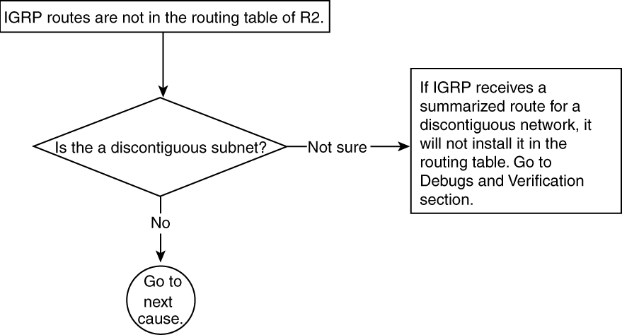
Figure 5-8 Problem-Resolution Flowchart
Debugs and Verification
Example 5-24 shows the configuration of Routers R1 and R2. IGRP is enabled on the Ethernet interfaces of R1 and R2 with the correct network statements.
Example 5-24 R1 and R2 Configurations Indicate That IGRP Is Enabled on the Ethernet Interfaces
R2#
interface Loopback0
ip address 137.99.3.2 255.255.255.0
!
interface Ethernet0
ip address 131.108.1.2 255.255.255.0
!
router igrp 1
network 131.108.0.0
network 137.99.0.0
!
R1#
interface Loopback0
ip address 137.99.2.1 255.255.255.0
!
interface Ethernet0
ip address 131.108.1.1 255.255.255.0
!
router igrp 1
network 131.108.0.0
network 137.99.0.0
!
Example 5-25 shows the debug ip igrp transaction output for Routers R1 and R2. Both debugs show that the network 137.99.0.0 is being sent across.
Example 5-25 debug ip igrp transaction Command Output for R1 and R2 Indicates That Updates for Network 137.99.0.0 Are Being Sent
R2#debug ip igrp transaction
IGRP protocol debugging is on
R2#
IGRP: sending update to 255.255.255.255 via Loopback0 (137.99.3.2)
network 131.108.0.0, metric=8476
IGRP: sending update to 255.255.255.255 via Ethernet0 (131.108.1.2)
network 137.99.0.0, metric=501
IGRP: received update from 131.108.1.1 on Ethernet0
network 137.99.0.0, metric 8976 (neighbor 501)
R2#
R1#debug ip igrp transaction
IGRP protocol debugging is on
R1#
IGRP: sending update to 255.255.255.255 via Loopback0 (137.99.2.1)
network 131.108.0.0, metric=8476
IGRP: sending update to 255.255.255.255 via Ethernet0 (131.108.1.1)
network 137.99.0.0, metric=501
R1#
IGRP: received update from 131.108.1.2 on Ethernet0
network 137.99.0.0, metric 8976 (neighbor 501)
R1#
Solution
IGRP is not installing the route 137.99.0.0 in the routing table because IGRP does not support discontiguous networks. As discussed in Chapter 4, there are several solutions to this problem. The quick solution is to configure a static route to the more specific subnets of 137.99.0.0 on each router. This provides each router the routes about the specific subnets of a discontiguous majornet. Other solutions are as follows:
• Change the address on the link between R1 and R2 to be a part of 137.99.0.0. In other words, assign another subnet on this link, which is a part of 137.99.0.0.
• If the address cannot be changed, run a GRE tunnel between R1 and R2, and put a separate subnet address with the same mask on the tunnel interface, as demonstrated:
R1#
interface tunnel 0
ip address 137.99.1.1 255.255.255.0
tunnel source Ethernet 0
tunnel destination 131.108.1.2
R2#
interface tunnel 0
ip address 137.99.1.2 255.255.255.0
tunnel source Ethernet 0
tunnel destination 131.108.1.1
• Replace IGRP with any other IP routing protocol that supports discontiguous networks—for example OSPF, ISIS, EIGRP, RIP-2, and so on.
Discontiguous subnets are discouraged and should be avoided even if a protocol supports it. They destroy the summarization capabilities.
Example 5-26 shows the configuration change that is required for both Routers R1 and R2 to fix the problem. In the configurations, a static route has been added for the discontiguous subnets.
Example 5-26 Adding a Static Route as a Solution for Discontiguous Subnets
R1#
interface Loopback0
ip address 137.99.3.2 255.255.255.0
!
interface Ethernet0
ip address 131.108.1.1 255.255.255.0
!
router igrp 1
network 131.108.0.0
network 137.99.0.0
!
ip route 137.99.3.0 255.255.255.0 131.108.1.2
R2#
interface Loopback0
ip address 137.99.2.1 255.255.255.0
!
interface Ethernet0
ip address 131.108.1.2 255.255.255.0
!
router igrp 1
network 131.108.0.0
network 137.99.0.0
!
ip route 137.99.2.0 255.255.255.0 131.108.1.1
Example 5-27 shows the routing table entry of R2 after fixing this problem.
Example 5-27 Verifying That the IGRP Routing Update Problem Caused by Discontiguous Networks Has Been Resolved
R2#show ip route 137.99.2.0
Routing entry for 137.99.2.0/24
Known via "igrp 1", distance 100, metric 8976
Redistributing via igrp 1
Advertised by igrp 1 (self originated)
Last update from 131.108.1.1 on Ethernet0, 00:00:12 ago
Routing Descriptor Blocks:
* 131.108.1.1, from 131.108.1.1, 00:00:12 ago, via Ethernet0
Route metric is 8976, traffic share count is 1
Total delay is 25000 microseconds, minimum bandwidth is 1544 Kbit
Reliability 255/255, minimum MTU 1500 bytes
Loading 1/255, Hops 0
IGRP Routes Not in the Routing Table—Cause: Invalid Source
When RIP tells the routing table to install the route, it performs a source validity check. This check makes sure that the source where the update is coming from is also on the same subnet of the local receiving interface. If the source is not on the same subnet as the local interface, RIP ignores the update and will not install routes in the routing table coming from this source address.
Figure 5-9 shows the network diagram for the invalid source problem.

Figure 5-9 Network with an Invalid Source
As Figure 5-9 illustrates, Router 1’s Serial0 interface is unnumbered to Loopback0. Router 2’s serial interface is numbered. When Router 2 receives an IGRP update from Router 1, it complains about the source validity.
Figure 5-10 shows the flowchart to follow to solve this problem.

Figure 5-10 Problem-Resolution Flowchart
Debugs and Verification
Example 5-28 shows the configuration of both Routers R2 and R1, where R1’s Serial0 interface is unnumbered to Loopback0 and R2’s Serial0 interface is numbered.
Example 5-28 R1/R2 Configuration with Mismatched Numbered/Unnumbered Serial Interfaces
R2#
interface Loopback0
ip address 131.108.3.2 255.255.255.0
!
interface Serial0
ip address 131.108.1.2 255.255.255.0
!
router igrp 1
network 131.108.0.0
!
R1#
interface Loopback0
ip address 131.108.2.1 255.255.255.0
!
interface Serial0
ip unnumbered Loopback0
!
router igrp 1
network 131.108.0.0
!
Example 5-29 shows the debug ip igrp transaction output, which reveals that R2 is ignoring IGRP updates from R1 because of the source validity check failure.
Example 5-29 debug ip igrp transaction Command Output Reveals That R2 Is Ignoring IGRP Update from R1
R2#debug ip igrp transaction
IGRP protocol debugging is on
IGRP: received update from invalid source 131.108.2.1 on Serial0
R2#
Solution
When IGRP tells the routing table to install the route, it performs a source validity check. If the source is not on the same subnet on which it received the update, it ignores the update. In cases when one side is numbered and the other side is unnumbered, this check must be turned off. This is usually the case in dial backup situations in which remote routers dial into an access router. The access router’s dialup interface is unnumbered, and all remote routers get an IP address assigned on their dialup interfaces.
Example 5-30 shows the new configuration change on Router R2 to fix this problem.
Example 5-30 Disabling the Source Validity Check on R2
R2#interface Loopback0
ip address 131.108.3.2 255.255.255.0
!
interface Serial0
ip address 131.108.1.2 255.255.255.0
!
router igrp 1
no validate-update-source
network 131.108.0.0
!
Example 5-31 shows that after changing the configurations of R2, the route gets installed in the routing table.
Example 5-31 show ip route Command Output Verifies That R2 Is Now Receiving the IGRP Update from R1’s Unnumbered Interface
R2#show ip route 131.108.2.0
Routing entry for 131.108.2.0/24
Known via "igrp 1", distance 100, metric 8976
Redistributing via igrp 1
Advertised by igrp 1 (self originated)
Last update from 131.108.1.1 on Serial0, 00:00:12 ago
Routing Descriptor Blocks:
* 131.108.1.1, from 131.108.1.1, 00:00:12 ago, via Serial0
Route metric is 8976, traffic share count is 1
Total delay is 25000 microseconds, minimum bandwidth is 1544 Kbit
Reliability 255/255, minimum MTU 1500 bytes
Loading 1/255, Hops 0
IGRP Routes Not in the Routing Table—Cause: Layer 2 Problem (Switch, Frame Relay, Other Layer 2 Media)
Sometimes, broadcast capability is broken at Layer 2, which further affects Layer 3 broadcast, and IGRP fails to work properly. The Layer 3 broadcast is further converted into a Layer 2 broadcast. If Layer 2 has problems in handling Layer 2 broadcasts, the IGRP updates will not be propagated across. The debug shows that the broadcast is being originated at one end but is not getting across.
Figure 5-11 shows the network diagram for a Frame Relay problem while running IGRP.

Figure 5-11 Two Routers Running IGRP in a Frame Relay Network
In Figure 5-11, Router 1 and Router 2 are connected by Frame Relay. (Although, this could be any Layer 2 medium—X.25, Ethernet, FDDI, and so forth.)
Figure 5-12 shows the flowchart to follow to solve this problem.
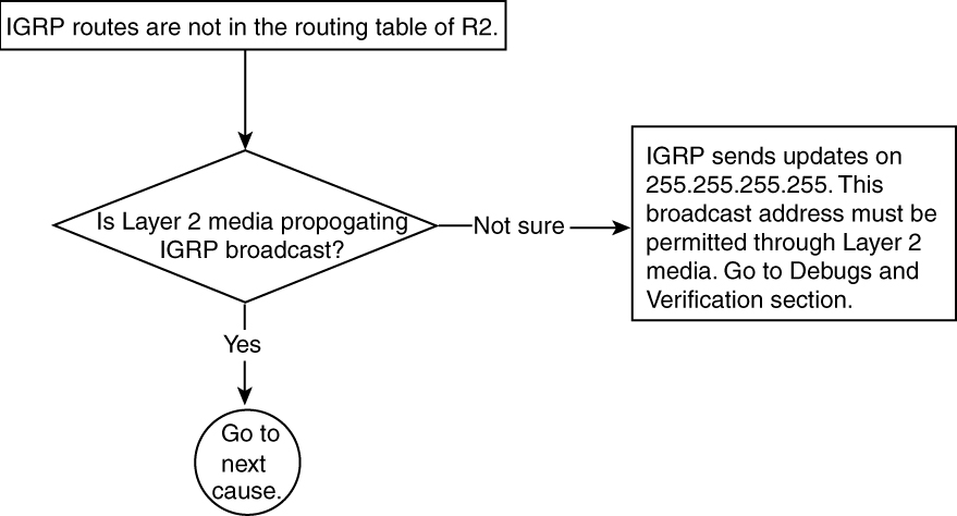
Figure 5-12 Problem-Resolution Flowchart
Debugs and Verification
Example 5-32 shows the output of debug ip packet detail 100, which verifies that R1 is sending and receiving IGRP updates without any problem. On R2, updates are being sent but are not received. This means that the IGRP update is being lost at Layer 2.
Example 5-32 debug ip packet detail 100 Command Output Shows That R1 Is Successfully Sending IGRP Updates
R1#show access-list 100
access-list 100 permit ip any host 255.255.255.255
R1#debug ip packet 100 detail
IP packet debugging is on (detailed) for access list 100
R1#
IP: s=131.108.1.1 (local), d=255.255.255.255 (Ethernet0), len 46, rcvd 2, proto=9
IP: s=131.108.1.2 (Ethernet), d=255.255.255.255, len 46, rcvd 2, proto=9
R2#debug ip packet 100 detail
IP packet debugging is on (detailed) for access list 100
R2#
IP: s=131.108.1.2 (local), d=255.255.255.255 (Ethernet0), len 46, rcvd 2, proto=9
IP: s=131.108.1.2 (local), d=255.255.255.255 (Ethernet0), len 46, rcvd 2, proto=9
Solution
IGRP sends updates on a broadcast address of 255.255.255.255. If this address gets blocked at Layer 2, IGRP will not function properly. The root of the Layer 2 problem could result from a simple Ethernet switch, Frame Relay cloud, bridging cloud, and so on. Fixing the Layer 2 problem is beyond the scope of this book. We will leave this up to you, but here are some tips:
• In cases of Frame Relay
— Check for the broadcast keyword missing in the frame-relay map statement.
— Call your telco and make sure that it is propagating broadcast traffic across.
• In cases of a bridging cloud
— Make sure that any bridge in the middle is not dropping the broadcast packets.
— If the middle medium is Token Ring to Ethernet, make sure that the translational bridging is working properly.
Example 5-33 shows that after fixing the Layer 2 problem, IGRP routes get installed in the routing table.
Example 5-33 Verifying IGRP Routes Show Up in the Routing Table After Resolving the Layer 2 Problem
R2#show ip route 131.108.2.0
Routing entry for 131.108.2.0/24
Known via "igrp 1", distance 100, metric 8976
Redistributing via igrp 1
Advertised by igrp 1 (self originated)
Last update from 131.108.1.1 on Ethernet0, 00:00:12 ago
Routing Descriptor Blocks:
* 131.108.1.1, from 131.108.1.1, 00:00:12 ago, via Ethernet0
Route metric is 8976, traffic share count is 1
Total delay is 25000 microseconds, minimum bandwidth is 1544 Kbit
Reliability 255/255, minimum MTU 1500 bytes
Loading 1/255, Hops 0
IGRP Routes Not in the Routing Table—Cause: Sender’s AS Mismatch
IGRP updates carry the AS number. When a receiver receives an IGRP update and the AS number of the sender does not match with its own AS number, IGRP ignores that update. As a result, no IGRP routes are installed in the routing table. Multiple IGRP processes can be run under different AS numbers. These processes are independent of each other.
Figure 5-13 shows the flowchart to follow to solve this problem.
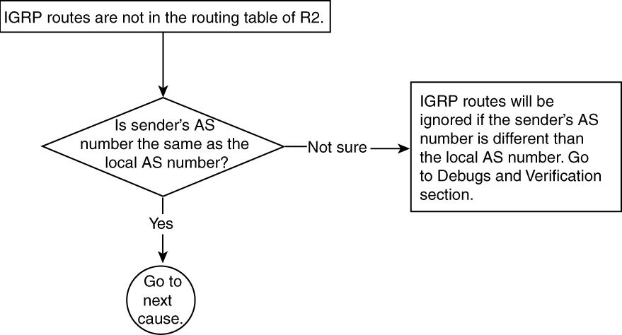
Figure 5-13 Problem-Resolution Flowchart
Debugs and Verification
Example 5-34 shows the configuration of both R1 and R2. R1 is running IGRP AS 1, and R2 is running IGRP AS 2.
Example 5-34 R1 and R2 Configurations Show That They Are in Different Autonomous Systems
R2#
interface Loopback0
ip address 131.108.3.2 255.255.255.0
!
interface Serial0
ip address 131.108.1.2 255.255.255.0
!
router igrp 2
network 131.108.0.0
!
R1#
interface Loopback0
ip address 131.108.2.1 255.255.255.0
!
interface Serial0
ip address 131.108.1.1 255.255.255.0
!
router igrp 1
network 131.108.0.0
!
Example 5-35 shows the output of debug ip igrp transaction and debug ip packet 100 detail on R1 and R2. Both routers are sending the IGRP update, but the update never reaches the other side. Both routers show that the IGRP packets are being received, but IGRP is ignoring these updates because of the AS number mismatch. Unfortunately, the debug does not show the mismatch message; however, it does show that IGRP is not displaying the update received message in the debugs.
Example 5-35 debug ip igrp transaction Command Output on R1 and R2 Reveals the Status of IGRP Updates
R1#show debug
Generic IP:
IP packet debugging is on (detailed)
IP routing:
IGRP protocol debugging is on
IGRP event debugging is on
R1#
R1#show access-list 100
access-list 100 permit ip any host 255.255.255.255
R1#debug ip packet 100 detail
IP packet debugging is on (detailed) for access list 100
R1#
R1#debug ip igrp transaction
IGRP protocol debugging is on
IGRP: sending update to 255.255.255.255 via Serial0 (131.108.1.1)
subnet 131.108.3.0, metric=501
IP: s=131.108.1.2 (Serial0), d=255.255.255.255, len 64, rcvd 2, proto=9
R2#debug ip packet 100 detail
IP packet debugging is on (detailed) for access list 100
R2#
R2#debug ip igrp transaction
IGRP protocol debugging is on
IGRP: sending update to 255.255.255.255 via Serial0 (131.108.1.2)
subnet 131.108.2.0, metric=501
IP: s=131.108.1.1 (Serial0), d=255.255.255.255, len 64, rcvd 2, proto=9
Solution
In this example, the sender is sending AS 1 in the update. When R2 receives it, it ignores this update because R2 is running IGRP under AS 2.
To fix this problem, change the IGRP configurations so that R1 and R2 both agree on one AS number.
Example 5-36 shows the new configuration on R2 that fixes this problem.
Example 5-36 Configuring R2 to Have the Same AS Number as R1
R2#
interface Loopback0
ip address 131.108.3.2 255.255.255.0
!
interface Serial0
ip address 131.108.1.2 255.255.255.0
!
no router igrp 2
!
router igrp 1
network 131.108.0.0
!
Example 5-37 shows that after fixing the AS problem, IGRP routes get installed in the routing table.
Example 5-37 show ip route Command Output Reveals That the AS Problem Preventing IGRP Route Installation Is Resolved
R2#show ip route 131.108.2.0
Routing entry for 131.108.2.0/24
Known via "igrp 1", distance 100, metric 8976
Redistributing via igrp 1
Advertised by igrp 1 (self originated)
Last update from 131.108.1.1 on Serial0, 00:00:12 ago
Routing Descriptor Blocks:
* 131.108.1.1, from 131.108.1.1, 00:00:12 ago, via Serial0
Route metric is 8976, traffic share count is 1
Total delay is 25000 microseconds, minimum bandwidth is 1544 Kbit
Reliability 255/255, minimum MTU 1500 bytes
Loading 1/255, Hops 0
Problem: IGRP Is Not Installing All Possible Equal-Cost Paths—Cause: maximum-paths Restricts IGRP to a Maximum of Four Paths by Default
By default, Cisco routers support only four equal paths, for load-balancing purposes. The command maximum-path can be used for up to six equal-cost paths. If the command is not configured properly, it can cause problems, as discussed in this section. The command maximum-path is incorrectly used, so it allows only one path to the destination even though more than one path exists. The maximum-path 1 command should be used only when load balancing is not desired.
Figure 5-14 shows the network setup that produces the problem of IGRP not installing all possible equal-cost paths.

Figure 5-14 Network Setup Vulnerable to Equal-Cost-Path Routes Not Being Installed by IGRP
Example 5-38 shows the routing table entry of Router R1. Only one route is being installed in the routing table.
Example 5-38 Routing Table for R1 in Figure 5-14
R1#show ip route igrp
131.108.0.0/24 is subnetted, 1 subnets
I 131.108.2.0 [100/8976] via 131.108.5.3, 00:00:09, Ethernet2
Figure 5-15 shows the flowchart to follow to solve this problem.

Figure 5-15 Problem-Resolution Flowchart
Debugs and Verification
Example 5-39 shows the output of the debug ip igrp transaction command on Router R1, revealing that Router R1 is receiving two equal-cost route paths.
Example 5-39 debug ip igrp transaction Command Output Reveals the Number of Equal-Cost Paths Received
R1#debug ip igrp transaction
IGRP protocol debugging is on
IGRP: received update from 131.108.5.3 on Ethernet2
network 137.99.0.0, metric 8976 (neighbor 501)
IGRP: received update from 131.108.1.2 on Ethernet1
network 137.99.0.0, metric 8976 (neighbor 501)
Only one route is installed in the routing table. You see only one route in the routing table instead of two because the operator has configured maximum-paths 1 in the configuration.
Example 5-40 shows the current configuration for Router R1. The maximum-path setting is set to 1, which prevents IGRP from installing more than one path in the routing table. By default, maximum-path is set to 4.
Example 5-40 Current R1 Configuration
router igrp 1
network 131.108.0.0
maximum-paths 1
Solution
By default, Cisco IOS Software allows up to four equal-cost routes to be installed into the routing table. This can be increased up to six routes if configured properly. If there is a desire to do a load balancing over six links, use this command.
Example 5-41 shows the configuration that installs six equal-cost route paths in the routing table.
Example 5-41 Configuring R1 to Accept Up to Six Equal-Cost Route Paths in the Routing Table
R1#router igrp 1
maximum-paths 6
This example makes more sense when you have more than four paths and only four are getting installed in the routing table. Because four equal-cost routes is a default, you must configure maximum-paths to accommodate the fifth and (possibly sixth) route.
Troubleshooting IGRP Routes Advertisement
All these problems discussed so far deal with a problem on the receiving end or a problem in the middle (Layer 2).
There is a third possibility for why the route is not being installed in the routing table—the problem is occurring on the sender’s end. The sender might be having a problem sending IGRP updates, so the receiver is not installing the IGRP routes in the routing table. This next section talks about the things that can go wrong on the sender’s side.
This section discusses the most common scenarios that can prevent IGRP routes from being advertised out. Some cases overlap with IGRP route installation problems—for example, missing network statements and downed interfaces. This section assumes that you did troubleshoot all the possible scenarios discussed in the previous section and that the problems still exist. In this case, the last place to look at is the sender.
This chapter covers two problems related to IGRP route advertisement originating from the sender’s side:
• The sender is not advertising IGRP routes.
• The candidate default is not being advertised.
Problem: Sender Is Not Advertising IGRP Routes
Typically, an IP network running IGRP has routers that have a consistent view of the routing table. In other words, all routers have routing tables that contain reachability information for all the IP subnets of the network. This might differ when filtering of certain subnets is done at some routers and not at others. Ideally, all IGRP routers are aware of all routes of the complete network.
When the routing information differs from one router to the other, one of two possibilities could exist:
• Some router(s) is not advertising the IGRP routes.
• Some router(s) is not receiving the IGRP routes.
This section deals with a router not advertising IGRP routes.
Figure 5-16 provides a network scenario that will be used as the basis for troubleshooting a majority of the following causes of the “sender is not advertising IGRP routes” problem:
• network statement is missing or incorrect.
• The outgoing interface is down.
• distribute-list out is blocking the routes.
• The advertised network interface is down.
• The outgoing interface is defined as passive.
• Broadcast capability has been broken (encapsulation failure in Frame Relay).
• neighbor statement is misconfigured.
• The advertised subnet is VLSM.
• Split horizon is enabled.

Figure 5-16 Network Setup to Illustrate IGRP Routes Not Being Advertised
In Figure 5-16, Router 1 (the sender) is not advertising routes to Router 2. If a network statement is missing from Router 1’s configurations, it will not advertise any IGRP routes.
Sender Is Not Advertising IGRP Routes—Cause: Missing or Incorrect network Statement
One of the requirements for enabling IGRP on a router’s interface is to mention the network statement under the router igrp command. The network statement decides which interface upon which IGRP should be enabled. If the network statement is misconfigured or is not configured, IGRP will not be enabled on that interface and IGRP routes will not be advertised out on that interface.
Figure 5-17 shows the flowchart to follow to fix this problem.

Figure 5-17 Problem-Resolution Flowchart
Debugs and Verification
Example 5-42 shows the current configuration for R1.
Example 5-42 Current Configuration for R1 in Figure 5-16
R1#interface Loopback0
ip address 131.108.2.1 255.255.255.0
!
interface Ethernet0
ip address 131.108.1.1 255.255.255.0
!
router igrp 1
network 131.107.0.0
Solution
The network statement is incorrectly configured under router igrp 1. Instead of 131.108.0.0, 131.107.0.0 is configured. This will not enable IGRP on the interface, and no updates will be sent.
Sometimes, a classless network statement is configured under router IGRP, assuming that it will cover all the networks—for example:
router igrp 1
network 131.0.0.0
This network statement will not cover 131.0.0.0–131.255.255.255 because 131.0.0.0 is a classless network and IGRP is a classful routing protocol. Similarly, if you have multiple Class C addresses, you cannot use one Class C address to cover all the Class C addresses that you own, such as 200.1.1.0–200.1.4.0. This does not mean you can do this:
router igrp 1
network 200.1.0.0
This network statement is meaningless for IGRP because IGRP is a classful protocol. The correct way to advertise all four networks in IGRP is this:
router igrp 1
network 200.1.1.0
network 200.1.2.0
network 200.1.3.0
network 200.1.4.0
Example 5-43 shows the correct configuration for R1.
Example 5-43 R1 Configuration with the Correct network Statement
R1#interface Loopback0
ip address 131.108.2.1 255.255.255.0
!
interface Ethernet0
ip address 131.108.1.1 255.255.255.0
!
router igrp 1
no network 131.107.0.0
network 131.108.0.0
Example 5-44 shows the routing table entry of Router R2, with the learned IGRP route.
Example 5-44 R1 Routing Table Shows That Routes Were Properly Advertised by R2 After Correcting the Configuration
R2#show ip route 131.108.2.0
Routing entry for 131.108.2.0/24
Known via "igrp 1", distance 100, metric 8976
Redistributing via igrp 1
Advertised by igrp 1 (self originated)
Last update from 131.108.1.1 on Serial0, 00:00:12 ago
Routing Descriptor Blocks:
* 131.108.1.1, from 131.108.1.1, 00:00:12 ago, via Serial0
Route metric is 8976, traffic share count is 1
Total delay is 25000 microseconds, minimum bandwidth is 1544 Kbit
Reliability 255/255, minimum MTU 1500 bytes
Loading 1/255, Hops 0
Sender Is Not Advertising IGRP Routes—Cause: Outgoing Interface Is Down
IGRP is the routing protocol that runs on Layer 3. IGRP cannot send updates across the interface if the outgoing interface is down. A variety of possible causes exists for the outgoing interface being down:
• Interface is up, line protocol is down.
• Interface is down, line protocol is down.
• Interface is administratively down, line protocol is down.
If the outgoing interface shows any of these symptoms, IGRP will not be capable of sending any updates across. The main thing to note here is that in all of these possibilities, the line protocol will always appear to be down. This is the most important information in determining the Layer 2 connectivity.
Figure 5-18 shows the flowchart to follow to solve this problem.

Figure 5-18 Problem-Resolution Flowchart
Debugs and Verification
Example 5-45 verifies that the interface Ethernet 0 is down.
Example 5-45 show interface Command Output Reveals That the Interface Is Down
R1#show interface ethernet 0
Ethernet0 is up, line protocol is down
Hardware is Lance, address is 0000.0c70.d31e (bia 0000.0c70.d31e)
Internet address is 131.108.1.1/24
Solution
IGRP runs above Layer 2. IGRP cannot send or receive any routes if Layer 2 is down.
To correct this problem, you must fix the Layer 2 problem. The problem might be as simple as loose cables or a bad cable; in which case, the cable must be replaced. Alter-natively, the problem could be as complex as bad hardware; in which case, the hardware must be replaced. Some of the tips on resolving the Layer 2 issue already were addressed in the “Troubleshooting IGRP Route Installation” section, where the cause is Layer 1/2 being down.
Example 5-46 shows the interface Ethernet 0 after fixing the Layer 2 problem.
Example 5-46 Verifying That the Layer 2 Problem Has Been Resolved
R1#show interface ethernet 0
Ethernet0 is up, line protocol is up
Hardware is Lance, address is 0000.0c70.d31e (bia 0000.0c70.d31e)
Internet address is 131.108.1.1/24
Example 5-47 shows the routing table entry of R2 after fixing the problem.
Example 5-47 Verifying That R2 Is Receiving the Routes After Fixing the Layer 2 Problem
R2#show ip route 131.108.2.0
Routing entry for 131.108.2.0/24
Known via "igrp 1", distance 100, metric 8976
Redistributing via igrp 1
Advertised by igrp 1 (self originated)
Last update from 131.108.1.1 on Serial0, 00:00:12 ago
Routing Descriptor Blocks:
* 131.108.1.1, from 131.108.1.1, 00:00:12 ago, via Serial0
Route metric is 8976, traffic share count is 1
Total delay is 25000 microseconds, minimum bandwidth is 1544 Kbit
Reliability 255/255, minimum MTU 1500 bytes
Loading 1/255, Hops 0
Sender Is Not Advertising IGRP Routes—Cause: distribute-list out Is Blocking the Route
distribute-list out is used to filter any routes that are going to be sent out on an interface. If a receiver is complaining about a missing route that should have been received, make sure that it is not being filtered through distribute-list out. If it is, the associated access list must be modified.
Figure 5-19 shows the flowchart to follow to fix this problem.

Figure 5-19 Problem-Resolution Flowchart
Debugs and Verification
Example 5-48 shows the configuration of Router R1. In this configuration, the access list does not permit the 131.108.0.0 network, so R1 will not advertise any 131.108 network, including 131.108.2.0/24.
Example 5-48 Access List Configuration on R1 Does Not Permit the 131.108.0.0 Network
R1#interface Loopback0
ip address 131.108.2.1 255.255.255.0
!
interface Ethernet0
ip address 131.108.1.1 255.255.255.0
!
router igrp 1
network 131.108.0.0
distribute-list 1 out
!
access-list 1 permit 131.107.0.0 0.0.255.255
Solution
When using a distribute list, you should always double-check your access list to make sure that the networks that are supposed to be permitted actually are explicitly permitted in the access list. The access list configuration in Example 5-48 is permitting only 131.107.0.0 and is denying everything else because there is an implicit deny at the end of each access list. To fix this problem, add a permit statement allowing 131.108.0.0 in access-list 1.
Example 5-49 shows the new configuration change on Router R1.
Example 5-49 Access List Configuration on R1 to Permit the 131.108.0.0 Network
R1#interface Loopback0
ip address 131.108.2.1 255.255.255.0
!
interface Ethernet0
ip address 131.108.1.1 255.255.255.0
!
router igrp 1
network 131.108.0.0
distribute-list 1 out
!
no access-list 1 permit 131.107.0.0 0.0.255.255
access-list 1 permit 131.108.0.0 0.0.255.255
Example 5-50 shows the routing table entry of Router R2 after fixing the problem.
Example 5-50 R2 Routing Table Verifies That R2 Receives IGRP Routes After Fixing the Access List in R2
R2#show ip route 131.108.2.0
Routing entry for 131.108.2.0/24
Known via "igrp 1", distance 100, metric 8976
Redistributing via igrp 1
Advertised by igrp 1 (self originated)
Last update from 131.108.1.1 on Ethernet0, 00:00:12 ago
Routing Descriptor Blocks:
* 131.108.1.1, from 131.108.1.1, 00:00:12 ago, via Ethernet0
Route metric is 8976, traffic share count is 1
Total delay is 25000 microseconds, minimum bandwidth is 1544 Kbit
Reliability 255/255, minimum MTU 1500 bytes
Loading 1/255, Hops 0
Sender Is Not Advertising IGRP Routes—Cause: Advertised Network Interface Is Down
A situation could arise in which the network that is being advertised is down and the connected route has been removed from the routing table. In this situation, IGRP will start advertising that network with an infinite metric and after the hold-down timer expires, it will no longer advertise this network. As soon as the advertised network comes up, IGRP will start advertising it again in its updates.
Figure 5-20 shows the flowchart to follow to fix this problem.

Figure 5-20 Problem-Resolution Flowchart
Debugs and Verification
Example 5-51 shows that the line protocol of the advertised network interface is down, indicating that something is wrong at Layer 2. For tips on fixing Layer 1/2, refer to the “Troubleshooting IGRP Route Installation” section.
Example 5-51 show interface Command Output Reveals That the Advertised Network Interface Is Down
R1#show interface Ethernet 1
Ethernet1 is up, line protocol is down
Hardware is Lance, address is 0000.0c70.d51e (bia 0000.0c70.d51e)
Internet address is 131.108.2.1/24
Solution
When the advertised network’s interface goes down, IGRP will detect that because Layer 2 notifies the upper layer that the interface or the subnet is down. IGRP will no longer advertise that network in the IGRP updates. As Example 5-52 shows, Ethernet 1 is down, so IGRP no longer advertise 131.108.2.0/24 in its update.
To correct this problem, you must fix the Layer 1/2 problem. The problem could be as simple as loose cables, or it could be as complex as bad hardware, in which case the hardware must be replaced. Refer back to the “Troubleshooting IGRP Route Installation” section for tips on fixing Layer 1/2 issues.
Example 5-52 shows that the advertised network interface is up after fixing the Layer 2 problem.
Example 5-52 Verifying That the Advertised Network Interface Is Up
Ethernet1 is up, line protocol is up
Hardware is Lance, address is 0000.0c70.d51e (bia 0000.0c70.d51e)
Internet address is 131.108.2.1/24
Example 5-53 shows that the route that was down is back in the routing table of R2.
Example 5-53 R2 Routing Table Verifies That R2 Starts Receiving IGRP Routes After Fixing the Layer 1/2 Issue
R2#show ip route 131.108.2.0
Routing entry for 131.108.2.0/24
Known via "igrp 1", distance 100, metric 8976
Redistributing via igrp 1
Advertised by igrp 1 (self originated)
Last update from 131.108.1.1 on Ethernet0, 00:00:12 ago
Routing Descriptor Blocks:
* 131.108.1.1, from 131.108.1.1, 00:00:12 ago, via Ethernet0
Route metric is 8976, traffic share count is 1
Total delay is 25000 microseconds, minimum bandwidth is 1544 Kbit
Reliability 255/255, minimum MTU 1500 bytes
Loading 1/255, Hops 0
Sender Is Not Advertising IGRP Routes—Cause: Outgoing Interface Is Defined as Passive
When an interface is defined as passive under IGRP, IGRP will receive updates on that interface but will not send any updates. The passive-interface command is used to avoid sending unnecessary updates to a neighbor that does not need to receive any IGRP updates, such as a small route that is at the edge. A simple default gateway is enough information for that router to talk to the outside world. Be sure to use the passive-interface command where needed; otherwise, undesired results might occur.
Figure 5-21 shows the flowchart to follow to fix this problem.

Figure 5-21 Problem-Resolution Flowchart
Debugs and Verification
Example 5-54 shows the output of show ip protocols, which shows that the outgoing interface is defined as passive.
Example 5-54 Verifying That the Outgoing Interface Is Passive
R1#show ip protocols
Routing Protocol is "IGRP 1"
Sending updates every 30 seconds, next due in 82 seconds
Invalid after 270 seconds, hold down 280, flushed after 630
Outgoing update filter list for all interfaces is
Incoming update filter list for all interfaces is
Default networks flagged in outgoing updates
Default networks accepted from incoming updates
IGRP metric weight K1=1, K2=0, K3=1, K4=0, K5=0
IGRP maximum hopcount 100
IGRP maximum metric variance 1
Redistributing: igrp 1
Routing for Networks:
131.108.0.0
Passive Interface(s):
Ethernet0
Routing Information Sources:
Gateway Distance Last Update
131.108.1.2 100 00:00:09
Distance: (default is 100)
Example 5-55 shows the configuration of Router R1, which shows that the outgoing interface is defined as passive.
Example 5-55 R1 Configuration Shows a Passive Interface
R1#router igrp 1
passive-interface Ethernet 0
network 131.108.0.0
Solution
Example 5-54 and 5-55 confirm that the interface Ethernet 0 is defined as passive, so R1 is not sending any updates on Ethernet 0. Sometimes, it is desirable for some networks to be advertised out and others to be filtered. In this situation, you should not use passive interfaces—distribute-list out is a better solution.
Assuming that passive-interface was configured by mistake, take this command out of the configuration to solve this problem.
Example 5-56 shows the new configuration to solve this problem.
Example 5-56 Removing the Passive Interface
R1#router igrp 1
network 131.108.0.0
no passive-interface Ethernet 0
Example 5-57 shows the routing table entry of R2 after fixing the problem.
Example 5-57 R2’s Routing Table Verifies That Removal of the Passive Interface Fixed Routes Advertisement Problem on R1
R2#show ip route 131.108.2.0
Routing entry for 131.108.2.0/24
Known via "igrp 1", distance 100, metric 8976
Redistributing via igrp 1
Advertised by igrp 1 (self originated)
Last update from 131.108.1.1 on Ethernet0, 00:00:12 ago
Routing Descriptor Blocks:
* 131.108.1.1, from 131.108.1.1, 00:00:12 ago, via Ethernet0
Route metric is 8976, traffic share count is 1
Total delay is 25000 microseconds, minimum bandwidth is 1544 Kbit
Reliability 255/255, minimum MTU 1500 bytes
Loading 1/255, Hops 0
Sender Is Not Advertising IGRP Routes—Cause: Broken Broadcast Capability (Encapsulation Failure in Layer 2)
When IGRP is running in a Frame Relay environment, Layer 2 must support broadcast; otherwise, IGRP updates will not get across. When using static mapping, be sure to add the broadcast keyword at the end of a map statement. This problem also can be seen with X.25, ISDN, and other Layer 2 media. Whenever there is a static mapping, the broadcast keyword must be included in the configuration.
Figure 5-22 shows the network setup that is used to produce a broken broadcast capability in Frame Relay.
Figure 5-22 shows that Router 1 and Router 2 are connected by Frame Relay. Router 1 is not advertising IGRP routes toward Router 2.
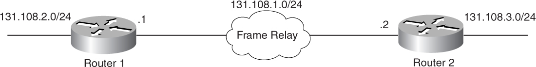
Figure 5-22 Network Setup Incompatible with Frame Relay Broadcasting Without broadcast Keyword in map Statement
Figure 5-23 shows the flowchart to follow to solve this problem.

Figure 5-23 Problem-Resolution Flowchart
Debugs and Verification
Example 5-58 shows the configuration of Router R1. In this configuration, the frame-relay map statement does not include the broadcast keyword.
Example 5-58 R1 Configuration Lacks the broadcast Keyword
R1#interface Serial3
ip address 131.108.1.1 255.255.255.0
no ip directed-broadcast
encapsulation frame-relay
no keepalive
frame-relay map ip 131.108.1.2 16
!
Example 5-59 shows output from the debug ip packet command, which includes the broadcast traffic source from R1. The debug shows that there are encapsulation failures.
Example 5-59 debug ip packet Command Output Indicates Encapsulation Failures
R1#show access-list 100
Extended IP access list 100
permit ip host 131.108.1.1 host 255.255.255.255 (8 matches)
R1#debug ip packet 100 detail
IP packet debugging is on (detailed) for access list 100
R1#
IP: s=131.108.1.1 (local), d=255.255.255.255 (Serial3), len 88, sending broad/
multicast, proto=9
IP: s=131.108.1.1 (local), d=255.255.255.255 (Serial3), len 88, encapsulation failed,
proto=9
Solution
To solve this problem, add the broadcast keyword in the frame-relay map statement.
Example 5-60 shows the new configuration of Router R1 with the correct frame-relay map statement.
Example 5-60 Configuring R1 with the frame-relay map Statement, Including the broadcast Keyword
interface Serial3
ip address 131.108.1.1 255.255.255.0
no ip directed-broadcast
encapsulation frame-relay
no keepalive
frame-relay map ip 131.108.1.2 16 broadcast
!
Example 5-61 shows the routing table entry of R2 with IGRP routes.
Example 5-61 R2 Routing Table Verifies That R2 Is Receiving IGRP Routes After Broadcasting Is Enabled on R2’s frame-relay map Statement
R2#show ip route 131.108.2.0
Routing entry for 131.108.2.0/24
Known via "igrp 1", distance 100, metric 8976
Redistributing via igrp 1
Advertised by igrp 1 (self originated)
Last update from 131.108.1.1 on Serial0, 00:00:12 ago
Routing Descriptor Blocks:
* 131.108.1.1, from 131.108.1.1, 00:00:12 ago, via Serial0
Route metric is 8976, traffic share count is 1
Total delay is 25000 microseconds, minimum bandwidth is 1544 Kbit
Reliability 255/255, minimum MTU 1500 bytes
Loading 1/255, Hops 0
Sender Is Not Advertising IGRP Routes—Cause: Misconfigured neighbor Statement
In a nonbroadcast environment, IGRP provides a unicast method of sending IGRP updates. To send unicast IGRP updates, you must configure the neighbor statement carefully. If the neighbor address is misconfigured in the neighbor statement, IGRP will not send the unicast update to the wrong neighbor or a nonexistent neighbor.
Figure 5-24 shows the flowchart to follow to solve this problem.

Figure 5-24 Problem-Resolution Flowchart
Debugs and Verification
Example 5-62 shows the IGRP configuration for Router R1. The configuration shows that the neighbor statement is configured wrong. Instead of 131.108.1.2, as shown in Figure 5-22, the neighbor statement points to 131.108.1.3, which does not exist.
Example 5-62 Misconfigured neighbor Statement Preventing Unicast IGRP Updates
R1#router igrp 1
network 131.108.0.0
neighbor 131.108.1.3
Solution
In Example 5-62, IGRP is sending a unicast update to 131.108.1.3, a bogus neighbor that does not exist.
To resolve this problem, you must properly configure the neighbor statement.
Example 5-63 shows the correct configuration of Router R1.
Example 5-63 Configuring R1 with the Proper neighbor Statement
R1#router igrp 1
network 131.108.0.0
no neighbor 131.108.1.3
neighbor 131.108.1.2
Example 5-64 shows the IGRP routes installed in R2’s routing table.
Example 5-64 R2’s Routing Table Verifies That the neighbor Statement Has Been Properly Configured on R1, so R2 Starts Receiving IGRP Routes
R2#show ip route 131.108.2.0
Routing entry for 131.108.2.0/24
Known via "igrp 1", distance 100, metric 8976
Redistributing via igrp 1
Advertised by igrp 1 (self originated)
Last update from 131.108.1.1 on Serial0, 00:00:12 ago
Routing Descriptor Blocks:
* 131.108.1.1, from 131.108.1.1, 00:00:12 ago, via Serial0
Route metric is 8976, traffic share count is 1
Total delay is 25000 microseconds, minimum bandwidth is 1544 Kbit
Reliability 255/255, minimum MTU 1500 bytes
Loading 1/255, Hops 0
Sender Is Not Advertising IGRP Routes—Cause: Advertised Subnet Is VLSM
IGRP is not designed to carry subnet mask information; therefore, any subnet that is using a different mask other than the interface that will be sourcing the IGRP update will not be advertised by IGRP, which actually performs a check before sending an update. This check makes sure that the subnet that will be advertised by IGRP has the same subnet mask as the interface that will be sourcing the IGRP update. If the mask is different, IGRP actually drops the update and will not advertise it. Therefore, in IGRP, the subnet mask should be consistent; otherwise, it can cause this problem. This is also explained in detail in Chapter 4.
Figure 5-25 shows a network setup that produces problems because of VLSM. The figure shows that Router 1 has a VLSM subnet that is 131.108.2.0/25. This subnet will not go across toward Router 2.

Figure 5-25 Network Setup Conducive to Advertised Subnet Problems Because of VLSM
Figure 5-26 shows the flowchart to follow to fix this problem.

Figure 5-26 Problem-Resolution Flowchart
Debugs and Verification
Example 5-65 shows that the loopback interface of R1 is configured for a /25 subnet mask and also shows that the interface that will be sourcing the IGRP update has a /24 mask.
Example 5-65 R1’s Loopback Interface Configured with a Subnet Mask Incompatible with the Interface Sourcing the IGRP Update
R1#
interface Loopback0
ip address 131.108.2.1 255.255.255.128
!
interface Ethernet0
ip address 131.108.1.1 255.255.255.0
!
router igrp 1
network 131.108.0.0
Solution
To solve the problem, you need to either change the subnet mask so that it matches the interface that will be sourcing the IGRP update or change the protocol to EIGRP that does support VLSM. Changing the protocol to EIGRP means that every router in the network must be changed to EIGRP, so this is a long-term solution.
Example 5-66 shows the configuration changes that correct the problem.
Example 5-66 Correcting the Mismatched Subnet Mask Problem
R1#
interface Loopback0
ip address 131.108.2.1 255.255.255.0
!
interface Ethernet0
ip address 131.108.1.1 255.255.255.0
!
router igrp 1
network 131.108.0.0
Example 5-67 shows the routing table entry of Router R2 after correcting the problem.
Example 5-67 R2’s Routing Table Verifies That the Mismatched Subnet Mask Problem Has Been Resolved
R2#show ip route 131.108.2.0
Routing entry for 131.108.2.0/24
Known via "igrp 1", distance 100, metric 8976
Redistributing via igrp 1
Advertised by igrp 1 (self originated)
Last update from 131.108.1.1 on Serial0, 00:00:12 ago
Routing Descriptor Blocks:
* 131.108.1.1, from 131.108.1.1, 00:00:12 ago, via Serial0
Route metric is 8976, traffic share count is 1
Total delay is 25000 microseconds, minimum bandwidth is 1544 Kbit
Reliability 255/255, minimum MTU 1500 bytes
Loading 1/255, Hops 0
Sender Is Not Advertising IGRP Routes—Cause: Split Horizon Is Enabled
Split horizon is a feature in IGRP that controls the routing loops. In some situations, it is necessary to enable split horizon to avoid loops—for example, in a normal situation, an IGRP update is received on an interface and is not sent out on the same interface. In other situations, it must be disabled, such as in a hub-and-spoke Frame Relay situation when spokes have no circuit between them and they go through the hub router (see Figure 5-27).

Figure 5-27 Hub-and-Spoke Topology in Which Spokes Do Not Have Any Circuits Between Them
Another unique situation in this example is a router with an external route that has a next-hop address also known through the same interface where other IGRP routers are sitting (see Figure 5-28). When those external routes are redistributed into IGRP, the router does not advertise that route out the same interface because split horizon is enabled. Also, if a secondary address is configured under an interface, split horizon must be turned off on that interface; otherwise, that secondary address will not be advertised out that interface to other routers. In Figure 5-28, some secondary addresses are defined under R1’s Ethernet. For this reason, you must configure no ip split-horizon under R1’s Ethernet interface.

Figure 5-28 Network Setup Conducive to Route Advertisement Problems Because of Split Horizon
Figure 5-28 shows the network setup that produces problems when split horizon is enabled. Router 1 is not advertising all IGRP routes to Router 2.
Figure 5-29 shows the flowchart to follow to fix this problem.
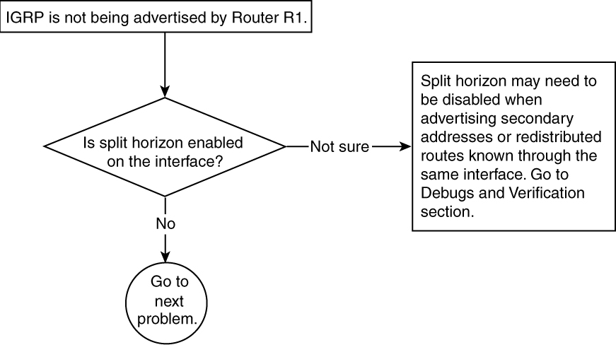
Figure 5-29 Problem-Resolution Flowchart
Debugs and Verification
Example 5-68 shows the current configuration of R1. Note that 166.166.166.0/24 is known through 131.108.1.3. R2 also resides on this subnet, so R1 will not send out any update on this interface because of split horizon.
Example 5-68 R1 Configuration in Which a Static Route’s Next-Hop Address Falls Under Its Connected Subnet Where RIP Is Enabled
R1#
router igrp 1
redistribute static
network 131.108.0.0
!
ip route 155.155.0.0 255.255.0.0 Null0
ip route 166.166.166.0 255.255.255.0 131.108.1.3
Example 5-69 shows that the route 166.166.166.0/24 is not in the routing table of Router R2.
Example 5-69 R2’s Route Table Indicates That the 166.166.166.0/24 Route Is Missing
R2#show ip route igrp
I 155.155.0.0/16 [100/8496] via 131.108.1.1, 00:00:07, Ethernet0
Example 5-70 shows the debug ip igrp transaction output on Router R1, which is advertising 155.155.0.0/16 but not 166.166.166.0/24. In R2’s routing table, no route exists for 166.166.166.0/24.
Example 5-70 debug ip igrp transaction Command Output Shows That 166.166.166.0/24 Is Not Being Advertised
R1#debug ip igrp transaction
IGRP protocol debugging is on
IGRP: sending update to 255.255.255.255 via Ethernet0 (131.108.1.1)
network 155.155.0.0, metric=501
Solution
This problem happens because the next hop of 166.166.166.0/24 is 131.108.1.3. Under split horizon, IGRP will suppress this update on the interface where 166.166.166.0/24 is learned. Because of this, IGRP will not advertise 166.166.166/24 out the same interface where it is learned.
The solution lies in turning off split horizon on R1’s Ethernet 0 interface.
Example 5-71 shows the corrected configuration on Router R1 to solve this problem.
Example 5-71 Disabling Split Horizon on R1 Ethernet 0 Interface
interface Ethernet0
ip address 131.108.1.1 255.255.255.0
no ip split-horizon
Example 5-72 shows that, after making the configuration changes, R2 is receiving 166.166.0.0/16 in the IGRP updates. Note that, because it is crossing the major network boundary, R1 will autosummarize it and send 166.166.0.0. This is why the routing table shows 166.166.0.0 instead of 166.166.166.0.
Example 5-72 R2’s Routing Table Indicates That Disabling Split Horizon on R1 Has Enabled the Advertisement of 166.166.166.0/24
R2#show ip route igrp
I 155.155.0.0/16 [100/8496] via 131.108.1.1, 00:00:08, Ethernet0
I 166.166.0.0/16 [100/8496] via 131.108.1.1, 00:00:08, Ethernet0
This problem also can occur when interfaces are configured with secondary IP addresses.
Example 5-73 shows the interface configuration with a secondary IP address.
Example 5-73 R1’s Ethernet 0 Interface Configured with a Secondary IP Address
R1#
interface Ethernet0
ip address 131.108.2.1 255.255.255.0 secondary
ip address 131.108.1.1 255.255.255.0
If split horizon is enabled, this secondary address will not be advertised on Ethernet 0.
Similarly, imagine a situation in which there are three routers—R1, R2, and R3—on the same Ethernet, as shown in Figure 5-30.

Figure 5-30 Network with Three Routers on the Same Ethernet Network
R1 and R3 are running OSPF. R1 and R2 are running IGRP. Now R3 advertises certain routes through OSPF to R1 that R1 has to redistribute into IGRP. R1 will not advertise those OSPF routes to R2 because of split horizon. Again, the solution is to disable split horizon.
Basically, these are the three main reasons for turning off the split horizon. Any other situation might create a routing loop if split horizon is turned off.
Problem: Candidate Default Is Not Being Advertised—Cause: ip default-network Command Is Missing
In a classless environment, when a router needs to send a packet to a particular destination, it performs the following check in this order:
1 Is the destination address one of my connected interface addresses? If yes, use ARP for the address and then encapsulate the packet in an Ethernet frame and send it to the destination.
2 If no, do I have a route in my routing table for this destination address? If yes, use that route from the routing table and send the packet.
3 If no, check whether the gateway of last resort is set. If it is set, send the packet to the address mentioned in the gateway of last resort. (In Example 5-74, the packets will be sent to 131.108.1.1. If there is no gateway of last resort, the packet is dropped.)
Example 5-74 shows that the gateway of last resort is set to 131.108.1.1. This means that if a router does not have an entry in the routing table, it will send the packet to 131.108.1.1.
Example 5-74 Verifying That a Gateway of Last Resort Is Set
R1# show ip route
Gateway of last resort is 131.108.1.1 to network 0.0.0.0
In any routing protocol except IGRP, the way to set the gateway of last resort is to define a static route 0.0.0.0 with the mask of 0.0.0.0 and a next-hop address, as shown in Example 5-75; however, IGRP cannot understand 0.0.0.0, so there is a separate way to set the gateway of last resort in IGRP.
Example 5-75 Configuring a Default Route to Set the Gateway of Last Resort
R1(config-term)#ip route 0.0.0.0 0 0.0.0.0 131.108.1.1
Figure 5-31 shows the flowchart to follow to fix this problem.
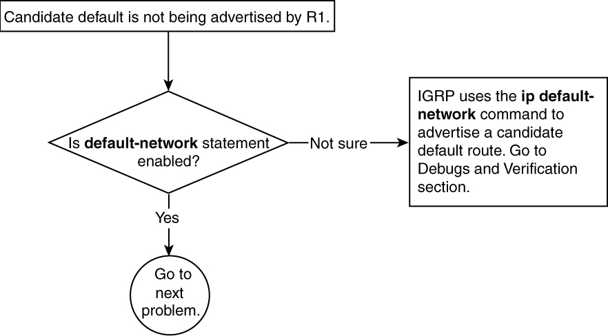
Figure 5-31 Problem-Resolution Flowchart
Debugs and Verification
Example 5-76 shows the configuration of R1. No default-network statement is configured.
Example 5-76 R1’s Configuration Reveals That a Candidate Default Route Has Not Been Configured
R1#interface Loopback1
ip address 131.108.2.1 255.255.255.0
!
interface Loopback3
ip address 155.155.155.1 255.255.255.0
!
interface Ethernet0
ip address 131.108.1.1 255.255.255.0
!
router igrp 1
network 131.108.0.0
network 155.155.0.0
Example 5-77 shows the routing table in Router R2, which R2 is receiving 155.155.155.0/24, but it is not a candidate for default because it is not configured as a candidate for default route.
Example 5-77 R2’s Routing Table
R2#show ip route igrp
I 155.155.0.0/24 [100/8976] via 131.108.1.1, 00:00:22, Serial0
131.108.0.0/24 is subnetted, 3 subnets
I 131.108.2.0 [100/8976] via 131.108.1.1, 00:00:22, Serial0
Solution
IGRP is incapable of carrying the 0.0.0.0/0 (also known as default route), as explained in the problem section. Instead, it follows the default-network command to mark a network as a candidate for default.
In this example, R1 is sending 155.155.155.0/24, and it is desirable to make R1 a candidate for default. To do that, change the configuration on R1 and establish the 155.155.0.0 network as the default network. Upon doing this, IGRP will automatically start treating 155.155.155.0/24 as the candidate for default and will set the gateway of last resort on R2.
Example 5-78 shows the configuration for default-network on R1. This default-network statement must always point toward a major network, not a subnet; otherwise, it will not set the gateway of last resort.
Example 5-78 Configuring 155.155.0.0 as the Default Network
R1(config-term)#ip default-network 155.155.0.0
Example 5-79 illustrates that after the configuration change on R1, the debug ip igrp transaction output shows IGRP treating 155.155.155.0/24 route as an exterior route because it is marked as a candidate for default route.
Example 5-79 IGRP Treats 155.155.0.0 as an Exterior Route
IGRP: received update from 131.108.1.1 on Serial1
subnet 131.108.3.0, metric 8976 (neighbor 501)
subnet 131.108.1.0, metric 10476 (neighbor 8476)
exterior network 155.155.0.0, metric 8976 (neighbor 501)
Example 5-80 now shows that the gateway of last resort is set and that 155.155.155.0/24 is marked as a candidate for default. Also, the * next to the I in the routing table entry means that this entry is a candidate for a default route.
Example 5-80 R2’s Routing Table Indicates the Candidate for Default and Shows That the Gateway of Last Resort Is Set to 155.155.0.0
R2#show ip route
Gateway of last resort is 131.108.1.1 to network 155.155.0.0
137.99.0.0/24 is subnetted, 1 subnets
C 137.99.3.0 is directly connected, Loopback0
I* 155.155.0.0/16 [100/8976] via 131.108.1.1, 00:01:17, Serial1
Troubleshooting IGRP Redistribution Problems
This section covers a common problem that can happen during redistribution in IGRP. Redistribution occurs when another routing protocol, static route, or connected route is being injected into IGRP. Special care is required during this process to avoid any routing loops. Metrics also should be defined during this process, to avoid problems.
The most prevalent problem encountered with IGRP redistribution is that redistributed routes are not getting installed in the routing table of the IGRP routers receiving these routes. When destination routes are not present in the routing table, no data can reach those destinations.
Problem: Redistributed Routes Are Not Getting Installed in the Routing Table—Cause: Metric Is Not Defined During Redistribution into IGRP
IGRP has a composite metric made up of bandwidth, delay, reliability, load, and MTU; however, by default, it utilizes only bandwidth and delay. OSPF’s metric is based on interface cost. Cost is derived from the bandwidth of the link. Cisco uses 100,000,000/bandwidth to get the cost. IGRP does not understand the metrics of other protocols (except EIGRP) so it is necessary to input a default metric when doing redistribution.
Figure 5-32 shows the network setup susceptible to the problem in which redistributed routes do not get installed in the routing table.
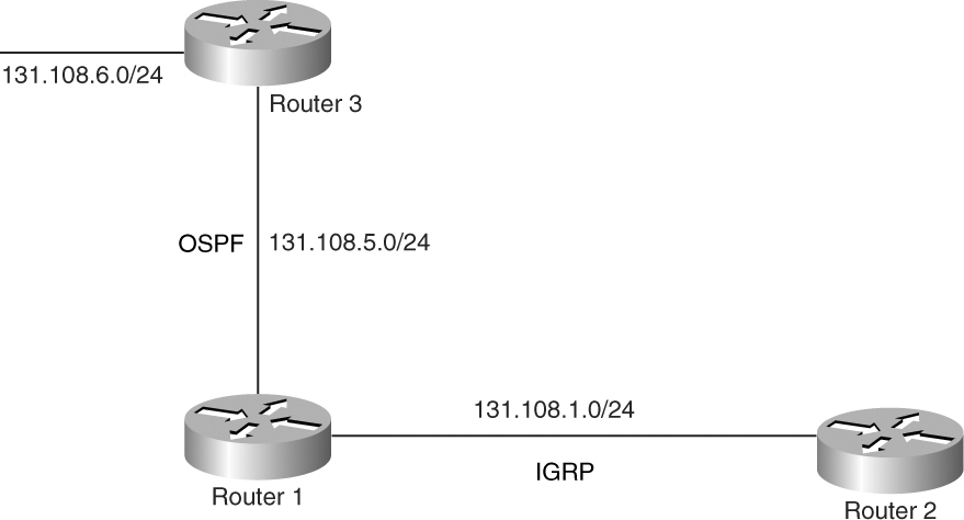
Figure 5-32 Network Setup Conducive to Redistributed Routes Not Being Installed in the Routing Table
OSPF is redistributed into IGRP at R1, but R2 is not receiving IGRP routes that are OSPF routes in R1.
Figure 5-33 shows the flowchart to follow to solve this problem.
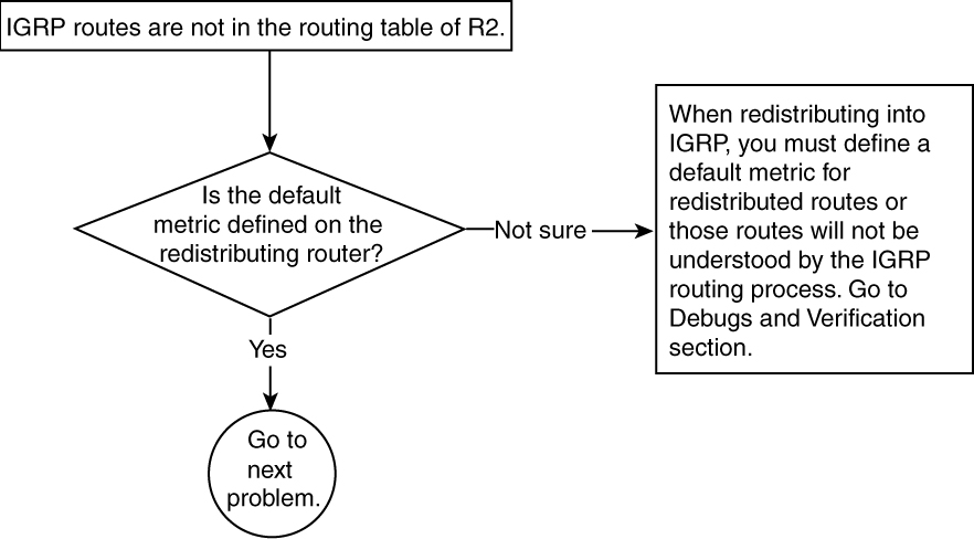
Figure 5-33 Problem-Resolution Flowchart
Debugs and Verification
Example 5-81 shows that R3 is advertising 131.108.6.0/24 through OSPF to R1.
Example 5-81 R1’s Routing Table Shows That R3 Is Advertising 131.108.6.0/24 Through OSPF
R1#show ip route 131.108.6.0
Routing entry for 131.108.6.0/24
Known via "ospf 1", distance 110, metric 20, type intra area
Example 5-82 shows that R1 is redistributing OSPF in IGRP.
Example 5-82 R1 Configuration to Redistribute OSPF into IGRP
R1#
router igrp
redistribute ospf 1
network 131.108.0.0
Example 5-83 shows that in R2, 131.108.6.0/24 is not present in the IGRP routing table.
Example 5-83 R2’s Routing Table Is Missing the Redistributed Route
R2#show ip route 131.108.6.0
% Subnet not in table
Solution
To solve this problem, R1 needs to put a metric command under the router igrp statement so that it can calculate the OSPF metric properly.
Example 5-84 shows the new configuration for R1. OSPF is redistributed into IGRP with metric values of bandwidth, delay, load, reliability, and MTU. Setting low bandwidth and high delay yields to a high metric for redistributed routes.
Example 5-84 Configuring R1 to Calculate OSPF Metrics
R1#router igrp 1
redistribute ospf 1 metric 1 10000 255 1 1500
network 131.108.0.0
Another way to fix this problem is to define a default metric under the router igrp statement. The difference between using a default metric and defining a metric as shown in Example 5-84 is that a default metric will be used for all the redistribution. For example, if the router igrp statement has multiple redistribution commands, all the redistributed routes will have a default metric value defined under the router igrp command.
Example 5-85 shows the syntax for default-metric command under the router igrp statement when redistributing into IGRP. The metric values are based on bandwidth, delay, load, reliability, and MTU. So, in this case, all the static and OSPF routes will be redistributed with the default metric configured here.
Example 5-85 Configuring a Default Metric
R1#router igrp 1
redistribute ospf 1
redistribute static
default-metric 1 10000 255 1 1500
network 131.108.0.0
Example 5-86 shows that the route gets installed in the routing table.
Example 5-86 R2’s Routing Table Verifies That the New Configuration for R1 Has Corrected the Problem
R2#show ip route 131.108.6.0
Routing entry for 131.108.6.0/24
Known via "igrp", distance 100, metric 8976
Troubleshooting Dial-on-Demand Routing (DDR) Issues in IGRP
Dial-on-demand routing is very common when the ISDN or similar dialup links are used as a backup link. When the primary link goes down, this backup link comes up. IGRP starts sending and receiving updates on this link as long as the primary link is down.
Two ways exist for using the dialup links as a backup for the primary link:
• Using the backup interface command
• Using floating static routes with a dialer list that defines interesting traffic
The first method is simple: The command is typed under the dial interface indicating that it is a backup for a primary interface.
The second method requires a floating static route with a higher administrative distance than IGRP—for example, 110 or above. It also requires defining interesting traffic that should bring up the link. The IGRP broadcast address of 255.255.255.255 must be denied in the dialer list, so it should not bring up the link unnecessarily.
When running IGRP under dial backup situations, a lot of issues must be considered. Some problems are related to the ISDN line or async line that keeps coming up. Some problems are related to the configuration. This section talks about the two most common dial backup problems:
• IGRP broadcast is keeping the link up.
• IGRP updates are not going across dialer interface.
Problem: IGRP Broadcast Is Keeping the ISDN Link Up—Cause: IGRP Broadcasts Have Not Been Denied in the Interesting Traffic Definition
ISDN links typically are used as backup links when primary links go down. Cisco IOS Software requires that routers are instructed on the kind of traffic that can bring up the ISDN link and keep it up. Such traffic is called interesting traffic. Network operators typically want data traffic to be considered as interesting traffic, to bring up and keep up the ISDN link. IGRP or other routing protocol updates should not be defined as interesting traffic. If this is not done, the ISDN link comes up and stays up as long as routing updates (IGRP, in this case) are taking place on a regular basis. That is not the desired behavior because ISDN provides low-speed connectivity and because some data actually could go over the slow link even though the primary faster link is available.
Figure 5-34 shows the network setup susceptible to dial backup issues.

Figure 5-34 Network Setup Conducive to Dial Backup Problems
Figure 5-35 shows the flowchart to follow to fix this problem.

Figure 5-35 Problem-Resolution Flowchart
Debugs and Verification
Example 5-87 shows the configuration on Router R1 that produces this problem. In this configuration, only TCP traffic is denied. In other words, TCP traffic will not bring up and keep up the link. IGRP broadcasts are IP packets; because the permit ip any any command allows any IP traffic to go through besides TCP, IGRP broadcast traffic will be considered interesting traffic.
Example 5-87 R1 Configuration in Which IGRP Broadcasts Are Not Denied
R1#
interface BRI3/0
ip address 192.168.254.13 255.255.255.252
encapsulation ppp
dialer map ip 192.168.254.14 name R2 broadcast 57654
dialer-group 1
isdn switch-type basic-net3
ppp authentication chap
access-list 100 deny tcp any any
access-list 100 permit ip any any
dialer-list 1 protocol ip list 100
Example 5-88 shows the output of show dialer, which indicates that the reason for the link coming up is IGRP broadcast.
Example 5-88 show dialer Output Indicates the Last Time the Link Was Up Was Because of IGRP Broadcast
R1#show dialer
BRI1/1:1 - dialer type = ISDN
Idle timer (120 secs), Fast idle timer (20 secs)
Wait for carrier (30 secs), Re-enable (2 secs)
Dialer state is data link layer up
Dial reason: ip (s=192.168.254.13, d=255.255.255.255)
Current call connected 00:00:08
Connected to 57654 (R2)
Solution
When running IGRP and DDR, define the access list to define the interesting traffic. In Example 5-87, the access list is denying only the TCP traffic and is permitting all the IP traffic. IGRP uses an IP broadcast address of 255.255.255.255 to send the routing updates. This address must be denied in the access list so that IGRP does not bring up the link every 90 seconds.
Example 5-89 shows the correct configuration change in Router R1. In this configuration, all traffic destined to the 255.255.255.255 address is denied. This covers IGRP broadcast, so IGRP will not bring up the link after this configuration change.
Example 5-89 Configuring R1’s Access List to Deny IGRP Broadcast Traffic
R1#
access-list 100 deny tcp any any
access-list 100 deny ip any 255.255.255.255
access-list 100 permit ip any any
dialer-list 1 protocol ip list 100
Problem: IGRP Updates Are Not Going Across the Dialer Interface—Cause: Missing Broadcast Keyword in a dialer map Statement
When a dialer interface—say, ISDN—comes up, it could be desirable to run a routing protocol over this link. Static routes might do the job, but in networks with a large number of routes, static routes might not scale well. Therefore, running a dynamic routing protocol is necessary. In some situations, the ISDN link is up but no routing information is going across. Without a routing protocol, no destination addresses can be learned and no traffic can be sent to those destinations. This problem needs to be fixed because ISDN interfaces are of no use when not carrying any traffic.
Figure 5-36 shows the flowchart to follow to solve this problem.

Figure 5-36 Problem-Resolution Flowchart
Debugs and Verification
Example 5-90 shows the configuration on R1 that produces this problem. The dialer map is used to map the neighbor IP address with a string, which is normally an ISDN number. This is called a static mapping for dialer. When using static mapping, the keyword broadcast must be included at the end; otherwise, it will not propagate the broadcast traffic across the link.
Example 5-90 R1 Configuration Preventing IGRP Updates Across Dialer Interface
R1#
interface BRI3/0
ip address 192.168.254.13 255.255.255.252
encapsulation ppp
dialer map ip 192.168.254.14 name R2 57654
dialer-group 1
isdn switch-type basic-net3
ppp authentication chap
Example 5-91 shows that IGRP is sending the broadcast update toward R2, but because of an encapsulation failure, it is not getting on the other side.
Example 5-91 Confirming an Encapsulation Failure
R1#show access-list 100
access-list 100 permit ip any host 255.255.255.255
R1#debug ip packet 100 detail
IP: s=192.168.254.13 (local), d=255.255.255.255 (BRI3/0), len 46, sending broad/
multicast, proto=9
IP: s=192.168.254.13 (local), d=255.255.255.255 (BRI3/0), len 72, encapsulation
failed, proto=9
Solution
This problem occurs because IGRP uses broadcasts to send its routing updates. When using dialer map statements, you must include the broadcast keyword; otherwise, the broadcast will not be allowed to cross the circuit and the encapsulation failures occur. To correct this problem, add the broadcast keyword in the dialer map statement.
Example 5-92 shows the new configuration change on Router R1.
Example 5-92 Configuring R1 to Allow Broadcasts Across the Dialer Interface
interface BRI3/0
ip address 192.168.254.13 255.255.255.252
encapsulation ppp
dialer map ip 192.168.254.14 name R2 broadcast 57654
dialer-group 1
isdn switch-type basic-net3
ppp authentication chap
Troubleshooting Route Flapping Problem in IGRP
Running IGRP in a complex environment sometimes can cause flapping of routes. Route flapping means that the routes keep coming and going from the routing table. To see whether the routes are indeed flapping, check the routing table and look at the age of the routes. If the ages are constantly getting reset to 00:00:00, the routes are flapping. There could be several reasons for this. This section discusses one of the most common reasons—packet loss. Packet loss prevents an IGRP update from reaching the other side.
The example in this section considers Frame Relay because it is the most common medium in which this problem occurs. The packet loss can be verified through the interface statistics by looking at the number of packet drops and seeing if it is constantly incrementing.
Problem: IGRP Routes Are Flapping—Cause: Packet Drops on Sender’s or Receiver’s Interface
When IGRP is used in a large Frame Relay environment where there are several neighbors on one Frame Relay interface, there is a possibility of a packet loss. The packet loss in IGRP means that the whole update is lost. If a sender or receiver drops an IGRP update, it has to wait for another update because the IGRP updates are not retransmitted after it is lost.
The most common reason for packet drops on Frame Relay interfaces is a result of broadcast drops in the broadcast queue of Frame Relay. Broadcast queues in Frame Relay are designed to carry all the broadcast traffic. If there is a lot of broadcast traffic, the broadcast queue needs to be tuned.
Figure 5-37 shows the network setup susceptible to a IGRP route-flapping problem.
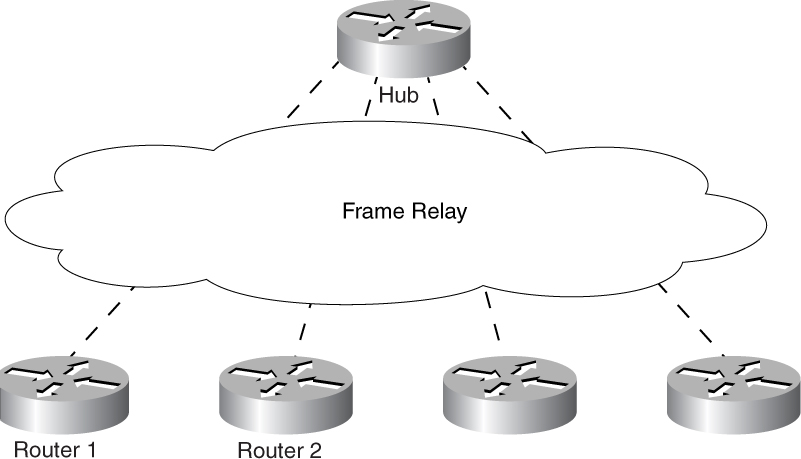
Figure 5-37 Network Setup Conducive to Route Flapping
Figure 5-38 shows the flowchart to follow to solve this problem.
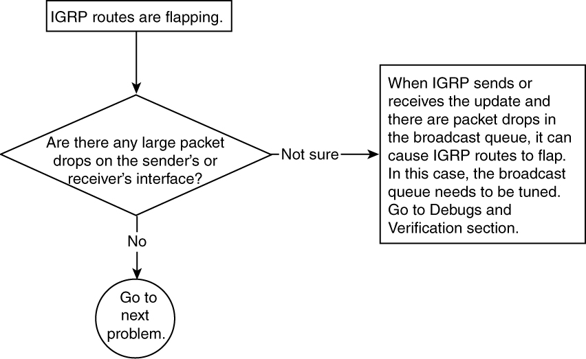
Figure 5-38 Problem-Resolution Flowchart
Debugs and Verification
The show ip route output in Example 5-93 shows that the routes are 3:08 old, so it has missed two updates. If IGRP does not receive a route for 270 seconds, the route will be put into holddown. This situation gets corrected by itself, but, in some cases, changes to the configuration are required. For example, consider the output in Example 5-93.
Example 5-93 show ip route igrp Command Output Indicates That IGRP Did Not Receive Updates for 3 Minutes and 8 Seconds
Hub#show ip route igrp
I 155.155.0.0/16 [100/8242] via 131.108.1.1, 00:03:08, Serial0
I 166.166.0.0/16 [100/8242] via 131.108.1.1, 00:03:08, Serial0
The output in Example 5-93 shows that no IGRP update has been received since 3 minutes and 8 seconds. This means that two IGRP updates have been missed.
Example 5-94 shows that there are a large number of broadcast drops on the interface. The broadcast queue size also is 64, which is the default, and it must be increased.
Example 5-94 Serial Interface Shows That the Broadcast Queue Is Dropping a Large Number of Packets
Hub#show interface serial 0
Serial0 is up, line protocol is up
Hardware is MK5025
Description: Charlotte Frame Relay Port DLCI 100
MTU 1500 bytes, BW 1024 Kbit, DLY 20000 usec, rely 255/255, load 44/255
Encapsulation FRAME-RELAY, loopback not set, keepalive set (10 sec)
LMI enq sent 7940, LMI stat recvd 7937, LMI upd recvd 0, DTE
LMI up
LMI enq recvd 0, LMI stat sent 0, LMI upd sent 0
LMI DLCI 1023 LMI type is CISCO frame relay DTE
Broadcast queue 64/64, broadcasts sent/dropped 1769202/1849660, interface
broadcasts 3579215
Solution
The output in Example 5-94 further proves that there is some problem at the interface level. Too many drops are occurring at the interface level. This is causing the route flapping. To correct this problem, you must tune the Frame Relay broadcast queue accordingly. Tuning the Frame Relay broadcast queue is beyond the scope of this book. Several papers on the Cisco web site discuss how to tune the Frame Relay broadcast queue:
www.cisco.com/warp/partner/synchronicd/cc/techno/media/wan/frame/prodlit/256_pb.htm
www.cisco.com/warp/public/125/20.html
Example 5-95 shows that after fixing the interface drop problem, route flapping disappears. The broadcast queue size is changed from 64 to 256. The correct number can be determined after reading the URL mentioned earlier for tuning the broadcast queue.
Example 5-95 Verifying That the Serial Interface Is Not Dropping Any Broadcast Traffic in the Broadcast Queue
Hub#show interface serial 0
Serial0 is up, line protocol is up
Hardware is MK5025
Description: Charlotte Frame Relay Port DLCI 100
MTU 1500 bytes, BW 1024 Kbit, DLY 20000 usec, rely 255/255, load 44/255
Encapsulation FRAME-RELAY, loopback not set, keepalive set (10 sec)
LMI enq sent 7940, LMI stat recvd 7937, LMI upd recvd 0, DTE LMI up
LMI enq recvd 0, LMI stat sent 0, LMI upd sent 0
LMI DLCI 1023 LMI type is CISCO frame relay DTE
Broadcast queue 0/256, broadcasts sent/dropped 1769202/0, interface broadcasts
3579215
Example 5-96 shows that the show ip routes output verifies that the routes are stable in the routing table.
Example 5-96 Verifying Stable Routes
Hub#show ip route igrp
I 155.155.0.0/16 [100/8242] via 131.108.1.1, 00:00:07, Serial0
I 166.166.0.0/16 [100/8242] via 131.108.1.1, 00:00:07, Serial0
Troubleshooting Variance Problem
Variance is a unique feature of IGRP (and EIGRP) that distinguishes it from RIP. Variance is basically a way to load-balance the traffic on unequal-cost paths.
All routing protocols support equal-cost-path load balancing, but only IGRP and EIGRP support unequal-cost-path load balancing, which is configured using a variance command. Configuration of variance is easy, as long as you know the concept behind it.
The variance command instructs the router to include routes with a metric smaller than n times the minimum metric route for that destination, where n is the number specified by the variance command.
Problem: IGRP Not Using Unequal-Cost Path for Load Balancing—Cause: variance Command Is Missing or Misconfigured
To use the variance feature (unequal-cost-path load balancing), it must be configured under the router igrp command. By default, IGRP does not do unequal-cost-path load balancing. Also, when the variance factor is multiplied by the current best metric, the resulting number is compared with other available path metrics. Any available path metric that is under this resulting number will be used for unequal-path load balancing.
Figure 5-39 shows the network setup susceptible to this problem. The network 155.155.0.0/16 is known through two paths, but only one is in the routing table.

Figure 5-39 Network Setup Conducive to Load-Balancing Problems
Figure 5-40 shows the flowchart to follow to solve this problem.

Figure 5-40 Problem-Resolution Flowchart
Debugs and Verification
Example 5-97 shows the routing table entry on R1 showing that R1 is using only one path to reach 155.155.0.0/16.
Example 5-97 R1 Routing Table Entry Shows That Only a Single Path Is Used to Reach the Destination Network
R1#show ip route 155.155.0.0
Routing entry for 155.155.0.0/16
Known via "igrp 1", distance 100, metric 8976
Redistributing via igrp 1
Advertised by igrp 1 (self originated)
Last update from 131.108.6.2 on Serial2, 00:00:03 ago
Routing Descriptor Blocks:
* 131.108.6.2, from 131.108.6.2, 00:00:03 ago, via Serial2
Route metric is 8976, traffic share count is 1
Total delay is 25000 microseconds, minimum bandwidth is 1544 Kbit
Reliability 255/255, minimum MTU 1500 bytes
Loading 1/255, Hops 0
Example 5-98 shows the interface configuration on both Serial2 and Serial3. Bandwidths are equal in this example, but they could have different values in different scenarios.
Example 5-98 R1’s Serial2 and Serial3 Interface Configurations
R1#show interface serial2
Serial2 is up, line protocol is up
Hardware is HD64570
Internet address is 131.108.6.1/24
MTU 1500 bytes, BW 1544 Kbit, DLY 400000 usec, rely 255/255, load 1/255
R1#show interface serial3
Serial3 is up, line protocol is up
Hardware is HD64570
Internet address is 131.108.7.1/24
MTU 1500 bytes, BW 1544 Kbit, DLY 20000 usec, rely 255/255, load 1/255
Example 5-99 shows the IGRP configuration on R1. The variance command is configured, but the multiplier has the wrong value. The metric from Serial3 is more than five times larger, which is why the variance is not working. If you multiply the metric value of Serial2 (which is 8976) by 5, you get 44,880, which is still not enough because the metric for Serial3 is 46,976.
Example 5-99 Improperly Configured Variance Value
R1#
!
router igrp 1
variance 5
network 131.108.0.0
Solution
To solve this problem, choose a variance factor that yields a metric that is higher then the one being used by another unequal-cost path. For example, when you multiply the current metric of 8796 by 6 instead of 5, you get a value of 52,776. So, any link that has a metric value of less than 52,776 will be used in this unequal-cost-path load balancing. In this example, Serial3 has a metric value of 46,976. Because this number is less than 52,776, it is used for load balancing.
In Example 5-99, the second link metric is more than five times larger than the current metric. Example 5-100 shows that by changing the variance value to 6, IGRP starts including the second path.
Example 5-100 Correcting the Variance So That IGRP Uses Both Paths
R1#!
router igrp 1
variance 6
network 131.108.0.0
Example 5-101 shows that R1 is installing both paths in the routing table, but with the traffic share count ratio equal to 5.
Example 5-101 R1 Routing Table Shows the Traffic Share Count Ratio
R1#show ip route 155.155.0.0
Routing entry for 155.155.0.0/16
Known via "igrp 1", distance 100, metric 8976
Redistributing via igrp 1
Advertised by igrp 1 (self originated)
Last update from 131.108.7.2 on Serial3, 00:00:07 ago
Routing Descriptor Blocks:
* 131.108.6.2, from 131.108.6.2, 00:00:07 ago, via Serial2
Route metric is 8976, traffic share count is 5
Total delay is 25000 microseconds, minimum bandwidth is 1544 Kbit
Reliability 255/255, minimum MTU 1500 bytes
Loading 1/255, Hops 0
131.108.7.2, from 131.108.7.2, 00:00:07 ago, via Serial3
Route metric is 46976, traffic share count is 1
Total delay is 405000 microseconds, minimum bandwidth is 1544 Kbit
Reliability 255/255, minimum MTU 1500 bytes
Loading 1/255, Hops 0
The traffic share count ratio is calculated by dividing the worst metric by the metric of a path. In this case, the path from Serial3 is worse and has a value of 46,976.
46,976/46,976 = 1 for Serial3
46,976/8976 = 5 for Serial2 (The result is always rounded off to the lowest integer.)
So, in this example, the ratio is 5:1. After every five packets forwarded on Serial2, Serial3 will be used for one packet.