
Chapter 13: Refactoring to Microservices
In this chapter, we will examine the packaging structure of our application and analyze how we can change that packaging structure to allow us to deploy our microservices as separate components. So far, the only deployment separation we have accomplished is separating the frontend from the backend. Using our analysis, we will restructure and repackage our code and move from WAR files to JAR files, finishing by wrapping our deployments in Docker containers, ready to be deployed in Google Kubernetes Engine, Google App Engine (Flexible), or Google Cloud Run.
In this chapter, we will cover the following topics:
- Analyzing the structure of the application backend
- Refactoring into microservices
- Refactoring the database
- The web frontend
- The Strangler Pattern revisited
- Containerizing the deployment units with Docker
Technical requirements
The code files for this chapter are available here: https://github.com/PacktPublishing/Modernizing-Applications-with-Google-Cloud-Platform/tree/master/Chapter%2013.
Analyzing the structure of the application backend
In this section, we will be analyzing the packaging structure and dependencies of our application backend to decide what code refactoring is needed to restructure and repackage so that a microservice only contains the interfaces and classes it needs. It would be a rare application that can simply be repackaged without some code changes being necessary.
The dependency structure between the components of our application is shown in the following diagram:

Figure 13.1 – Component dependencies (legacy)
The preceding diagram shows the WAR file banking-rest, which as well as providing its own classes contains the JAR files for banking-domain, domain-driven-design, and firebase-authentication. The last two of those are supporting JAR files and not specific to any service, so each microservice will have a copy of domain-driven-design and firebase-authentication. Our target is to separate banking-rest and account-domain into specific microservices, as shown in the following diagram:

Figure 13.2 – Component dependencies (microservice)
The preceding separation looks straightforward, but the devil is in the details, so let's take a closer look at banking-rest and banking-domain in the following diagram:

Figure 13.3 – Class diagram for banking-rest and banking-domain
In the preceding diagram, we can start to see a problem. All our microservices will need authentication but UserService is fulfilling two purposes, providing user profile functionality and authentication functionality. In the next section, we will learn how to refactor into two separate microservices and address the preceding problem.
Refactoring into microservices
The first thing we need to address is the multiple responsibilities of UserService. Each service should have one responsibility and UserService is providing both authentication functionality and user profile functionality. We can refactor like so:

Figure 13.4 – Refactored to authentication and user services
What we have done in the preceding diagram is create two new JAR files called user-core-domain and auth-domain. We separated the common elements between UserService and AuthService into user-core-domain, placed the authentication capabilities that had previously been provided by UserService into AuthService, and moved TokenAuthenticationFilter into the auth-domain JAR file. This refactoring and repackaging provide much more flexibility than including all the code in each service – they just make use of a JAR file that provides the needed authentication.
The account microservice will now be structured as follows:

Figure 13.5 – Account microservice
In the preceding diagram, we can see that this account microservice is well organized and has a clear separation between the business functionality provided by account-domain and the authentication functionality provided by auth-domain.
The user microservice will be structured as follows:
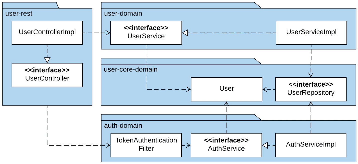
Figure 13.6 – User microservice
In the preceding diagram, we can once again see the clear separation of concerns between the business functionality provided by user-domain and the authentication functionality provided by auth-domain.
The refactored code can be found in this book's GitHub repository, in the Chapter 13 folder: https://github.com/PacktPublishing/Modernizing-Applications-with-Google-Cloud-Platform/tree/master/Chapter%2013.
When refactoring from banking-domain into account-domain, user-domain, and auth-domain, we also took the opportunity to remove classes that are no longer required because we are using firebase authentication instead of handling all the authentication, registration, and other self-service tasks ourselves. Our refactoring of banking-legacy-rest into account-rest and user-rest was much simpler but required some additional changes to enable each microservice to have its own database, as well as to be able to use the user database for authentication. We will cover that in the next section.
Refactoring the database
A key concept of microservices is that they are independent of each other. This means that they should have separate databases. However, we would not want each microservice to have a copy of the tables used for authentication as this would lead to an unhealthy quantity of duplicated data. It would also lead to the risk of the authentication data getting out of sync. For this reason, we need a way of using two separate databases in a single microservice. These are the database for the service and the database for authentication.
Fortunately, there is a way to accomplish this using Spring Boot by making changes only to our configuration code and not our implementation code.
Our configuration for persistence was as follows:
@Configuration
@EnableJpaRepositories(
basePackages = {"uk.me.jasonmarston.domain.repository"})
@EnableTransactionManagement
public class PersistenceConfig {
}
The preceding configuration class simply enabled Spring Boot JPA support in Spring Boot, specified where the repository interface could be found, and enabled transactions. What we need to do is replace the preceding class with two new classes to configure the two databases.
Let's examine the UserPersistenceConfig class:
@Configuration
@EnableJpaRepositories(
basePackages = {"uk.me.jasonmarston.domain.user.repository"},
entityManagerFactoryRef = "userEntityManagerFactory",
transactionManagerRef = "userTransactionManager")
@EnableTransactionManagement
public class UserPersistenceConfig {
@Autowired
private Environment env;
...
}
In the preceding configuration class, we have again enabled JPA support in Spring Boot and enabled transactions. This time, when we specified where the repository interfaces could be found, we were more specific and provided the location for the UserRepository interface. We also provided references to two beans that will be defined in this class: userEntityManagerFactory and userTransactionManager. We will get to these shortly.
The next thing we need to do is declare our userDataSource, as follows:
@Primary
@Bean(name = "userDataSource")
@ConfigurationProperties(prefix = "spring.datasource")
public DataSource userDataSource() {
return DataSourceBuilder.create().build();
}
Note that when declaring the preceding bean, we provided the @ConfigurationProperties annotation and specified that the properties found in application.properties that apply to this bean are the ones that start with spring.datasource. We also applied the @Primary annotation to indicate that this is the primary DataSource for Spring Boot, as Spring Boot always requires a primary DataSource.
Next, we will declare our userEntityManagerFactory bean, as follows:
@Primary
@Bean(name = "userEntityManagerFactory")
public LocalContainerEntityManagerFactoryBean userEntityManagerFactory(EntityManagerFactoryBuilder builder) {
Map<String, Object> properties = new HashMap<>();
properties.put("hibernate.hbm2ddl.auto", env.getProperty("spring.jpa.hibernate.ddl-auto"));
properties.put("hibernate.dialect", env.getProperty("spring.jpa.properties.hibernate.dialect"));
properties.put("hibernate.implicit_naming_strategy", env.getProperty("spring.jpa.hibernate.naming_strategy"));
return builder
.dataSource(userDataSource())
.packages(User.class, Authority.class)
.properties(properties)
.build();
}
There are a few things to unpack in the preceding code. Firstly, it makes use of the userDataSource bean we declared previously since an EntityManagerFactory must be linked to a DataSource. Secondly, rather than explicitly specifying packages, we listed the classes that are annotated with @Entity (Spring Boot will deduce the package from the class). Thirdly, we provided properties for EntityManagerFactory by mapping properties from our application.properties file into the ones required for a manually configured EntityManagerFactory. Finally, we declared this as the primary EntityManagerFactory by applying the @Primary annotation for the same reason we did with our userDataSource bean.
Important Note
The hibernate.hbm2ddl.auto property is needed if we want Spring Boot to automatically create and update the tables in our new databases. In production, this would not be necessary or a wise thing to do.
Finally, we will declare our userTransactionManager bean, as follows:
@Primary
@Bean(name = "userTransactionManager")
public PlatformTransactionManager userTransactionManager(
final @Qualifier("userEntityManagerFactory") LocalContainerEntityManagerFactoryBean userEntityManagerFactory) {
return new JpaTransactionManager(userEntityManagerFactory.getObject());
}
The method in the preceding code takes a LocalContainerEntityManagerFactoryBean as a parameter. We apply the @Qualifier annotation to the parameter to make sure our userEntityManagerFactory is injected by Spring Boot. Then, we create and return JpaTransactionManager, passing userEntityManagerFactory into the constructor. Once again, this bean is annotated with the @Primary annotation as Spring Boot needs a primary transaction manager.
Now, let's move on to the AccountPersistenceConfig class, as follows:
@Configuration
@EnableJpaRepositories(
basePackages = {"uk.me.jasonmarston.domain.account.repository"},
entityManagerFactoryRef = "accountEntityManagerFactory",
transactionManagerRef = "accountTransactionManager")
@EnableTransactionManagement
public class AccountPersistenceConfig {
@Autowired
private Environment env;
...
}
The preceding code is almost identical to the UserPersistenceConfig class. The differences shown previously are simply the location of the repository and the names of the beans to be used for EntityManagerFactory and TransactionManager.
The declaration of the three beans in this class are also almost identical to the ones in the UserPersistenceConfig class, so we will simply examine the differences, starting with accountDataSource:
@Bean(name = "accountDataSource")
@ConfigurationProperties(prefix="spring.account-datasource")
public DataSource accountDataSource() {
return DataSourceBuilder.create().build();
}
The differences here are the bean's name and the prefix for the configuration properties. We must have a separate set of configuration properties for DataSource as it connects to a separate database, so it will have a different URL, user ID, and password.
The differences in accountEntityManagerFactory are as follows:
@Bean(name = "accountEntityManagerFactory")
public LocalContainerEntityManagerFactoryBean accountEntityManagerFactory(EntityManagerFactoryBuilder builder) {
...
return builder
.dataSource(accountDataSource())
.packages(Account.class, Transaction.class)
.properties(properties)
.build();
}
In this case, we have named the bean accountEntityManagerFactory, we are using accountDataSource rather than userDataSource, and we are identifying the packages to scan by passing in the Account and Transaction classes.
We will finish by looking at the accountTransactionManager bean:
@Bean(name = "accountTransactionManager")
public PlatformTransactionManager accountTransactionManager(
final @Qualifier("accountEntityManagerFactory") LocalContainerEntityManagerFactoryBean accountEntityManagerFactory) {
return new JpaTransactionManager(accountEntityManagerFactory.getObject());
}
Again, the differences here are in the naming and references. Our bean is called accountTransactionManager and it uses the accountEntityManagerFactory bean.
The remaining difference is that none of the beans have the @Primary annotation as they are secondary rather than primary and we can only have one set of primary beans.
The last change we need to make is to application.properties, as follows:
# Primary datasource (User DataSource)
spring.datasource.jdbcUrl = ${USER_DATASOURCE_URL}
spring.datasource.username = ${USER_DATASOURCE_USERNAME}
spring.datasource.password = ${USER_DATASOURCE_PASSWORD}
spring.datasource.driverClassName=com.mysql.jdbc.Driver
# Account DataSource
spring.account-datasource.jdbcUrl = ${ACCOUNT_DATASOURCE_URL}
spring.account-datasource.username = ${ACCOUNT_DATASOURCE_USERNAME}
spring.account-datasource.password = ${ACCOUNT_DATASOURCE_PASSWORD}
spring.account-datasource.driverClassName=com.mysql.jdbc.Driver
The preceding changes provide the configuration needed for our separate databases.
We will need to create these databases and users and grant each user access to the appropriate database in Google Cloud SQL using the MySQL command-line tooling, as we covered in Chapter 11, Re-platforming the Data Layer.
Now that we have learned how the backend is refactored into microservices, we can move on and look at what changes are needed in the frontend.
The web frontend
The changes needed in the frontend are minimal and constrained to the two service modules we create to wrap around the REST endpoints. We simply remove banking/ from the start of all the relative URLs. While this is not strictly necessary, it does remove the suggestion that there is some sort of hierarchy in place with the REST services – they are simply endpoints.
Now, you may be wondering, if we are going to deploy the Spring Boot applications potentially on separate hosts, but definitely as separate deployment units, how do those URLs relative to the host of our frontend get mapped to those backend services?
As you will see in the next section, we will be hosting the frontend in NGINX, which is a high-performance web server and reverse proxy. We will be making use of the reverse proxy's functionality to map those URLs to the actual URLs and proxy the requests. Precisely how this will be implemented will depend on which platform we chose for deployment; that is, either Google Kubernetes Engine, Google App Engine (Flexible), or Google Cloud Run.
Whichever platform we use, the result will be updating the /etc/NGINX/conf.d/default.conf configuration file. The updated file will look something like this:
server {
listen 80;
server_name localhost;
location / {
root /usr/share/NGINX/html;
index index.html;
}
location /account {
proxy_pass http://<account_host_mapping>:8080
}
location /user {
proxy_pass http://<user_host_mapping>:8080
}
}
The preceding configuration tells NGINX that it should listen on port 80, serve web content from /user/share/NGINX/html by default, proxy to the account microservice on URLs starting with /account, and to the user microservice on URLs starting with /user.
The values for <account_host_mapping> and <user_host_mapping> will depend on the deployment option selected, as will the method for updating this file.
This mapping of local URLs and proxying to the actual microservices is how we implement the Strangler Facade from the Strangler Pattern. If we still had most of the service endpoints in a monolith, we would use the appropriate proxy statements to send all the requests, not split them into microservices and send them to the original monolith. Now, we will look a little more closely at the Strangler Pattern.
The Strangler Pattern revisited
We looked at the Strangler Pattern in Chapter 12, Designing the Interim Architecture. In that chapter, we looked at the different stages in the refactoring journey of using the Strangler Pattern. The following diagram shows the start of our journey:

Figure 13.7 – Monolithic application
In the preceding diagram, we have the initial state with no Strangler Facade in play. The entire application is in our banking-mvc project, which is deployed as a JAR or WAR file.
The following diagram shows the first steps of refactoring toward microservices by breaking out the frontend from the backend:

Figure 13.8 – Initial Strangler stage
In the preceding diagram, we have our frontend, which is our front-end project that holds all the static content for our web application. These are the stylesheets, JavaScript, HTML, and images needed for the user interface. We also have our backend, which is our banking-rest project, which contains all the rest services and domain classes for our banking application. Between the two, we have our Strangler Facade, which means that as we make changes and separate the microservices, the frontend will be completely unaware of these changes. We will examine the options for the Strangler Facade in the next few sections.
In the following diagram, we can see the final stage of our refactoring, which is using the Strangler Pattern and applying the Strangler Facade:

Figure 13.9 – Final Strangler stage
In the preceding diagram, our backend monolith of banking-rest has been replaced with two microservices, user-rest and account-rest. front-end is completely unaware of the change as the backend microservices and before that, the backend monolith is behind the Strangler Facade.
We will look at three options regarding how we will implement the Strangler Facade. The options we will examine are as follows:
- Google HTTP(s) Load Balancer Routing
- Google App Engine Dispatcher
- Apigee API Manager
In the next few sections, we will take a brief look at each of the options, starting with Google HTTP(s) Load Balancer Routing.
Google HTTP(S) Load Balancer Routing
With Google HTTP(S) Load Balancer in Google Cloud, we can make use of content-based load balancing, which routes requests to backend services based on the path of the HTTP(S) request. This is an extremely simple and flexible approach to implementing a Strangler Facade that works with both Google Compute Engine and Google Kubernetes Engine. We define a set of rules, and each rule says that if the URL matches this pattern, send the request to that service. We will be using this approach in Chapter 16, Orchestrating Your Application with Google Kubernetes Engine.
This approach does not work for Google App Engine, so we need to look at Google App Engine Dispatcher, which is covered in the next section.
Google App Engine Dispatcher
Unsurprisingly, Google App Engine Dispatcher works very much like the HTTP(S) Load Balancer approach. This solution is restricted to only being used with Google App Engine and maps our HTTP(S) URL paths to services deployed in Google App Engine. We define a set of rules, and each rule says that if the URL matches this pattern, send the request to that service. We will be using this approach in Chapter 17, Going Serverless with Google App Engine.
This just leaves us with the final common approach, Apigee, which is covered in the next section.
Apigee API Manager
The Apigee approach is where you use the API Gateway features of Apigee. This is usually done if you expect to have multiple applications exposing APIs rather than just a few APIs in a single application. API management solutions such as Apigee don't just offer an API Gateway, but also provide support for applying policies to transform, secure, and rate limit API usage. It also offers monitoring and development portal support. This is a much richer set of features than is needed for a simple application of the Strangler Facade, and it costs a significant amount more than using the other features. For these reasons, we will not use Apigee in this book. Instead, we will note that it is a valid solution and a great one when we are dealing with more than one application.
We will now learn how we can containerize our deployment units using Docker and add them to Google Cloud Build.
Containerizing the deployment units with Docker
The three deployment options we will be studying in the final three chapters of this book are Google Kubernetes Engine, Google App Engine (Flexible), and Google Cloud Run. All these options are container-based, so we need to understand how to define a Docker image, how to build that image, and how to push it into a container registry.
We will begin by examining how we do this for our front-end project. The following source will be placed in a file called Dockerfile, at the root of our frontend project:
FROM NGINX:1.17.10-alpine
COPY WebContent /usr/share/NGINX/html
EXPOSE 80
The preceding code starts by declaring our image. This will build on top of the NGINX version 1.17.10-alpine image, which can be found in the Docker registry. We then copy our web content into the directory NGINX uses to serve web content, specifically /usr/share/NGINX/html. We finish by declaring that the container will expose a service on port 80.
It is important to understand that Docker images are made up of layers. Each layer adds on top of the previous layer and when taken together, they form an entire image. In the preceding file, the FROM, COPY, and EXPOSE commands define a layer in the Docker image. This layering improves deployment times as only changed layers need to be pushed to the container registry and transferred to the deployment environment.
So, how do we get from a Dockerfile to a Docker image and have that pushed to a container registry? We will be using Google Cloud Build for this, as shown in the following cloudBuild.yaml file:
steps:
- name: 'gcr.io/cloud-builders/docker'
args: ['build', '-t', 'gcr.io/$PROJECT_ID/front-end', '.']
dir: 'front-end'
- name: 'gcr.io/cloud-builders/docker'
args: ['push', 'gcr.io/$PROJECT_ID/front-end']
dir: 'front-end'
In the preceding cloudBuild.yaml file, we are making use of the Docker cloud builder. The build is broken into two steps. The first step builds our image and tags it with gcr.io/$PROJECT_ID/front-end. The $PROJECT_ID part of the tag is a substitution variable and is provided by Google Cloud Build to identify which project the build is running in. It will be replaced by the actual project ID at build time. The second step pushes our newly built and tagged image to the Google Container Registry using that tag.
Now, let's look at the Dockerfile for our user-rest project. The account-rest project follows the same pattern, so we will not examine that project here:
FROM openjdk:8-jdk
ARG JAR_FILE=build/libs/user-rest-*.jar
COPY ${JAR_FILE} app.jar
RUN mkdir /credentials
EXPOSE 8080
ENTRYPOINT ["java","-jar","/app.jar"]
This time, we are using openjdk version 8-jdk as the base image we will build upon. We create an ARG, which is a variable to be used in our build of the Docker image. The JAR_FILE variable is set to the name of our JAR file from the gradle build. The name of this JAR includes the version number, which is why we used a wildcard in the name. The next statement copies the JAR file into our image and renames it app.jar. We then create a folder called /credentials, which will be used as a mount point later to expose the credential files for our service accounts. We declare that the service will be exposed on port 8080 and finally set the ENTRYPOINT property of our container to java -jar /app.jar. This tells the container that when it is started, this is the command that will be executed.
We will cover how the credential files and the environment variables get injected into our container in each of the final three chapters, as this depends on the deployment choices we make.
Now, let's turn our attention to the cloudBuild.yaml file for our user-rest project:
steps:
- name: 'gcr.io/cloud-builders/gradle'
args: ['bootJar']
env:
- 'artifactory_contextUrl=${_ARTIFACTORY_URL}'
- 'artifactory_password=${_ARTIFACTORY_PASSWORD}'
- 'artifactory_user=${_ARTIFACTORY_USER}'
dir: 'user-rest'
- name: 'gcr.io/cloud-builders/docker'
args: ['build', '-t', 'gcr.io/$PROJECT_ID/user-rest', '.']
dir: 'user-rest'
- name: 'gcr.io/cloud-builders/docker'
args: ['push', 'gcr.io/$PROJECT_ID/user-rest']
dir: 'user-rest'
The preceding cloudBuild.yaml file has three build steps. The first step uses the Gradle Cloud Builder and is set up mostly the same as what we had previously in our banking-legacy-rest project. The major difference in this step from our previous one is that we are using the bootJar task rather than the bootWar task. This is because we are building a standalone Spring Boot application as a JAR file with an embedded servlet container, rather than a WAR file to be deployed into a servlet container. The final two tasks build our image and push it to the Google Container Registry, as we did with the front-end project.
One of the great things about using Google Cloud Build is that we don't have to install and configure Docker or other tools needed to perform builds in our local environment, but instead use the secure environments provided by Google, which maintain those tools and install them.
To enable automation for all this, we will need to create new build triggers for our new projects – account-rest, account-domain, user-rest, user-domain, user-core-domain, and auth-domain – and delete the triggers for the old projects; that is, banking-legacy-rest and banking-domain. Then, we must replace our current local Git repository for our Cloud Source Repository with the projects from the Chapter 13 folder of this book's GitHub repository and then add, commit, and push all the changes (including deletions).
With that, we have learned how to define a Docker image, how to build that image, and how to push it to Google Container Registry using Google Cloud Build.
Summary
In this chapter, we examined the packaging structure of our application and analyzed the services and dependencies in our banking-legacy-rest and banking-domain projects. We realized that UserService was not following the single responsibility principle and had two distinct responsibilities: user profiles and authentication. Based on this, we refactored the authentication responsibilities of UserService in AuthService, placing AuthService into its own project, along with TokenAuthenticationFilter. As both UserService and AuthService depend on User and UserRepository, we also placed User and UserRepository into their own project called user-core-domain. This allowed us to separate our concerns into two microservices, user-rest and account-rest. We then learned how to use two separate databases in our microservices to enable us to have a separate database for each microservice, as well as a shared database for authentication. Finally, we learned how to define container images using a Dockerfile, build the image using Google Cloud Build, and push the image to Google Container Registry using Google Cloud Build.
In the next chapter, we will learn how to refactor the frontend and expose the backend with REST services