
Chapter 9: The Initial Architecture on Google Compute Engine
We will now take our first step toward modernizing our application by moving it to the cloud. In this chapter, we will not be making any changes to the application itself, but instead we will be looking at the absolute minimum infrastructure architecture needed to run the application on Google Cloud. Once we have our initial architecture, we will then go step by step through implementing the architecture on Google Cloud using the Google Cloud Console.
In this chapter, we will cover the following:
- The initial infrastructure design
- Creating the modernization project
- Implementing the network
- Implementing the Virtual Machines (VMs)
- Importing the data
Technical requirements
In order to follow along and implement the steps in this book, you will need to have the following:
- An internet domain where you are the owner and can manage the Domain Name Service (DNS) records
- A Google Cloud account (a free trial account is fine)
- To have signed up to Cloud Identity (the free tier is fine) from the Google Cloud Console (using your internet domain)
- To have set up an organization to be the root of your structure in Google Cloud
The initial infrastructure design
Our starting point will be the legacy infrastructure architecture illustrated in Figure 9.1:

Figure 9.1 – Legacy infrastructure architecture
The key elements from this architecture that we need to consider for our initial rehosting are as follows:
- The network
- The network security
- The VMs
Before we begin to design our infrastructure architecture, there are a few Google Cloud terms that we need to define as they are key to understanding how Google Cloud is organized, and where we will place our resources. A resource in Google Cloud is classified as a global resource, regional resource, or zonal resource:
- Global resource: A resource that is not restricted to a specific region or zone within a region but is hosted in multiple locations worldwide.
- Region: A geographic location where we can host our Google Cloud resources. Examples of this are US-WEST1 and EUROPE-WEST1. A list of available regions and zones can be found at https://cloud.google.com/compute/docs/regions-zones#available. Choosing which region to use is often based on proximity to our users or applicable regulations such as the General Data Protection Regulation (GDPR).
- Zone: A specific location within a region. Each region has more than one zone, and each zone is physically separate from the others in the region. This separation is to provide isolated failure domains for each zone. Examples of zone names are EUROPE-WEST1-C and EUROPE-WEST1-D. The convention for naming zones is <region>-<zone>. In our example, we have zones C and D in region EUROPE-WEST1.
- Regional resource: A resource that is available only to other resources in the same region. An example of this is a static public IP address that can be assigned to any of the VMs in the same region as the address.
- Zonal resource: A resource that is available only to other resources in the same zone. An example of this is a disk. These can only be accessed by a VM in the same zone.
Now we understand global, regional, and zonal resources, we can begin to map out our infrastructure architecture.
Designing our network
In Google Cloud, our network is provided by a Virtual Private Cloud (VPC). This is a virtualized version of a physical network. A VPC is a global resource meaning it is not associated with a specific region or zone. When we create a project in Google Cloud a default VPC is provisioned for us automatically. This VPC has a subnet automatically provisioned for every Google Cloud region available. A subnet is a regional resource so cannot be in more than one region but is available to every zone in its region. In a production scenario we would not use the default VPC, but instead specify and configure a VPC based exactly on what we need in terms of zones and IP address ranges. For the purposes of our modernization journey, we will use the default VPC.
Our next step is to decide which region we will be using. As I am based in the UK, I chose europe-west2 as that region is hosted in the UK. Choose a region that is close to you in order to minimize latency. Finally, we pick a zone to place our VMs in (remember that VMs are an example of a zonal resource). In this case we have chosen europe-west2-c.
These choices mean we have the following start to our infrastructure architecture, shown in the following figure depicting the initial infrastructure architecture (network):

Figure 9.2 – Initial infrastructure architecture (network)
Now we have made our decisions on which region and zone we will be working in; we can continue onward and consider what VMs we will provision. From Figure 9.1, we can identify that we will need a minimum of three VMs. At this point, we are not considering concerns such as availability, we are just looking at the minimum to get our functionality running in Google Cloud..
The VMs we will need are as follows:
- A VM to run a Tomcat server
- A VM to host MySQL as our persistent data store
- A VM to host Redis to handle our application sessions
Adding these VMs to our infrastructure architecture gives us the following:

Figure 9.3 – Initial infrastructure architecture (VMs)
As this is development rather than production, we will initially give all the VMs public IP addresses. In production, this would be a serious security issue and must not be done. We are keeping things simple to focus on the actual modernization tasks and we have no private or confidential data at risk. For serious development, we would use either a VPN to access the VMs or create a Bastion host for the same purpose.
Now we have our network and VMs identified and added to our architecture. What next?
Designing our network security
Although we are giving every VM a public IP address, we will still need to implement some network security. The focus here will be on the network security for the application rather than our administration of the VMs. We will be making use of Google Cloud firewall rules.
This is a global service provided by Google Cloud and allows us to filter traffic based on the following:
- IP address ranges
- Network tags
- Service accounts
- Protocols and ports
Rules can be applied to ingress (incoming) and egress (outgoing) traffic, and either allow or deny traffic that matches the given rule.
Our rules from our legacy application state the following:
- All inbound traffic from the internet is blocked except for HTTP(S) traffic to the Tomcat servers.
- All inbound traffic to the Redis server is blocked except for the Tomcat servers using the Redis server on the standard port, which is 6379.
- All inbound traffic to the MySQL server is blocked except for the Tomcat servers using the MySQL server on the standard port, which is 3306.
As we are working in a learning sandbox, we will leave the default rule provided by Google Cloud in place that allows ingress to all VMs from any address to SSH. Again, we cannot stress enough that this is not recommended for production environments.
Now that we have taken firewalls into consideration, we have the final version of our initial infrastructure architecture laid out, which we will continue to build on in the rest of this book. The following diagram depicts that initial infrastructure and network architecture:
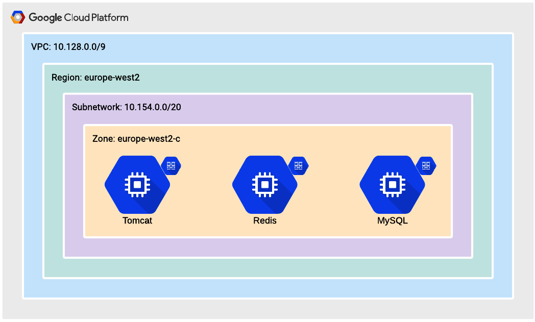
Figure 9.4 – Initial infrastructure architecture
Now that an initial network architecture has been created, let's plan to create the modernization Google Cloud project.
Creating the modernization project
Before we start building out our architecture in Google Cloud we need to set up the structure for our account. At the root of the structure, we have the organization we created when we set up Cloud Identity for Identity and Access Management (IAM). An account can have only one organization. The organization can contain folders and/or projects. A folder can contain folders or projects. This provides us with a tree structure for organizing our resources, called the resource hierarchy.
The purpose of our resource hierarchy is to do the following:
- Provide an ownership hierarchy, often reflecting the structure of the enterprise and cost centers.
- Provide a structure for inheriting access control and policies.
For our organization, we will keep things simple and create a folder called modernization and within that folder a project called BankingApplication. Our resource hierarchy will then look like this:

Figure 9.5 – Initial resource hierarchy
A more realistic resource hierarchy for an enterprise may look like this:
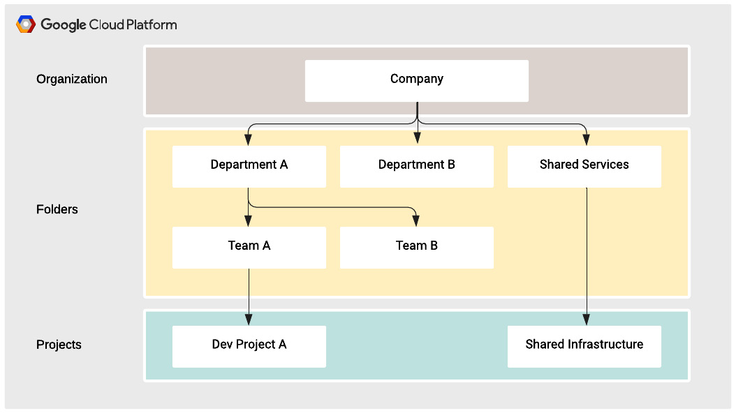
Figure 9.6 – Example resource hierarchy
Now we have defined our resource hierarchy, we will create it in Google Cloud using the following steps:
- From the Google Cloud Console at https://console.cloud.google.com, click the navigation menu button in the top left of the window:

Figure 9.7 – Navigation menu button
- In the navigation menu, select IAM & admin | Manage Resources:

Figure 9.8 – IAM & admin menu
- You will now see the resource hierarchy. Click the Create Folder button at the top of the window:

Figure 9.9 – Create folder button
- You will now see the New Folder form. Enter the name you want to give to your folder, ensure the Location field is set to your organization, and click Create:
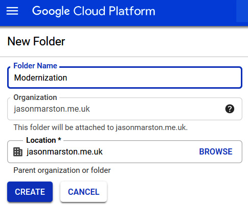
Figure 9.10 – New folder form
- Your folder has now been created and you have been returned to the Manage Resources page. Click CREATE PROJECT:

Figure 9.11 – CREATE PROJECT button
- You will now see the New Project form. Enter the name you want to give to your project, ensure Location is set to the folder you created in the previous step, and click Create:

Figure 9.12 – New Project form
Now that we have established our resource hierarchy and created our project, we can begin implementing our infrastructure architecture.
Implementing the network
We described earlier in this chapter how when a project is created, a default VPC is automatically created for us. This means we can simply reuse that VPC for our modernization work. What remains to be done is implementing the firewall rules we defined previously. To recap, the rules are as follows:
- All inbound traffic from the internet is blocked except for HTTP(S) traffic to the Tomcat servers.
- All inbound traffic to the Redis server is blocked except for the Tomcat servers using the Redis server on the standard port, which is 6379.
- All inbound traffic to the MySQL server is blocked except for the Tomcat servers using the MySQL server on the standard port, which is 3306.
We will now implement these firewall rules using the following steps:
- In the navigation menu, select VPC network | Firewall rules:

Figure 9.13 – VPC network menu
- Ensure that at the top of the window, your project is selected:

Figure 9.14 – Project selection dropdown
You will now see the default rules that are allocated to our project:

Figure 9.15 – Default firewall rules
- The first rule we will implement is to allow incoming traffic on ports 80 and 443 to our Tomcat servers. Click CREATE FIREWALL RULE:

Figure 9.16 – CREATE FIREWALL RULE button
- You will now see the Create a firewall rule form. Enter the following and click Create:
a) Name: A unique name for your firewall rule. In this case, we'll use allow-http-https.
b) Network: default(in new line L-regular)
c) Priority: 1000
d) Direction of traffic: Ingress
e) Action on match: Allow
f) Targets: Specified target tags
g) Target tags: web
h) Source filter: IP ranges
i) Source IP ranges: 0.0.0.0/0
j) Protocols and ports: Specified protocols and ports
k) Select tcp and enter 80 and 443:

Figure 9.17 – Create a firewall rule form
- Repeat the preceding process with the following details to create the rule to allow the Tomcat server to communicate with the Redis server:
a) Name: allow-redis
b) Network: default
c) Direction of traffic: Ingress
d) Action on match: Allow
e) Targets: Specified target tags
f) Target tags: redis
g) Source filter: Source tags
h) Source tag: web
i) Protocols and ports: Specified protocols and ports
j) Select tcp and enter 6379
- Repeat the preceding process with the following details to create the rule to allow the Tomcat server to communicate with the MySQL server:
a) Name: allow-mysql
b) Network: default
c) Direction of traffic: Ingress
d) Action on match: Allow
e) Targets: Specified target tags
f) Target tags: mysql
g) Source filter: Source tags
h) Source tag: web
i) Protocols and ports: Specified protocols and ports
j) Select tcp and enter 3306
- Finally, we delete the rule that allows all internal traffic on all ports. Select the default-allow-internal rule and click DELETE:

Figure 9.18 – Delete firewall rule
- Click DELETE to confirm you want to delete the default-allow-internal firewall rule:

Figure 9.19 – Confirm the deletion of the firewall rule
Let's summarize what we have just done:
- We decided to use the default VPC that was automatically created when we created our project.
- We created a firewall rule to allow inbound HTTP(S) traffic to our Tomcat server.
- We created a firewall rule to allow inbound Redis traffic to our Redis server from our Tomcat server.
- We created a firewall rule to allow inbound MySQL traffic to our MySQL server from our Tomcat server.
- We deleted the default firewall rule that allowed all inbound traffic for all internal IP addresses.
In the next section, we will implement our VMs, applying the tags we referenced in our firewall rules to enable the required communications for our application.
Implementing the VMs
Now we get to the core of this chapter: implementing our VMs. We will build these up manually and create them using the Google Cloud Console. A later chapter will cover automation and creating a CI/CD pipeline in order to enable DevOps.
We will start at the backend of the solution and move forward. There are two backend services in our solution, sessions and persistence. As we must choose one or the other, we will start with persistence, meaning our MySQL database.
As we want to make as few changes as possible, and not have to install software if we can avoid it, we will make use of the Google Cloud Marketplace. Specifically, we will use the MySQL certified by Bitnami image from the Marketplace.
This VM image comes with MySQL preinstalled and is set up to minimize costs for a development environment. It is well suited for the purpose of learning about modernization.
We will create and configure the MySQL VM using the following steps:
- In the navigation menu, select Marketplace:

Figure 9.20 – Marketplace menu item
- In the search field on the Marketplace page, enter MySQL Certified by Bitnami and hit Enter:
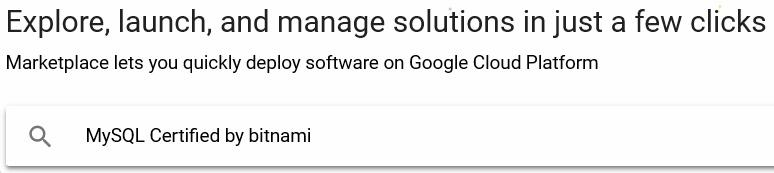
Figure 9.21 – Marketplace search
- Select MySQL Certified by Bitnami from the list:

Figure 9.22 – MySQL in the Marketplace search results
- Click LAUNCH ON COMPUTE ENGINE:

Figure 9.23 – Launch the Bitnami image on Compute Engine
- Enter mysql for Deployment name, and select europe-west2-c for Zone:

Figure 9.24 – Name and zone for MySQL VM
- Tick the I accept the GCP Marketplace Terms of Service box and click Deploy:
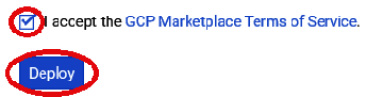
Figure 9.25 – Deploy the MySQL VM
- This deployment will take a few minutes to finish. Make a note of the key information given by the deployment, specifically, the Admin user and Admin password values:
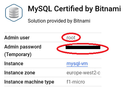
Figure 9.26 – Admin user and admin password
- Once the VM has finished provisioning, we use SSH to perform administration tasks in the VM. Click SSH:

Figure 9.27 – SSH button for access to the VM
- Now we need to ensure all the software is up to date, as changes may have been released since the image was placed on the marketplace. Let's do this by entering the following command:
sudo apt-get -y update
Next, we will change the password we recorded in the previous step 7. To do this we need to log in to the MySQL server from our SSH session following the steps:
- Enter the following command:
mysql -u root -p
- When prompted, enter the password we recorded previously. Enter the following commands to change the password (where <yournewpassword> is the password you have chosen):
alter user '''root''@''localhost' 'localhost'' identified by ''<yournewpassword>'';
flush privileges;
quit
Log in again using the command from step 1 and your new password to ensure this has worked. At this point, we have an empty MySQL server ready to configure as needed for our application.
- We will now create our empty database and the user our application will utilize to access the database, and grant our user authority over the database, by entering the following commands in our MySQL session:
create database banking;
create user ''bankinguser''@''%'' identified with mysql_native_password by ''<newpassword>'';
grant all on banking.* to ''bankinguser''@''%'';
With the preceding commands we did the following:
a) Created the database.
b) Created our user with the name bankinguser, allowed access from any host using the % location, and set <newpassword> as the password. In production, we would lock down the location more precisely. Please be sure to record the password.
c) Granted our user all authorizations on the banking database. In production, we would not need all authorizations, but as we are in development, our application will create the database artifacts (schemas, tables, and others) as needed.
The final step in setting up this server is to apply our firewall rule. We will do this by adding the mysql tag to the VM. As we used the marketplace image for the MySQL server, a tag has already been added, but it is important to understand how to add network tags to our servers, hence we will do this, even though if we had used the tag provided by the marketplace, we would not have needed to do this.
To apply the mysql tag, follow the steps:
- In the navigation menu, select Compute Engine:

Figure 9.28 – Compute Engine menu item
- Click mysql-vm on the VM Instances page to open the VM instance details page:

Figure 9.29 – VM instances page
- Click EDIT:

Figure 9.30 – Edit VM instance button
- Scroll down to the Network tags section and enter mysql:

Figure 9.31 – Network tags
- Scroll to the bottom of the page and click Save.
That completes the provisioning and configuration of our MySQL VM. We have prepared the database for our application and applied the mysql tag to allow for communication between the Tomcat server and the MySQL server.
Now we will create our Redis VM. The steps already explained previously will not be repeated in detail for this VM:
- Using the marketplace, provision a VM using the Redis certified by Bitnami deployment. Enter redis for Deployment name and select europe-west2-c for Zone. Remember to make a record of the username and password.
- Apply the redis tag to the network tags section of the VM instance details page.
- Once the VM has deployed and started, connect to it via SSH and enter the following commands, where <CURRENTPASS> is the password we recorded earlier, and <NEWPASS> is the password we have chosen:
sudo apt-get -y update
redis-cli -h redis-vm
AUTH <CURRENTPASS>
CONFIG SET requirepass <NEWPASS>
AUTH <NEWPASS>
Finally, we will create our Tomcat VM. The steps already explained will not be repeated in detail for this VM:
- Using the marketplace, provision a VM using the Tomcat certified by Bitnami deployment. Enter tomcat for Deployment name and select europe-west2-c for Zone. Remember to make a record of the username and password.
- Apply the web tag to the network tags section of the VM instance details page.
- In the VM instances details page, change Virtual Machine to use a static public IP address by clicking Create IP address:
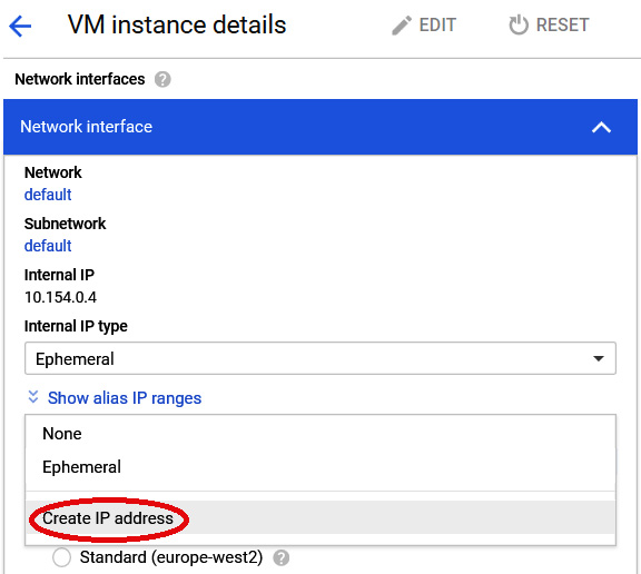
Figure 9.32 – Create IP address
- Provide a name for the IP address and click RESERVE:

Figure 9.33 – Reserve a static IP address
- On the VM instance details page, save your changes by clicking Save.
- Add records to your domain using the IP address. We used www.banking.jasonmarston.me.uk with the address 35.189.84.60, and banking.jasonmarston.me.uk with the same address. Note that how this is done will depend on your provider. (It may take a few minutes for the changes to propagate.)
- In the Tomcat VM, set up the SSL certificate for these hosts using the Bitnami HTTPS configuration tool, which obtains certificates from Let's Encrypt. Enter the following command and responses to set this up. Note that we have removed most of the informational text and just focused on the questions and responses (replace the domain names with the one you used):
sudo /opt/bitnami/bncert-tool
Domain list []: www.banking.jasonmarston.me.uk banking.jasonmarston.me.uk
Enable HTTP to HTTPS redirection [Y/n]: ny
Enable non-www to www redirection [Y/n]: n
Enable www to non-www redirection [y/N]: ny
Do you agree to these changes? [Y/n]: y
E-mail address []: [email protected]
Do you agree to the Let's Encrypt Subscriber Agreement? [Y/n]: y
Press [Enter] to continue:
- Configure the application by connecting to the Tomcat VM via SSH and add the following content to the end of the /opt/bitnami/tomcat/bin/setenv.sh file. We will start with the MySQL configuration details, such as hostname, username, and administration:
# MySQL Configuration
export BANKING_DATASOURCE_DDL_AUTO="update"
export BANKING_DATASOURCE_DIALECT="org.hibernate.dialect.MySQL5Dialect"
export BANKING_DATASOURCE_PASSWORD="<YOUR_MYSQL_PASSWORD>"
export BANKING_DATASOURCE_URL="jdbc:mysql://mysql-vm.europe-west2-c:3306/banking?useSSL=false&allowPublicKeyRetrieval=true"
export BANKING_DATASOURCE_USERNAME="bankinguser"
# Hostname for use in emails
export BANKING_HOST_NAME="<YOUR_FULLY_QUALIFIED_DOMAIN_NAME>"
# Administration user configuration
export BANKING_INITIAL_ADMIN_CONTEXT_PATH="/"
export BANKING_INITIAL_ADMIN_EMAIL="<YOUR_EMAIL_ADDRESS>"
export BANKING_INITUAL_ADMIN_PASSWORD="<YOUR_INITIAL_PASSWORD>"
We will continue with the configuration for logging, email, environment, and Redis:
# Logging configuration
export BANKING_LOGGING_LEVEL="WARN"
# Email Configuration
export BANKING_MAIL_AUTH="true"
export BANKING_MAIL_FROM="noreply@<YOUR_DOMAIN>"
export BANKING_MAIL_HOST="<YOUR_SMTP_SERVER>"
export BANKING_MAIL_PASSWORD="<YOUR_SMTP_PASSWORD>"
export BANKING_MAIL_PORT="<YOUR_SMTP_PORT>"
export BANKING_MAIL_SOCKET_FACTORY="javax.net.ssl.SSLSocketFactory"
export BANKING_MAIL_STARTTLS="false"
export BANKING_MAIL_USERNAME="<YOUR_SMTP_USERNAME>"
# Environment configuration
export BANKING_PROFILES_ACTIVE="DEV"
# Redis configuration
export BANKING_REDIS_HOST="redis-vm.europe-west2-c"
export BANKING_REDIS_PORT="6379"
export BANKING_REDIS_PASSWORD="<YOUR_REDIS_PASSWORD>"
The preceding configuration does the following:
a) Informs the application that we are using MySQL as the relational database, and how to connect to it
b) Sets the logging level to WARN (we can change this to INFO or DEBUG if we need more detailed logging)
c) Provides the details of our initial administration user for the application
d) Provides the information needed to send emails from the application
e) Specifies that this is a development environment
f) Provides the details on how to connect to Redis
- Download the ROOT.war file from https://github.com/PacktPublishing/Modernizing-Applications-with-Google-Cloud-Platform/tree/master/Chapter%2009.
- From your SSH session, upload the ROOT.war file:

Figure 9.34 – Upload file
- Select ROOT.war from your local drive:

Figure 9.35 – The local ROOT.war file
- Once the file has uploaded, delete all the default applications deployed to Tomcat:
sudo rm -rf /opt/bitnami/tomcat/webapps/*
- Copy ROOT.war from your home directory in the Tomcat VM to the webapps directory:
sudo cp ~/ROOT.war /opt/bitnami/tomcat/webapps
- Make sure the .war file is owned by tomcat:
sudo chown tomcat:tomcat /opt/bitnami/tomcat/webapps/ROOT.war
Now you have deployed the application and, in a few minutes, you can test it using the fully qualified domain name you set up earlier. In my case, the custom domain I set up was www.banking.jasonmarston.me.uk.
Once that is completed, we need to ensure the database is updated appropriately.
Importing the data
The goal now is to create an applicable table in the database and the rows associated with that table. The necessary files are provided in the repository:
sudo mysqldump –add-drop-table -u root -p banking > banking.sql
Copy the file to the destination server:
mysql -u root -p banking < banking.sql
Then follow the earlier steps to make sure that bankinguser exists and has the correct permissions.
Summary
In this chapter, we looked at the infrastructure architecture of our legacy application and designed a simple initial infrastructure architecture for moving the application into the Google cloud. We decided that there would be no changes to the application code base, and we would only be changing the infrastructure. The infrastructure architecture did not address concerns such as scalability or availability, but instead focused on hosting our functionality and on network security between the layers of our application.
We then created our organizational structure and the project we will be working on throughout this book. Next, we implemented the firewall rules and the three VMs using the Marketplace. Then, we introduced persistence with a MySQL VM, sessions storage using the Redis VM, and an application web server with the Tomcat VM. Finally, we deployed our application and performed a basic test to see if we could access it.
In the next chapter, we will continue to refine our infrastructure architecture. Specifically, we will start to address concerns such as scalability and availability by making use of Google Cloud features such as zones and load balancers.