
9
COMMON UPPER-LAYER PROTOCOLS

In this chapter, we’ll continue to examine the functions of individual protocols, as well as what they look like when viewed with Wireshark. We’ll discuss five of the most common upper-layer (layer 7) protocols: DHCP, DNS, HTTP, and SMTP.
Dynamic Host Configuration Protocol (DHCP)
In the early days of networking, when a device wanted to communicate over a network, it needed to be assigned an address by hand. As networks grew, this manual process quickly became cumbersome. To solve this problem, Bootstrap Protocol (BOOTP) was created to automatically assign addresses to network-connected devices. BOOTP was later replaced with the more sophisticated Dynamic Host Configuration Protocol (DHCP).
DHCP is an application-layer protocol responsible for allowing a device to automatically obtain an IP address (and addresses of other important network assets, such as DNS servers and routers). Most DHCP servers today also provide other parameters to clients, such as the addresses of the default gateway and DNS servers in use on the network.
DHCP Packet Structure
DHCP packets can carry quite a lot of information to a client. As shown in Figure 9-1, the following fields are present within a DHCP packet:
OpCode Indicates whether the packet is a DHCP request or a DHCP reply
Hardware Type The type of hardware address (10MB Ethernet, IEEE 802, ATM, and so on)
Hardware Length The length of the hardware address
Hops Used by relay agents to assist in finding a DHCP server
Transaction ID A random number used to pair requests with responses
Seconds Elapsed Seconds since the client first requested an address from the DHCP server
Flags The types of traffic the DHCP client can accept (unicast, broadcast, and so on)
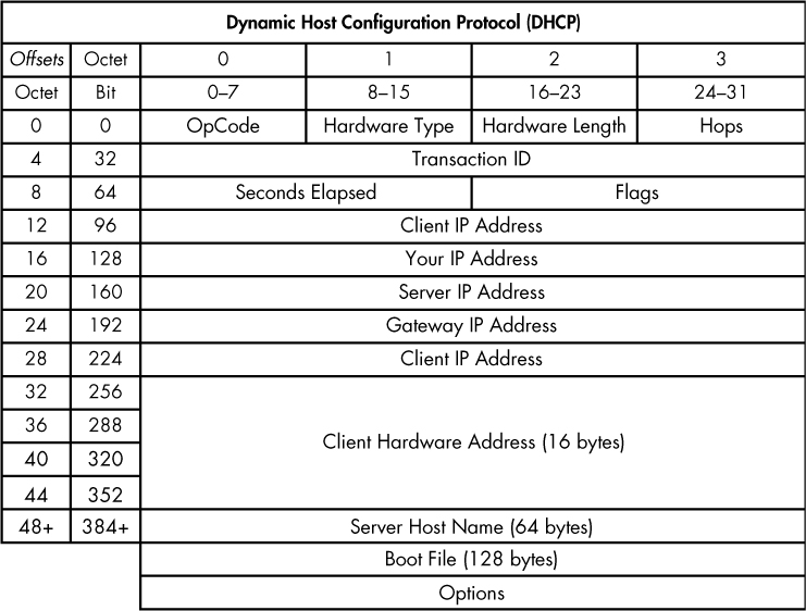
Figure 9-1: The DHCP packet structure
Client IP Address The client’s IP address (derived from the Your IP Address field)
Your IP Address The IP address offered by the DHCP server (ultimately becomes the Client IP Address field value)
Server IP Address The DHCP server’s IP address
Gateway IP Address The IP address of the network’s default gateway
Client Hardware Address The client’s MAC address
Server Host Name The server’s host name (optional)
Boot File A boot file for use by DHCP (optional)
Options Used to expand the structure of the DHCP packet to give it more features
The DHCP Initialization Process
dhcp_nolease _initialization.pcapng
The primary goal of DHCP is to assign addresses to clients during the initialization process. The renewal process takes place between a single client and a DHCP server, as shown in the file dhcp_nolease_initialization.pcapng. The DHCP initialization process is often referred to as the DORA process because it uses four types of DHCP packets: discover, offer, request, and acknowledgment, as shown in Figure 9-2. Here, we’ll take a look at each type of DORA packet.
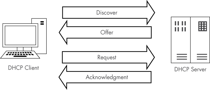
Figure 9-2: The DHCP DORA process
The Discover Packet
As you can see in the referenced capture file, the first packet is sent from 0.0.0.0 on port 68 to 255.255.255.255 on port 67. The client uses 0.0.0.0 because it does not yet have an IP address. The packet is sent to 255.255.255.255 because this is the network-independent broadcast address, thus ensuring that this packet will be sent out to every device on the network. Because the device doesn’t know the address of a DHCP server, this first packet is sent in an attempt to find a DHCP server that will listen.
Examining the Packet Details pane, the first thing we notice is that DHCP relies on UDP as its transport layer protocol. DHCP is very concerned with the speed at which a client receives the information it’s requesting. DHCP has its own built-in reliability measures, which means UDP is a perfect fit. You can see the details of the discovery process by examining the first packet’s DHCP portion in the Packet Details pane, as shown in Figure 9-3.
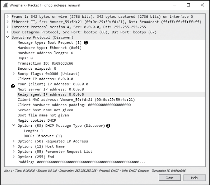
Figure 9-3: The DHCP discover packet
NOTE
Because Wireshark still references BOOTP when dealing with DHCP, you’ll see a Bootstrap Protocol section in the Packet Details pane, rather than a DHCP section. Nevertheless, I’ll refer to this as the packet’s DHCP portion throughout this book.
This packet is a request, identified by the (1) in the Message type field ➊. Most of the fields in this discovery packet are either all zeros (as you can see in the IP address fields ➋) or pretty self-explanatory, based on the listing of DHCP fields in the previous section. The meat of this packet is in its four Option fields ➌.
DHCP Message Type This is option type 53, with length 1 and a value of Discover (1). These values indicate that this is a DHCP discover packet.
Client Identifier This provides additional information about the client requesting an IP address.
Requested IP Address This supplies the IP address the client would like to receive. This can be a previously used IP address or 0.0.0.0 to indicate no preference.
Parameter Request List This lists the different configuration items (IP addresses of other important network devices and other non IP items) the client would like to receive from the DHCP server.
The Offer Packet
The second packet in this file lists valid IP addresses in its IP header, showing a packet traveling from 192.168.1.5 to 192.168.1.10, as shown in Figure 9-4. The client doesn’t actually have the 192.168.1.10 address yet, so the server will first attempt to communicate with the client using its hardware address, as provided by ARP. If communication isn’t possible, the server will simply broadcast the offer to communicate.
The DHCP portion of this second packet, called the offer packet, indicates that the Message type is a reply ➊. This packet contains the same Transaction ID as the previous packet ➋, which tells us that this reply is indeed a response to our original request.
The offer packet is sent by the DHCP server in order to offer its services to the client. It does so by supplying information about itself and the addressing it wants to provide the client. In Figure 9-4, the IP address 192.168.1.10 in the Your (client) IP address field is being offered to the client ➌ from 192.168.1.5 identified by the Next server IP address field ➍.
The first option listed identifies the packet as a DHCP Offer ➎. The options that follow are supplied by the server and indicate the additional information it can offer, along with the client’s IP address. You can see that it offers the following:
• An IP address lease time of 10 minutes
• A subnet mask of 255.255.255.0
• A broadcast address of 192.168.1.255
• A router address of 192.168.1.254
• A domain name of mydomain.example
• Domain name server addresses of 192.168.1.1 and 192.168.1.2
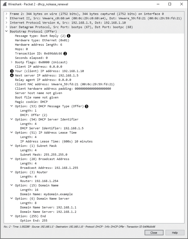
Figure 9-4: The DHCP offer packet
The Request Packet
Once the client receives an offer from the DHCP server, it should accept it with a DHCP request packet, as shown in Figure 9-5.
The third packet in this capture still comes from IP address 0.0.0.0, because we have not yet completed the process of obtaining an IP address ➊. The packet now knows the DHCP server it is communicating with.

Figure 9-5: The DHCP request packet
The Message type field shows that this packet is a request ➋, and the Transaction ID field is the same as in the first two packets ➌, indicating they are part of the same process. This packet is similar to the discover packet, in that all of its IP-addressing information is zeroed.
Finally, in the Option fields, we see that this is a DHCP Request ➍. Notice that the requested IP address is no longer blank and that the DHCP Server Identifier field also contains an address ➎.
The Acknowledgment Packet
In the final step in this process, the DHCP server sends the requested IP addresses to the client in an acknowledgment packet and records that information in its database, as shown in Figure 9-6. The client now has an IP address and can use it to begin communicating on the network.
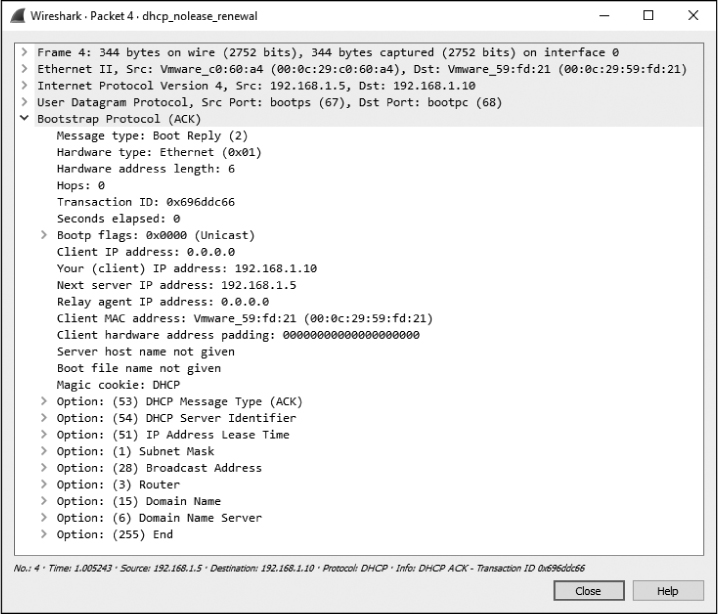
Figure 9-6: The DCHP acknowledgment packet
DHCP In-Lease Renewal
dhcp_inlease _renewal.pcapng
When a DHCP server assigns an IP address to a device, it leases it to the client. This means that the client is allowed to use the IP address for only a limited amount of time before it must renew the lease. The DORA process just discussed occurs the first time a client gets an IP address or when its lease time has expired. In either case, the device is considered to be out of lease.
When a client with an IP address in-lease reboots, it must perform a truncated version of the DORA process in order to reclaim its IP address. This process is called an in-lease renewal.
In the case of a lease renewal, the discovery and offer packets are unnecessary. Think of an in-lease renewal as being the same DORA process used in an out-of-lease renewal, but the in-lease renewal doesn’t need to do as much, leaving only the request and acknowledgment steps. You’ll find a sample capture of an in-lease renewal in the file dhcp_inlease_renewal.pcapng.
DHCP Options and Message Types
DHCP’s real flexibility lies in its available options. As you’ve seen, the packet’s DHCP options can vary in size and content. The packet’s overall size depends on the combination of options used. You can view a full list of the many DHCP options at http://www.iana.org/assignments/bootp-dhcp-parameters/.
The only option required in all DHCP packets is the Message type option (option 53). This option identifies how the DHCP client or server will process the information contained within the packet. There are 8 message types, as defined in Table 9-1.
Type number |
Message type |
Description |
1 |
Discover |
Used by the client to locate available DHCP servers |
2 |
Offer |
Sent by the server to the client in response to a discover packet |
3 |
Request |
Sent by the client to request the offered parameters from the server |
4 |
Decline |
Sent by the client to the server to indicate invalid parameters within a packet |
5 |
ACK |
Sent by the server to the client with the configuration parameters requested |
6 |
NAK |
Sent by the client to the server to refuse a request for configuration parameters |
7 |
Release |
Sent by the client to the server to cancel a lease by releasing its configuration parameters |
8 |
Inform |
Sent by the client to the server to ask for configuration parameters when the client already has an IP address |
DHCP Version 6 (DHCPv6)
dhcp6_outlease_acquisition.pcapng
If you examine the packet structure for a DHCP packet in Figure 9-1, you’ll see that it doesn’t provide enough room to support the length required for IPv6 address allocation. Instead of retrofitting DHCP for this purpose, DHCPv6 was devised in RFC3315. Since DHCPv6 isn’t built on the concept of BOOTP, its packet format is much simpler (Figure 9-7).
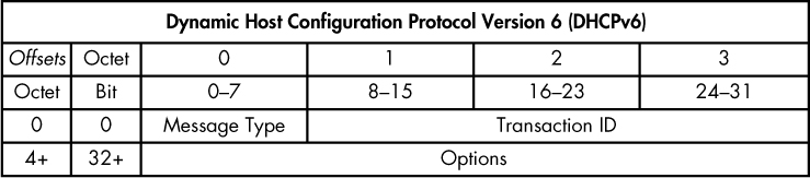
Figure 9-7: The DHCPv6 packet structure
The packet structure shown here contains only two static values, which function in the same manner as their DHCP counterparts. The rest of the packet structure varies depending on the message type identified in the first byte. Within the Options section, each option is identified with a 2-byte option code and a 2-byte length field. A full list of message types and option codes that can appear in these fields can be found here: http://www.iana.org/assignments/dhcpv6-parameters/dhcpv6-parameters.xhtml.
DHCPv6 accomplishes the same goal as DHCP, but to understand the flow of DHCPv6 communication, we must replace our DORA acronym with a new one, SARR. This process is illustrated in Figure 9-8, which represents a client that is currently out of lease.
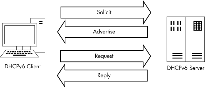
Figure 9-8: The DHCPv6 SARR out-of-lease renewal process
The SARR process has four steps:
Solicit: An initial packet is sent from a client to a special multicast address (ff02::1:2) to attempt to locate available DHCPv6 servers on the network.
Advertise: An available server responds directly to the client to indicate that it is available to provide addressing and configuration information.
Request: The client sends a formal request for configuration information to the server via multicast.
Reply: The server sends all available requested configuration information directly to the client, and the process is complete.
A summary of this process is shown in Figure 9-9, which is taken from the file dhcp6_outlease_acquisition.pcapng. In this example, we see the SARR process in action as a new host on the network (fe80::20c:29ff:fe5e:7744) receives configuration information from a DHCPv6 server (fe80::20c:29ff :fe1f:a755). Each packet represents one step of the SARR process, with the initial solicit and advertise packets tied together using the transaction ID 0x9de03f and the request and reply packets associated with the transaction ID 0x2d1603. While it isn’t shown in the figure, this communication takes place over ports 546 and 547, which are the standard ports used by DHCPv6.

Figure 9-9: A client obtaining an IPv6 address via DHCPv6
Overall, the packet structure of DHCPv6 traffic looks a lot different, but most of the same concepts apply. The process still requires some form of DHCP server discovery and a formal retrieval of configuration information. Those transactions are all tied together via transaction identifiers in each pair of packets exchanged between the client and server. IPv6 addressing can’t be supported by traditional DHCP mechanisms, so if you have devices getting IPv6 addresses automatically from a server on your network, it’s likely that you’re already running DHCPv6 services on your network. If you’d like to compare DHCP and DHCPv6 further, I recommend opening the packet captures discussed in this chapter side by side and stepping through them.
Domain Name System (DNS)
The Domain Name System (DNS) is one of the most crucial internet protocols because it is the proverbial molasses that holds the bread together. DNS ties domain names, such as www.google.com, to IP addresses, such as 74.125.159.99. When we want to communicate with a networked device and we don’t know its IP address, we access that device via its DNS name.
DNS servers store a database of resource records of IP address–to–DNS name mappings, which they share with clients and other DNS servers.
NOTE
Because the architecture of DNS servers is complicated, we’ll just look at some common types of DNS traffic. You can review the various DNS-related RFCs at https://www.isc.org/community/rfcs/dns/.
DNS Packet Structure
As you can see in Figure 9-10, the DNS packet structure is somewhat different from that of the packet types we’ve discussed previously. The following fields can be present within a DNS packet:
DNS ID Number Used to associate DNS queries with DNS responses
Query/Response (QR) Denotes whether the packet is a DNS query or response
OpCode Defines the type of query contained in the message
Authoritative Answers (AA) If this value is set in a response packet, indicates that the response is from a name server with authority over the domain
Truncation (TC) Indicates that the response was truncated because it was too large to fit within the packet
Recursion Desired (RD) When this value is set in a query, indicates that the DNS client requests a recursive query if the target name server doesn’t contain the information requested
Recursion Available (RA) If this value is set in a response, indicates that the name server supports recursive queries

Figure 9-10: The DNS packet structure
Reserved (Z) Defined by RFC 1035 to be set as all zeros; however, sometimes it’s used as an extension of the RCode field
Response Code (RCode) Used in DNS responses to indicate the presence of any errors
Question Count The number of entries in the Questions Section
Answer Count The number of entries in the Answers Section
Name Server (Authority) Record Count The number of name server resource records in the Authority Section
Additional Records Count The number of other resource records in the Additional Information Section
Questions Section Variable-sized section that contains one or more queries for information to be sent to the DNS server
Answers Section Variable-sized section that carries one or more resource records that answer queries
Authority Section Variable-sized section that contains resource records that point to authoritative name servers that can be used to continue the resolution process
Additional Information Section Variable-sized section that contains resource records that hold additional information related to the query that is not absolutely necessary to answer the query
A Simple DNS Query
dns_query_response.pcapng
DNS functions in a query-response format. A client wishing to resolve a DNS name to an IP address sends a query to a DNS server, and the server sends the requested information in its response. In its simplest form, this process takes two packets, as can be seen in the capture file dns_query_response.pcapng.
The first packet, shown in Figure 9-11, is a DNS query sent from the client 192.168.0.114 to the server 205.152.37.23 on port 53, which is the standard port used by DNS.
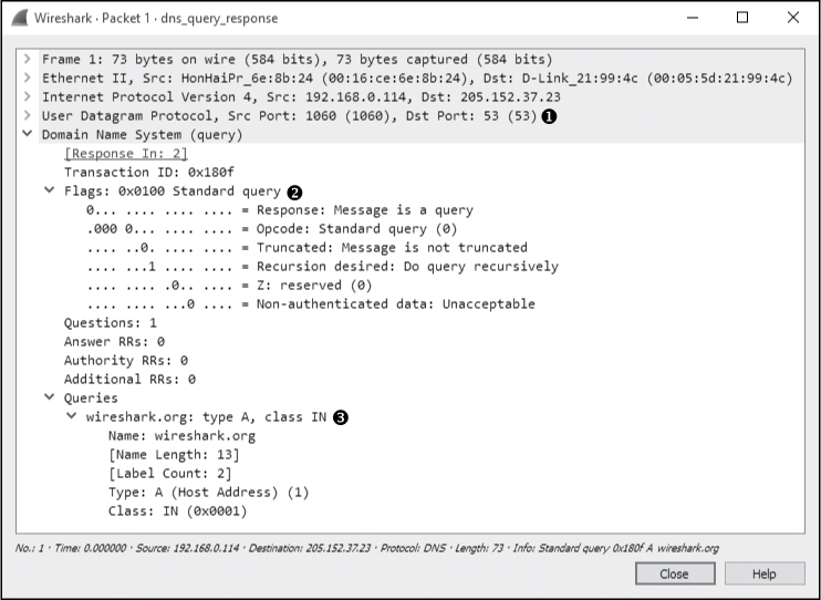
Figure 9-11: The DNS query packet
When you begin examining the headers in this packet, you’ll see that DNS also relies on UDP ➊.
In the DNS portion of the packet, you can see that smaller fields near the beginning of the packet are condensed by Wireshark into a single Flags section. Expand this section, and you’ll see that the message is indeed a standard query ➋, that it is not truncated, and that recursion is desired (we’ll cover recursion shortly). Only a single question is identified, which can be found by expanding the Queries section. There, you can see the query is for the name wireshark.org for a host (type A) internet (IN) address ➌. This packet is basically asking, “Which IP address is associated with the wireshark.org domain?”
The response to this request is in packet 2, as shown in Figure 9-12. Because this packet has an identical identification number ➊, we know that it contains the correct response to the original query.
The Flags section confirms that this is a response and that recursion is available if necessary ➋. This packet contains only one question and one resource record ➌, because it includes the original question in conjunction with its answer. Expanding the Answers section gives us the response to the query: the IP address of wireshark.org is 128.121.50.122 ➍. With this information, the client can now construct IP packets and begin communicating with wireshark.org.
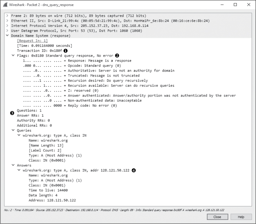
Figure 9-12: The DNS response packet
DNS Question Types
The Type fields used in DNS queries and responses indicate the resource record type that the query or response is for. Some of the more common message/resource record types are listed in Table 9-2. You’ll be seeing these types throughout normal traffic and in this book. (The list in Table 9-2 is brief and by no means exhaustive. To review all DNS resource record types, visit http://www.iana.org/assignments/dns-parameters/.)
Table 9-2: Common DNS Resource Record Types
Value |
Type |
Description |
1 |
A |
IPv4 host address |
2 |
NS |
Authoritative name server |
5 |
CNAME |
Canonical name for an alias |
15 |
MX |
Mail exchange |
16 |
TXT |
Text string |
28 |
AAAA |
IPv6 host address |
251 |
IXFR |
Incremental zone transfer |
252 |
AXFR |
Full zone transfer |
DNS Recursion
dns_recursivequery_client.pcapng, dns_recursivequery_server.pcapng
Due to the hierarchical nature of the internet’s DNS structure, DNS servers must be able to communicate with each other in order to answer the queries submitted by clients. While we expect our internal DNS server to know the name-to-IP address mapping of our local intranet server, we can’t expect it to know the IP address associated with Google or Dell.
When a DNS server needs to find an IP address, it queries another DNS server on behalf of the client making the request, in effect acting like a client. This process is called recursion.
To view the recursion process from both the DNS client and server perspectives, open the file dns_recursivequery_client.pcapng. This file contains a capture of a client’s DNS traffic file in two packets. The first packet is the initial query sent from the DNS client 172.16.0.8 to its DNS server 172.16.0.102, as shown in Figure 9-13.

Figure 9-13: The DNS query with the Recursion desired bit set
When you expand the DNS portion of this packet, you’ll see that this is a standard query for an A type record for the DNS name www.nostarch.com ➋. To learn more about this packet, expand the Flags section, and you’ll see that recursion is desired ➊.
The second packet is what we would expect to see in response to the initial query, as shown in Figure 9-14.
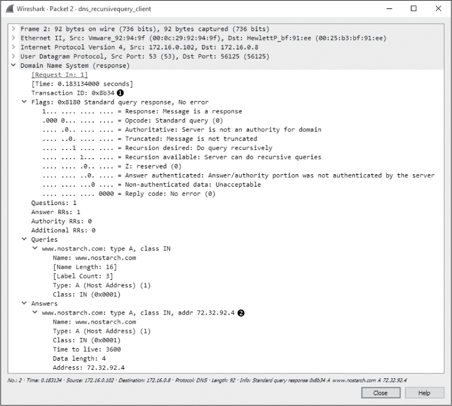
Figure 9-14: The DNS query response
This packet’s transaction ID matches that of our query ➊, no errors are listed, and we receive the A type resource record associated with www.nostarch.com ➋.
We can see that this query was answered by recursion by listening to the DNS server’s traffic when the recursion is taking place, as demonstrated in the file dns_recursivequery_server.pcapng. This file shows a capture of the traffic on the local DNS server when the query was initiated (Figure 9-15).
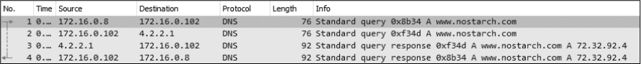
Figure 9-15: DNS recursion from the server’s perspective
The first packet is the same initial query we saw in the previous capture file. At this point, the DNS server has received the query, checked its local database, and realized it doesn’t know the answer to the question of which IP address goes with the DNS name (www.nostarch.com). Because the packet was sent with the Recursion desired bit set, the DNS server can ask another DNS server this question in an attempt to locate the answer, as you can see in the second packet.
In the second packet, the DNS server at 172.16.0.102 transmits a new query to 4.2.2.1 ➊, which is the server to which it is configured to forward upstream requests, as shown in Figure 9-16. This query mirrors the original one, effectively turning the DNS server into a client. We can tell that this is a new query because the transaction ID number differs from the transaction ID number in the previous capture file ➋.

Figure 9-16: The recursive DNS query
Once this packet is received by server 4.2.2.1, the local DNS server receives the response shown in Figure 9-17.

Figure 9-17: Response to the recursive DNS query
Having received this response, the local DNS server can transmit the fourth and final packet to the DNS client with the information requested.
Although this example shows only one layer of recursion, recursion can occur many times for a single DNS request. Here, we received an answer from the DNS server at 4.2.2.1, but that server could have retransmitted the query recursively to another server in order to find the answer. A simple query can travel all over the world before it finally gets a correct response. Figure 9-18 illustrates the recursive DNS query process.
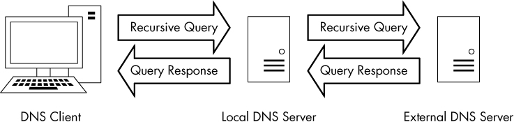
Figure 9-18: A recursive DNS query
DNS Zone Transfers
dns_axfr.pcapng
A DNS zone is the namespace (or group of DNS names) that a DNS server has been delegated to manage. For instance, Emma’s Diner might have one DNS server responsible for emmasdiner.com. In that case, devices both inside and outside Emma’s Diner wishing to resolve emmasdiner.com to an IP address would need to contact that DNS server as the authority for that zone. If Emma’s Diner were to grow, it could add a second DNS server to handle the email portion of its DNS namespace only, say mail.emmasdiner.com, and that server would be the authority for that mail subdomain. Additional DNS servers might be added for subdomains as necessary, as shown in Figure 9-19.
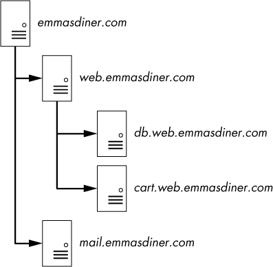
Figure 9-19: DNS zones divide responsibility for namespaces.
A zone transfer occurs when zone data is transferred between two devices, typically out of desire for redundancy. For example, in organizations with multiple DNS servers, administrators commonly configure a secondary DNS server to maintain a copy of the primary server’s DNS zone information in case the primary server becomes unavailable. There are two types of zone transfers:
Full zone transfer (AXFR) These types of transfers send an entire zone between devices.
Incremental zone transfer (IXFR) These types of transfers send only a portion of the zone information.
The file dns_axfr.pcapng contains an example of a full zone transfer between the hosts 172.16.16.164 and 172.16.16.139. When you first look at this file, you may wonder whether you’ve opened the right one, because rather than UDP packets, you see TCP packets. Although DNS relies on UDP, it uses TCP for certain tasks, such as zone transfers, because TCP is more reliable for the amount of data being transferred. The first three packets in this capture file are the TCP three-way handshake.
The fourth packet begins the zone transfer request between 172.16.16.164 and 172.16.16.139. This packet doesn’t contain any DNS information. It’s marked as a “TCP segment of a reassembled PDU” because the data sent in the zone transfer request packet was sent in multiple packets. Packets 4 and 6 contain the packet’s data. Packet 5 is the acknowledgment that packet 4 was received. These packets are displayed in this manner because of the way Wireshark parses and displays TCP packets for easier readability. For our purposes, we can reference packet 6 as the complete DNS zone transfer request, as shown in Figure 9-20.
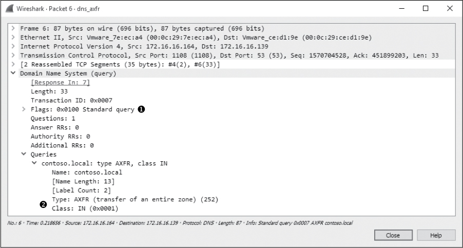
Figure 9-20: DNS full zone transfer request
The zone transfer request is a standard query ➊, but instead of requesting a single record type, it requests the AXFR type ➋, meaning that it wishes to receive the entire DNS zone from the server. The server responds with the zone records in packet 7, as shown in Figure 9-21. As you can see, the zone transfer contains quite a bit of data, and this is one of the simpler examples! With the zone transfer complete, the capture file ends with the TCP connection teardown process.
WARNING
The data contained in a zone transfer can be very dangerous in the wrong hands. For example, by enumerating a single DNS server, you can map a network’s entire infrastructure.
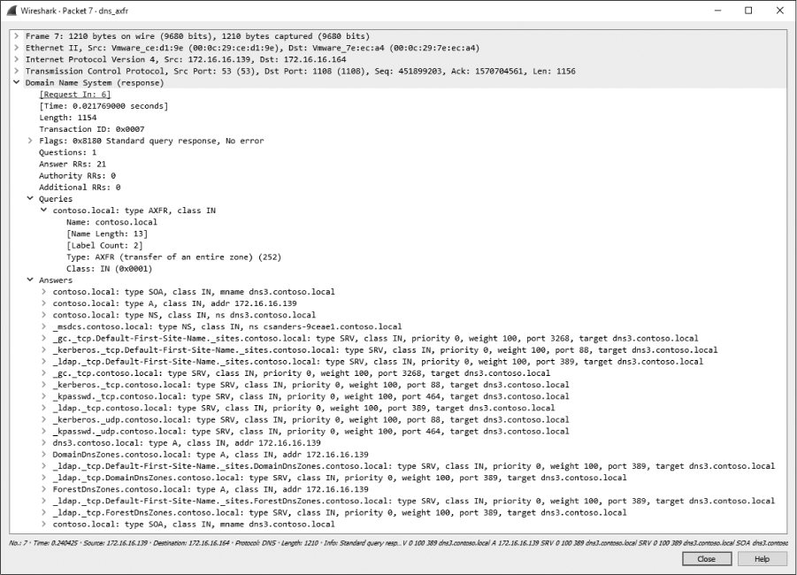
Figure 9-21: The DNS full zone transfer occurring
Hypertext Transfer Protocol (HTTP)
The Hypertext Transfer Protocol is the delivery mechanism of the World Wide Web, allowing web browsers to connect to web servers to view web pages. In most organizations, HTTP represents, by far, the highest percentage of traffic seen going across the wire. Every time you do a Google search, send a tweet, or check University of Kentucky basketball scores on http://www.espn.com/, you’re using HTTP.
We won’t look at the packet structures for an HTTP transfer because there are so many different implementations of the HTTP protocol that the structure may vary wildly. Because of this variance, that exercise is left to you. Here, we’ll look at some practical applications of HTTP such as retrieving and posting content.
Browsing with HTTP
http_google.pcapng
HTTP is most commonly used to browse web pages on a web server using a browser. The capture file http_google.pcapng shows such an HTTP transfer, using TCP as the transport layer protocol. Communication begins with a three-way handshake between the client 172.16.16.128 and the Google web server 74.125.95.104.
Once communication is established, the first packet is marked as an HTTP packet from the client to the server, as shown in Figure 9-22.
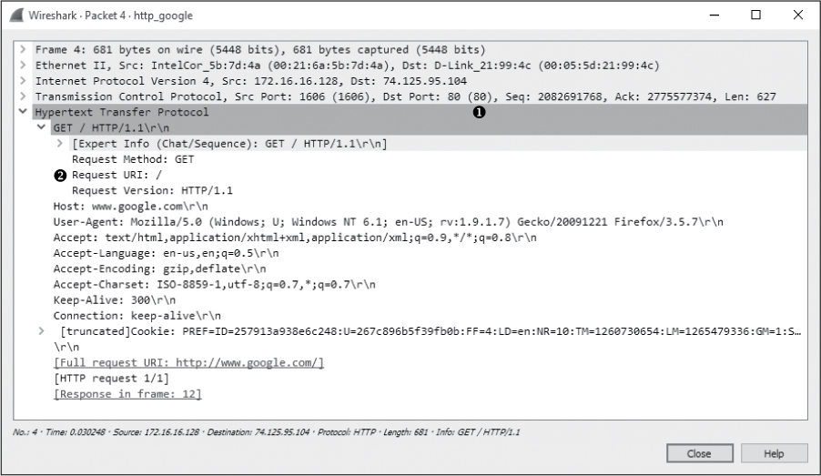
Figure 9-22: The initial HTTP GET request packet
The HTTP packet is delivered over TCP to the server’s port 80 ➊, the standard port for HTTP communication (several other ports are often used as well, such as 8080 and 8888).
HTTP packets are identified by one of eight request methods as defined in HTTP specification version 1.1 (see http://www.iana.org/assignments/http-methods/http-methods.xhtml), which indicate the action the packet’s transmitter will perform on the receiver. As shown in Figure 9-22, this packet identifies its method as GET, its request Uniform Resource Indicator (URI) as /, and the request version as HTTP/1.1 ➋. This information tells us that the client is sending a request to download (GET) the root web directory (/) of the web server using version 1.1 of HTTP.
Next, the host sends information about itself to the web server. This information includes things such as the browser (User-Agent) being used, languages accepted by the browser (Accept-Languages), and cookie information (at the bottom of the capture). The server can use this information to determine which data to return to the client in order to ensure compatibility.
When the server receives the HTTP GET request in packet 4, it responds with a TCP ACK, acknowledging the packet, and begins transmitting the requested data from packets 6 to 11. HTTP is used only to issue application-layer commands between the client and server. Why do all these HTTP packets show up as TCP under the protocol heading in the packet list? When data transfer begins, the Wireshark packet list window will identify those packets as TCP instead of HTTP since no HTTP request/response headers are present in those individual packets. Thus, where data transfer is occurring, you see TCP instead of HTTP in the Protocol column. Nonetheless, this is still part of the HTTP communication process.
Data is sent from the server in packets 6 and 7, an acknowledgment from the client in packet 8, two more data packets in packets 9 and 10, and another acknowledgment in packet 11, as shown in Figure 9-23. All of these packets are shown in Wireshark as TCP segments, rather than as HTTP packets, although HTTP is still responsible for their transmission.
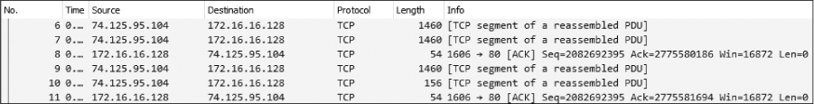
Figure 9-23: TCP transmitting data between the client browser and web server
Once the data is transferred, Wireshark reassembles the data stream for viewing, as shown in Figure 9-24.

Figure 9-24: Final HTTP packet with response code 200
NOTE
In many instances, you won’t be able to see readable HTML data when browsing through the packet list because that data is gzip compressed to increase bandwidth efficiency. This is signified by the Content-Encoding field in the HTTP response from the web server. It’s only when you view the full stream that the data is decoded and easily readable.
HTTP uses a number of predefined response codes to indicate the results of a request method. In this example, we see a packet with status code 200 ➊, which indicates a successful request method. The packet also includes a timestamp and some additional information about the encoding of the content and configuration parameters of the web server. When the client receives this packet, the transaction is complete.
Posting Data with HTTP
http_post.pcapng
Now that we have looked at the process of downloading data from a web server, let’s turn our attention to uploading data. The file http_post.pcapng contains a very simple example of an upload: a user posting a comment to a web-site. After the initial three-way handshake, the client (172.16.16.128) sends an HTTP packet to the web server (69.163.176.56), as shown in Figure 9-25.
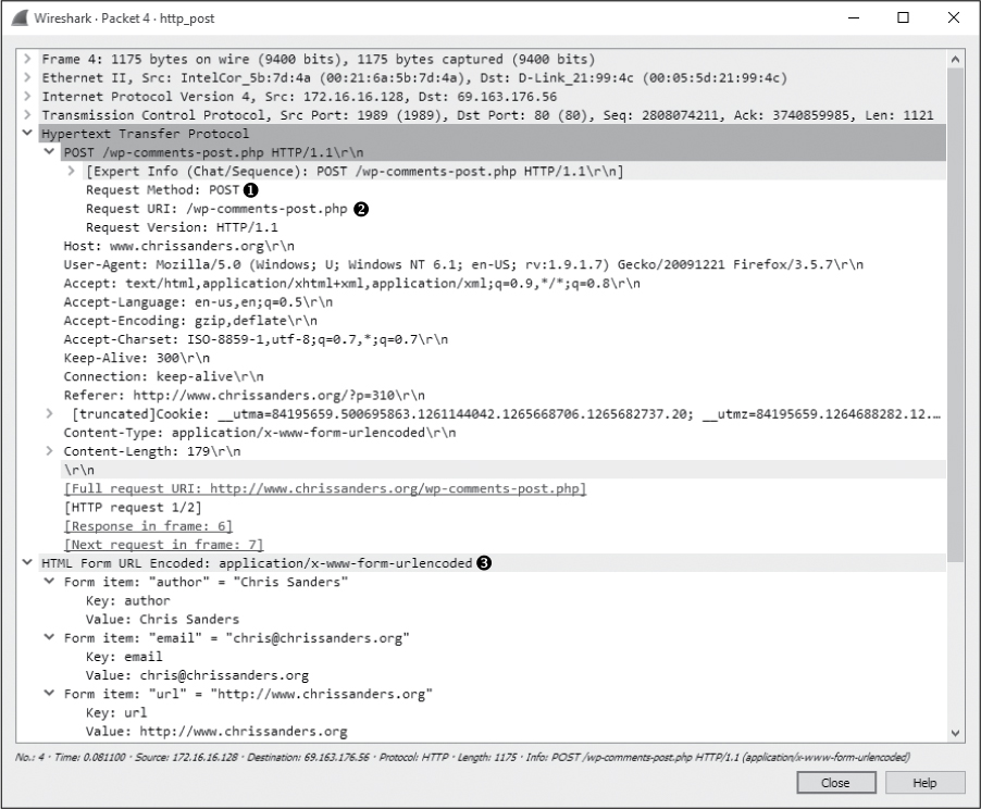
Figure 9-25: The HTTP POST packet
This packet uses the POST method ➊ to upload data to a web server for processing. The POST method used here specifies the URI /wp-comments-post.php ➋ and the HTTP version of HTTP/1.1. To see the contents of the data posted, expand the HTML Form URL Encoded portion of the packet ➌.
Once the data is transmitted in this POST, an ACK packet is sent. As shown in Figure 9-26, the server responds with packet 6, transmitting the response code 302 ➊, which means “found.”
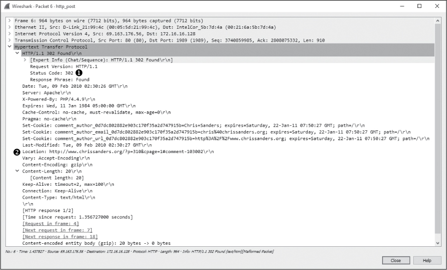
Figure 9-26: HTTP response 302 is used to redirect.
The 302 response code is a common means of redirection in the HTTP world. The Location field in this packet specifies where the client is to be directed ➋. In this case, that location is on the originating web page where the comment was posted. The client performs a new GET request to retrieve content at the new location, which it sends over the next several packets. Finally, the server transmits status code 200, and the communication ends.
Simple Mail Transfer Protocol (SMTP)
If web browsing is the most common activity a user will participate in, sending and receiving email is probably in second place. The Simple Mail Transfer Protocol (SMTP), used by platforms such as Microsoft Exchange and Postfix, is the standard for sending email.
As with HTTP, the structure of an SMTP packet can vary based on the implementation and the set of features supported by the client and server. In this section, we’ll review some of the basic functionality of SMTP by examining what sending email looks like at the packet level.
Sending and Receiving Email
The architecture supporting email is similar to the US Postal Service. When you write a letter, you put it in your mailbox, a postal worker picks it up, and it’s transported to a post office where it’s sorted. From there, the letter is either delivered to another mailbox serviced by that same post office or transported to another post office that is responsible for delivering it. A letter may traverse multiple post offices or even “hub” offices designed exclusively to distribute to post offices in specific geographic regions. This flow of information is illustrated in Figure 9-27.
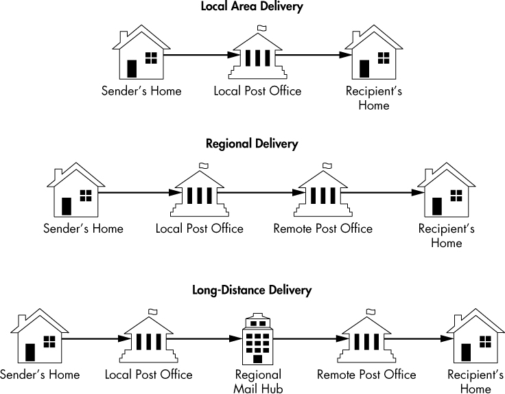
Figure 9-27: Sending a letter via the postal service
Delivering email works in a very similar manner, but the terminology is a bit different. At the individual user level, the physical mailbox is replaced by a digital mailbox that is responsible for storing and facilitating the sending and receiving of your email. You access this mailbox with a mail user agent (MUA), which is an email client like Microsoft Outlook or Mozilla Thunderbird.
When you send a message, it’s sent from your MUA to a mail transfer agent (MTA). The MTA is often referred to as the mail server, with popular mail server applications being Microsoft Exchange or Postfix. If the email being sent is destined for the same domain it came from, the MTA can associate it with the recipient mailbox without any further communication. If the email is being sent to another domain, the MTA must use DNS to find the location address of the recipient mail server, then transmit the message to it. It’s worth noting that the mail server is often made up of other components like a Mail Delivery Agent (MDA) or a Mail Submission Agent (MSA), but from the network standpoint, we’ll usually only be interested in the concept of a client and a server. This basic overview is illustrated in Figure 9-28.

Figure 9-28: Sending an email via SMTP
For simplicity’s sake, we’ll refer to the MUA as the email client and the MTA as the email server.
Tracking an Email Message
With a basic understanding of how email messages are transmitted, we can begin to look at packets that represent this process. Let’s start with the scenario outlined in Figure 9-29.
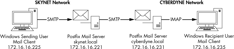
Figure 9-29: Tracking an email from sender to recipient
There are three steps in this scenario:
A user sends a message from their workstation (172.16.16.225). The email client transmits the message via SMTP to the local email server (172.16.16.221 / skynet.local domain).
The local email server receives the message and transmits it to a remote email server (172.16.16.231 / cyberdyne.local domain) via SMTP.
The remote email server receives the message and associates it with the appropriate mailbox. The email client on a user’s workstation (172.16.16.235) retrieves this message using the IMAP protocol.
Step 1: Client to Local Server
mail_sender_client_1.pcapng
We’ll begin stepping through this process by reviewing step 1, which is represented by mail_sender_client_1.pcapng. The file begins when the user clicks the Send button in their email client, initiating the TCP handshake between their workstation and the local email server in packets 1 through 3.
NOTE
You can ignore any ETHERNET FRAME CHECK SEQUENCE INCORRECT errors observed while analyzing the packet captures in this section. They are an artifact of the lab environment in which these were created.
Once a connection is established, SMTP takes over and begins the work of transmitting the user’s message to the server. You could examine each SMTP request and response individually by scrolling through each packet and viewing the SMTP section of the Packet Details window, but there is an easier way. Since SMTP is a simple transactional protocol and our example is in clear text, you can follow the TCP stream to view the entire transaction in one window. Do this by right-clicking any packet in the capture and selecting Follow ▶ TCP Stream. The resulting stream is shown in Figure 9-30.
With a connection established, the email server sends a service banner to the client in packet 4 to indicate that it is ready to receive a command. In this case, it identifies itself as a Postfix server running on the Ubuntu Linux operating system ➊. It also identifies that it is capable of receiving Extended SMTP (ESMTP) commands. ESMTP is an extension to the SMTP specification that allows for additional commands to be used during mail transmission.
The email client responds by issuing the EHLO command in packet 5 ➋. EHLO is the “Hello” command used to identify the sending host when ESMTP is supported. If ESMTP is not available, the client will revert to the HELO command to identify itself. In this example, the sender is identified by its IP address, although a DNS name can be used as well.
In packet 7, the server responds with a list of items that include things like VRFY, STARTTLS, and SIZE 10240000 ➌. This list, which reflects commands supported by the SMTP server, is provided so that the client knows what commands it is allowed to use when transmitting the message. This feature negotiation occurs at the beginning of every SMTP transaction before a message is sent. The transmission of the message begins at packet 8 and makes up most of the remainder of this capture.

Figure 9-30: Viewing the TCP stream from the email client to the local server
SMTP is governed by simple commands and parameter values sent from the client, followed by a response code from the server. This is very similar to protocols like HTTP and TELNET and is designed for simplicity. An example request and reply can be seen in packets 8 and 9, where the client issues the MAIL command with the parameter FROM:<[email protected]> SIZE=556 ➍, and the server responds with response code 250 (Requested mail action okay, completed) and the 2.1.0 Ok parameter. Here, the client identifies the sender’s email address and the size of the message, and the server responds saying that this data was received and is acceptable. A similar transaction happens again in packets 10 and 11, where the client issues the RCPT command with the parameter TO:<[email protected]> ➎, and the server responds with another 250 2.1.5 Ok code.
NOTE
If you’d like to review all the available SMTP commands and parameters, you can do so here: http://www.iana.org/assignments/mail-parameters/mail-parameters.xhtml. If you’d like to review the available response codes, that can be done here: https://www.iana.org/assignments/smtp-enhanced-status-codes/smtp-enhanced-status-codes.xml.
All that is left is to transmit the message itself. The client initiates this process in packet 12 by issuing the DATA command. The server responds with code 354 along with a message ➏, which indicates that the server has created a buffer for the message and tells the client to begin transmitting. The line containing the code 354 tells the client to send a dot (<CR><LF>.<CR><LF>) to mark the end of the transmission. The message is transmitted in plaintext, and a response code indicating successful transmission is sent. You’ll notice the inclusion of some additional information with the message text, including the date, the content type and encoding, and the user agent associated with the transmission. This tells you that the end user who sent this message was using Mozilla Thunderbird ➐.
With transmission complete, the SMTP connection is terminated by the email client by issuing the QUIT command with no parameters in packet 18. The server responds in packet 19 with the response code 221 (<domain> ser-vice closing transmission channel) and the 2.0.0 Bye parameter ➑. The TCP connection is torn down gracefully in packets 20–23.
Step 2: Local Server to Remote Server
mail_sender_server_2.pcapng
Next we’ll examine the same scenario from the perspective of the local email server responsible for the skynet.local domain; its address is 172.16.16.221. This capture can be found in the file mail_sender_server_2.pcapng, which was taken directly from the email server. As you might expect, the first 20 or so packets mirror the capture in step 1, because they are the same packets captured from another source.
If the sent message was destined for another mailbox in the skynet.local domain, we wouldn’t see any more SMTP traffic; instead, we would see the retrieval of the message from an email client with the POP3 or IMAP protocol. However, since this message is destined for the cyberdyne.local domain, the local SMTP server must transmit the message to the remote SMTP server responsible for that domain. This process begins in packet 22 with a TCP handshake between the local server 172.16.16.221 and the remote mail server 172.16.16.231.
NOTE
In a real-world scenario, an email server locates another server by using a special DNS record type known as a mail exchange (MX) record. Since this scenario was created in a lab and the IP address of the remote email server was preconfigured on the local server, we won’t see that traffic here. If you’re troubleshooting email delivery, you should consider the potential for DNS issues along with email-specific protocol issues.
With a connection established, we can see in the Packet List window that SMTP is used to deliver the message to the remote server. You can better view this conversation by following the TCP stream for the transaction. It is shown in Figure 9-31. If you need help isolating this connection, apply the filter tcp.stream == 1 in the filter bar.
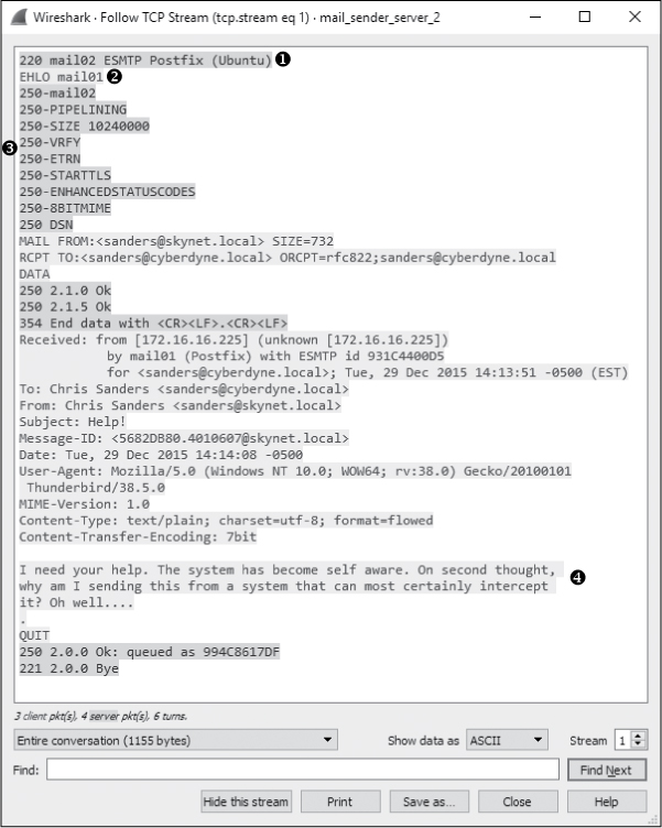
Figure 9-31: Viewing the TCP stream from the local email server to the remote email server
This transaction is nearly identical to the one in Figure 9-30. Essentially, the message is just being transmitted between servers. The remote server identifies itself as mail02 ➊, the local server identifies itself as mail01 ➋, a list of support commands is shared ➌, and the message is transferred in its entirety with a bit of additional data from the previous transaction prepended to the message above the To line ➍. This all occurs between packets 27 and 35, with a TCP teardown closing the communication channel.
The server ultimately doesn’t care whether the message is coming from an email client or another SMTP server, so all the same rules and procedures apply (barring any type of access control restrictions). In the real world, a local email server and a remote email server might not support the same feature set or might be based on entirely different platforms. This is why the initial SMTP communication is so important; it allows the recipient server to transmit its supported feature set to the sender. When an SMTP client or server is aware of the supported features of the recipient server, the SMTP commands can be adjusted so that the message can be transmitted effectively. This capability allows SMTP to be widely usable between any number of client and server technologies, and this is why you don’t have to know much about the network infrastructure of the recipient when sending an email.
Step 3: Remote Server to Remote Client
mail_receiver_server_3.pcapng
At this point, our message has reached the remote server responsible for delivering emails to mailboxes in the cyberdyne.local domain. We’ll now look at a packet capture taken from the perspective of the remote server, mail_ receiver_server_3.pcapng, shown in Figure 9-32.
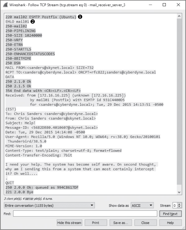
Figure 9-32: Viewing the TCP stream from the local email server to the remote email server
Once again, the first 15 packets in this capture look very familiar, as they are a representation of the same message being exchanged, with the source address representing the local email server ➊ and the destination address representing the remote email server ➋. Once this sequence is completed, the SMTP server can associate the message with the appropriate mailbox so that the intended recipient can retrieve it via their email client.
As mentioned earlier, SMTP is primarily used for sending email and is by far the most common protocol for that purpose. Retrieving email from a mailbox on a server is a bit more open-ended, and because of different needs arising in that space, there are several protocols that are designed to support this task. The most prevalent are Post Office Protocol version 3 (POP3) and Internet Message Access Protocol (IMAP). In our example, the remote client retrieves messages from the email server using IMAP in packets 16–34.
We don’t cover IMAP in this book, but in this example, it wouldn’t do you a ton of good even if we did because the communication is encrypted. If you look at packet 21, you’ll see the client (172.16.16.235) send the STARTTLS command to the email server (172.16.16.231) in packet 21 ➊, shown in Figure 9-33.
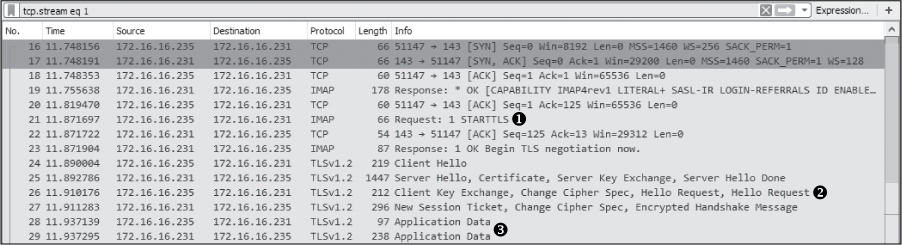
Figure 9-33: The STARTTLS command indicates that the IMAP traffic will be encrypted.
This command informs the server that the client would like to retrieve messages securely using TLS encryption. A secure channel is negotiated between each endpoint in packets 24–27 ➋, and the message is retrieved securely via the TLS (Transport Layer Security) protocol in the remaining packets ➌. If you click any of these packets to view the data or attempt to follow the TCP stream (Figure 9-34), you’ll find that the contents are unreadable, protecting the email from being intercepted by someone who might be attempting to hijack or sniff traffic maliciously.
With those final packets received, the process of sending a message from a user in one domain to a user in another domain is completed.
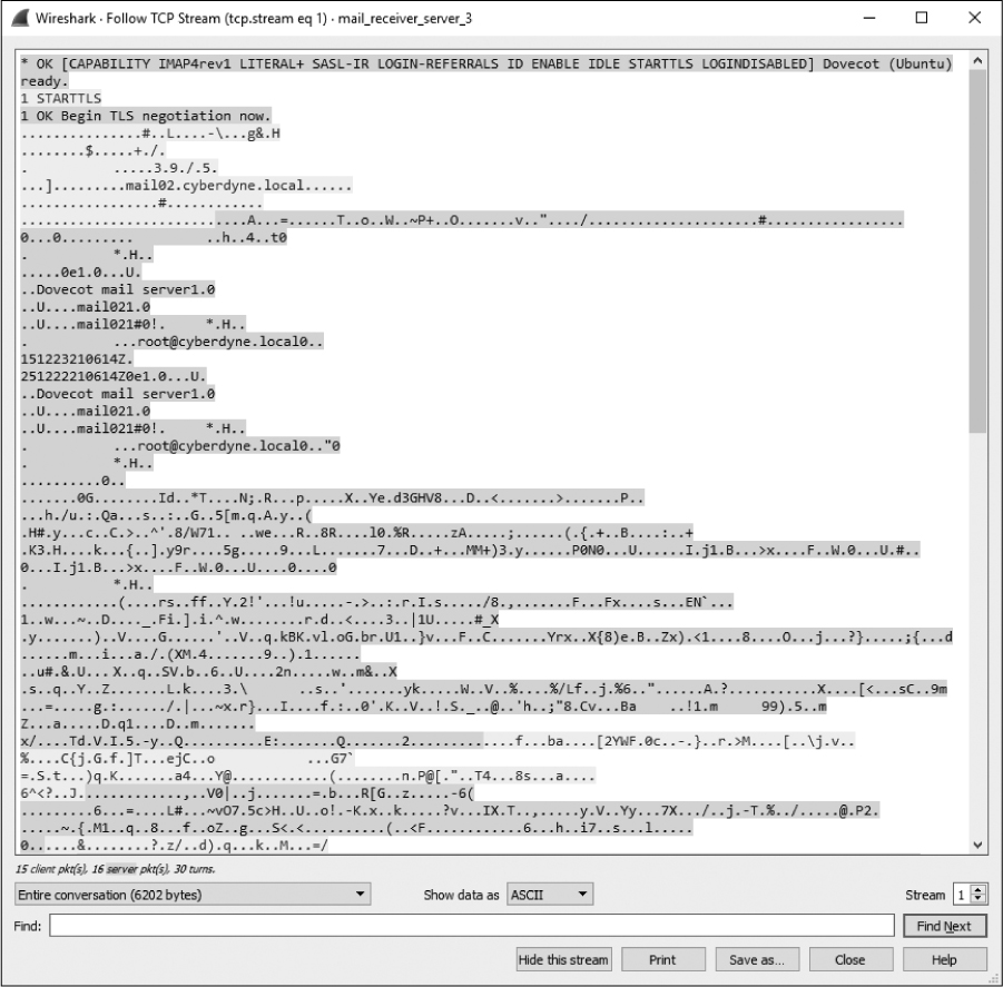
Figure 9-34: The IMAP traffic is encrypted as the client downloads the message.
Sending Attachments via SMTP
mail_sender _attachment.pcapng
SMTP was never intended to be a mechanism for transmitting files, but the ease of emailing a file means that it has become the primary sharing mechanism for many. Let’s walk through a quick example of what sending a file looks like at the packet level using SMTP.
In the packet capture mail_sender_attachment.pcapng, a user is sending an email message from their client (172.16.16.225) to another user on the same network via a local SMTP mail server (172.16.16.221). The message contains a bit of text and includes an image file attachment.
Sending an attachment via SMTP is not too different from sending text. It’s all just data to the server, and although some special encoding usually takes place, we still rely on the DATA command to get things where they’re going. To see this in action, open the capture file and follow the TCP stream for the given SMTP transaction. This stream is pictured in Figure 9-35.

Figure 9-35: A user sending an attachment via SMTP
This example begins like the previous scenarios with service identification and an exchange of supported protocols. When the client is ready to transmit the message, it does so by providing the From and To addresses, and sending the DATA command instructs the server to open up a buffer to receive the information. This is where things get a little different.
In the previous example, the client transmitted the text directly to the server, and that was it. In this example, the client must send the plaintext message, as well as the binary data associated with the image attachment. To make this happen, it identifies its Content-Type as multipart/mixed, with a boundary of ------------050407080301000500070000 ➊. This tells the server that multiple types of data are being transmitted, each with their own unique MIME type and encoding, and that each type of data will be separated with the boundary value specified. Therefore, when another mail client receives this data, it will know how to interpret the data based on the boundaries and the unique MIME type and encoding specified in each chunk.
In our example, we have two unique parts of this message. The first is the mail text itself, which is identified by the content type text/plain ➋. After that, we see a boundary marker and the start of a new part of the message ➌. This part contains the image file and is identified by the content type image/jpeg ➍. It’s also worth noting that the Content-Transfer-Encoding value is set to base64 ➎, meaning that the data must be converted from base 64 to be parsed. The remainder of the transmission includes the encoded image file ➏.
Whatever you do, don’t get this encoding confused with a security feature. Base 64 encoding is almost instantly reversible, and any attacker who intercepts this communication would be able to retrieve the image file without much effort. If you are interested in carving this image file out of the packet capture yourself, there is a similar scenario in which we carve an image from an HTTP-based file transfer in the Remote-Access Trojan section of Chapter 12. Once you’ve read that, flip back to this capture file and see if you can find out who the user’s mysterious new coworker is.
Final Thoughts
This chapter has introduced the most common protocols you will encounter when examining traffic at the application layer. In the following chapters, we’ll examine new protocols and additional features of the protocols we’ve covered here as we explore a wide range of real-world scenarios.
To learn more about individual protocols, read their associated RFCs or have a look at The TCP/IP Guide by Charles M. Kozierok (No Starch Press, 2005). Also, see the list of resources in Appendix A.