
8.4. Recycling Technologies and Processes: Case Study
8.4.1. Recycling Project of C&D Waste in Shangrao City
8.4.1.1. Pretreatment and Stacking Section

8.4.1.2. Crushing and Sorting Section of C&D Waste
8.4.1.3. Treatment Section of Heavy Metal–Contaminated C&D Waste
Surface Stripping
Crushing
Washing and Solid–liquid Separation
Eluting With Glyphosate and Solid–liquid Separation
Eluted C&D Waste

8.4.1.4. Classified Storage Section
8.4.1.5. Deep Processing and Combined Grinding Section
8.4.1.6. Manufacturing Section of Products

Table 8.23
General Layout and Land Coverage of This Project for Annual Treatment Scale of 300,000 t of Construction and Demolition Waste
| No. | Item | Land Coverage (m2) | Building Construction Area (m2) | Structure Construction Area (m2) |
| 1 | Stack area of demolition waste | 403 | 403 | |
| 2 | Pretreatment stack area | 4943 | 9886 | |
| 3 | Crushing, sorting, and classified storage workshop | 2889 | 5778 | |
| 4 | Deep processing workshop | 1099 | 2198 | |
| 5 | Metal pollutants disposing workshop | 550 | 1100 | |
| 6 | Storage warehouse of recycled micropowder | 320 | 900 | |
| 7 | Repair shop, warehouse | 763 | 763 | |
| 8 | Controlling center | 479 | 479 | |
| 9 | Test building | 1008 | 3024 | |
| 10 | Multifunctional building | 1008 | 3024 | |
| 11 | Product storage yard | 5000 | ||
| 12 | Guard room | 40 | 46 |

8.4.1.7. Labor Organization
8.4.2. Centralized Disposal and Recycling Project of C&D Waste in Nantong City
8.4.2.1. General Introduction of This Project and Its Processes
Table 8.24
Facilities in Pretreatment Section for Annual Treatment Scale of 300,000 t of Construction and Demolition Waste

Table 8.25
Facilities in Crushing and Sorting Section for Annual Treatment Scale of 300,000 t of Construction and Demolition Waste

Table 8.26
Facilities in Deep Processing Section for Annual Treatment Scale of 300,000 t of Construction and Demolition Waste

Table 8.27
Facilities in Product Manufacturing Section for Annual Treatment Scale of 300,000 t of Construction and Demolition Waste
| No. | Item | Model & Specification | QTY | |
| 1 | Ingredient storage bin 3 × 4 m3 (body fabric) | Aggregate storage bin | 4 m3 | 3 |
| Measuring bin | 1200 kg ± 2% | 1 | ||
| Sensor | CST-2000 | 4 | ||
| Cylinder | SC80 × 300-S-CB-Y | 3 | ||
| Vibrator | B-0.5 | 3 | ||
| Motor | 7.5 kW | 1 | ||
| Belt | B500 × 17.1 m | 1 | ||
| Frame | Steel structure | 1 | ||
| 2 | Blender (body fabric) | Blending barrel | JS750 | 1 |
| Motor reducer | 30 kW | 1 | ||
| Lifting motor | 7.5 kW | 1 | ||
| Lubrication system | 1 | |||
| Cylinder | SC160 × 300-S-TC-M-Y | 1 | ||
| 3 | Cement measuring system (body fabric) | Cement weighing hopper | 350 kg ± 1% | 1 |
| Sensor | CSB-250 | 3 | ||
| Butterfly valve | DN250 | 1 | ||
| Vibrator | B-0.25 | 1 | ||
| 4 | Water measuring system (body fabric) | Water measuring cylinder | 200 kg ± 1% | 1 |
| Transmission pump | 2.2 kW | 1 | ||
| Pipeline | 2″ | 1 | ||
| Sensor | CST-500 | 1 | ||
| Butterfly valve | DN80 | 1 | ||
| Filling valve | DN25 | 1 | ||
| 5 | Belt conveyor (body fabric) | Flat belt | B600 × 8 m (center distance) | 1 |
| Planet-cycloid retarder | 4 kW | 1 | ||
| Table Continued | ||||

| No. | Item | Model & Specification | QTY | |
| Frame | Steel structure | 1 | ||
| Tightener | 1 | |||
| Receiving hopper | 1 | |||
| 6 | Grading station 1 × 4 m3 (plus material) | Aggregate storage bin | 4 m3 | 1 |
| Measuring bin | 800 kg ± 2% | 1 | ||
| Sensor | CST-1000 | 4 | ||
| Cylinder | SC80 × 300-S-CB-Y | 1 | ||
| Vibrator | B-0.5 | 1 | ||
| Motor | 2.2 kW | 1 | ||
| Belt | B500 × 5 m | 1 | ||
| Frame | Steel structure | 1 | ||
| 7 | Vertical blender (plus material) | Blending barrel | JN350 | 1 |
| Motor reducer | 7.5 kW | 1 | ||
| Lifting motor | 4 kW | 1 | ||
| Cylinder | SC80 × 250-S-TC-Y | 1 | ||
| 8 | Cement measuring system (plus material) | Cement weighing hopper | 150 kg ± 1% | 1 |
| Sensor | CSB-250 | 3 | ||
| Butterfly valve | DN250 | 1 | ||
| Vibrator | B-0.25 | 1 | ||
| 9 | Water measuring system (plus material) | Water measuring cylinder | 80 kg ± 1% | 1 |
| Transmission pump | 1.1 kW | 1 | ||
| Pipeline | 1 1/4″ | 1 | ||
| Sensor | CST-250 | 1 | ||
| Butterfly valve | DN80 | 1 | ||
| Filling valve | DN25 | 1 | ||
| Table Continued | ||||

| No. | Item | Model & Specification | QTY | |
| 10 | Belt conveyor (plus material) | Flat belt | B500 × 7 m (center distance) | 1 |
| Planet-cycloid retarder | 2.2 kW | 1 | ||
| Frame | Steel structure | 1 | ||
| Tightener | 1 | |||
| Receiving hopper | 1 | |||
| 11 | Block molder | Host machine | QT10-15 | 1 |
| Vibrating motor (with frequency conversion, without independent fans) | 11 kW | 2 | ||
| Distributing motor | 4 kW | 1 | ||
| Pallet conveyor | 1 | |||
| Hydraulic system | 22 kW | 1 | ||
| Random mold | 1 | |||
| 12 | Plus material device | 1 | ||
| 13 | Heat insulating board conveying device | 1 | ||
| 14 | Wet product conveyor line | Sweeping motor | 0.18 kW | 1 |
| Frame | 1 | |||
| Spacing device | 1 | |||
| 15 | Elevator 10F | Frame | SBJ10 | 1 |
| Motor power | 7.5 kW | 1 | ||
| Lifting device | 1 | |||
| Table Continued | ||||

| No. | Item | Model & Specification | QTY | |
| 16 | Lowerator 10F | Frame | SBJ10 | 1 |
| Motor power | 7.5 kW | 1 | ||
| Lifting device | 1 | |||
| 17 | Composite vehicle | Conveyor (carrier) | 1 | |
| Actuating device for conveyor | 3 kW | 1 | ||
| Subequipped vehicle (10 floor) | 1 | |||
| Actuating device for subequipped vehicle | 3 kW | 1 | ||
| Speed control device | 1 | |||
| Positioning device | 1.5 kW | 1 | ||
| 18 | Dry product conveyor line | Frame | 1 | |
| Sweeping machine | 0.18 kW | 1 | ||
| Spacing device | 1 | |||
| 19 | Plate recycling line | Plate turnover machine | SF10 | 1 |
| Gear motor | 0.75 kW | 1 | ||
| Overpass | 1 | |||
| 20 | Stacking machine | Walking device | 1.1 kW | 1 |
| Clamp device | 1 | |||
| Lifting device | 1 | |||
| Rotation device | 0.55 kW | 1 | ||
| Prestack device | 1 | |||
| Hydraulic system | 15 kW | 1 | ||
| 21 | Pitch conveyor | Tank chain | 7.5 kW | 1 |
| 22 | Wood tray separator | Wood tray | 2.2 kW | 1 |
| Table Continued | ||||

| No. | Item | Model & Specification | QTY | |
| 23 | Processing line hydraulic system | Triphase asynchronism motor | Y180L-4 22 kW | 1 |
| 24 | Electronic controlling system | Electric cabinet | 3 | |
| Control console | 4 | |||
| Industrial computer | 19″ LED display | 2 | ||
| PLC | 4 | |||
| Touch screen | TP-177A (Siemens) | 3 | ||
| Transmission instrument | GM8802F | 6 | ||
| Connecting cable | 1 | |||
| 25 | Control room | 6000 × 2250 × 2500 | 1 | |
| 26 | Packaging system | Horizontal packing machine | 1 | |
| Packaging machine | 1 | |||
| Winding machine | 1 | |||
| Transporting line | 2.5 m | 4 | ||
| Packaging control console | 1 | |||
| 27 | Pneumatic system | Air compressor | 5.5 kW | 1 |
| Pipe | 1 | |||
| FR, FRL | 1 | |||
| 28 | Spiral conveyor | XL219 | φ219 × 6 m | 1 |
| XL165 | φ165 × 5.5 m | 1 | ||

Table 8.28
| Department | Number of Staff | |||||
| Day Shift | Morning Shift | Swing Shift | Night Shift | Non Shift | Total | |
| Construction & demolition waste pretreatment | 3 | 3 | 1 | 7 | ||
| Crushing and sorting | 4 | 4 | 1 | 9 | ||
| Deep grinding process | 3 | 3 | 1 | 7 | ||
| Storage and loading | 2 | 2 | ||||
| Product manufacturing | 5 | 5 | 1 | 11 | ||
| Mechanical maintenance | 2 | 2 | ||||
| Technical production (experiment) | 2 | 1 | 1 | 4 | ||
| Guard | 1 | 1 | 1 | 3 | ||
| Logistics, administration | 3 | 1 | 4 | |||
| Financing | 3 | 3 | ||||
| Management | 5 | 5 | ||||
| Total | 23 | 11 | 17 | 1 | 5 | 57 |

Table 8.29
Comparison of Handling Process and Recycled Products in Nantong City Project
| No. | Item | Plan 1 | Plan 2 | Plan 3 |
| 1 | Resource products | Concrete products, mortar, concrete aggregate and cementing materials | Concrete products, mortar | Road material (cushion) |
| 2 | Pretreatment | Multistage crushing, screening | Multistage crushing, screening | Single-stage crushing |
| 3 | Separation of bricks, gravel, concrete | Relatively complete | Relatively complete | Mixed |
| 4 | Usage of recycled aggregate | |||
| 4.1 | Stone | Various classes (5–25 mm), able to be produced into concrete products and aggregate | Various classes (5–25 mm), able to produce into concrete products and aggregate | Those particle size larger than 25 mm account for more than 60%, can only be produced into road construction materials |
| 4.2 | Grit | 0–5 mm, able to be produced into concrete products and premixed mortar | 0–5 mm, able to be produced into concrete products and premixed mortar | |
| 4.3 | Powder | ≤0.16 mm, specific surface area of about 3000 cm2/g, can be used as cementing (blending) material | ||
| 5 | Variety of recycled products | Diversified | Small | Single (very small) |
| 6 | Sales of recycled products | |||
| Table Continued | ||||

| No. | Item | Plan 1 | Plan 2 | Plan 3 |
| 6.1 | Annual treatment capacity of 300,000 t | Smooth, low market share | Risk existing, large amount which will hit the market | Risk existing |
| 6.2 | Annual treatment capacity of 500,000 t | Smooth, low market share | Large risk, cannot be accommodated in market | Large risk |
| 6.3 | Annual treatment capacity of 800,000–1,000,000 t | Small risk, diversified market | Huge risk | Huge risk |
| 7 | Environmental pollution | Little | Little | Much |
| 8 | Installed capacity | Very large | Large | Small |
| 9 | Land occupation | Large | Large | Small |
| 10 | Investment | Very large | Large | Small |
| 11 | Technical sophistication | Very high | High | Low |
| 12 | Reliability | High | High | High |
| 13 | Value of recycled products | Very high | High | Low |
| 14 | Sustainability | Good | Normal | Bad |

Table 8.30
Components of Projects and Their Functions and Construction Area for Annual Treatment Scale of 1,000,000 t of Construction and Demolition Waste in Nantong City Project
| No. | Section | Function | Construction Area (m2) |
| 1 | No. 1 combined workshop | Production of recycled powder and sand | 12,606 |
| 2 | Product manufacturing and steam curing workshop | Products manufacturing | 1730 |
| 3 | Comprehensive building | Office work | 2700 |
| 4 | Technical center | Research work | 2700 |
| 5 | Office | Dork business | 228 |
| 6 | Maintenance workshop | Maintenance of facilities | 48 |
| 7 | Entrance | Inspection | 48 |
| 8 | Canteen | Dinner | 1238 |
| 9 | No. 2 combined workshop | Manufacturing of recycled aggregates | 3230 |
| Total | 24,528 | ||

Table 8.31
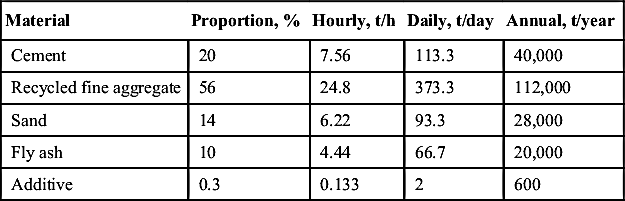
Material Balance of Annual Production of 100,000 m3 Recycled Concrete Products in Nantong City Project
| Material | Unit Consumption, t/m3 | Hourly Consumption, t | Daily Consumption, t | Annual Consumption, t |
| Cement | 0.30 | 6.67 | 100 | 30,000 |
| Sand | 0.15 | 3.33 | 50 | 15,000 |
| Recycled fine aggregate | 0.85 | 18.9 | 283.3 | 85,000 |
| Recycled coarse aggregate | 0.45 | 10 | 150 | 45,000 |
| Additive | 0.003 | 0.067 | 1 | 300 |
| Water | 0.18 | 4 | 60 | 18,000 |

8.4.2.2. Material Balance
Table 8.32
Material Balance of Annual Production of 100,000 m3 Recycled Concrete in Nantong City Project
| Material | Unit Consumption, t/m3 | Hourly Consumption, t | Daily Consumption, t | Annual Consumption, t |
| Cement | 0.28 | 11.2 | 112 | 28,000 |
| Stone | 0.625 | 25 | 250 | 62,500 |
| Sand | 0.35 | 7.78 | 116.7 | 35,000 |
| Recycled fine aggregate | 0.35 | 7.78 | 116.7 | 35,000 |
| Recycled coarse aggregate | 1.25 | 25 | 250 | 62,500 |
| Fly ash | 0.065 | 2.6 | 26 | 6500 |
| Mineral powder | 0.084 | 3.36 | 33.6 | 8400 |
| Additive | 0.0059 | 0.235 | 2.36 | 590 |
| Water | 0.22 | 8.8 | 88 | 22,000 |

8.4.2.3. Main Facilities
8.4.2.4. Layout and Structures
Engineering Project
Table 8.34
Main Facilities Involved in This Project for Annual Treatment Scale of 1,000,000 t of Construction and Demolition (C&D) Waste in Nantong City Project
| No. | Facility | Style & Specification | Disposing (Producing) Capacity | Quantity | Note |
| 1 | C&D waste pretreatment section | ||||
| 1) | Feeder | SEFTG-490 | 140 t/h | 2 | |
| 2) | Primary crusher | SEFPE-750 | 100–150 t/h | 2 | |
| 3) | Secondary crusher | SEFPF-1315 | 100–150 t/h | 2 | |
| 4) | Tertiary crusher | SEFPY-1300 | 100 t/h | 2 | |
| 5) | Metal separator | SEFF1000 | 6 | ||
| 6) | Screening device | SEF3YK2460 | 200 t/h | 6 | |
| 7) | Fine material grading device | SEFYK1854 | 16 t/h | 2 | |
| 8) | Plenum pulse dust collector | XLPM6A | 12,000 m3/h | 6 | |
| 9) | Plenum pulse dust collector | XLPM2A | 3000 m3/h | 6 | |
| 10) | Belt conveyor | B650-1000 | 50–60 t/h | 26 | |
| 11) | Loader | ZL50 | 3 | ||
| 2 | Storage and transportation section for recycled aggregate | ||||
| 1) | Belt conveyor | B650-1000 | 50–00 t/h | 10 | |
| 2) | Batching system | 6 | |||
| 3) | Plenum pulse dust collector | XLPM2A | 3000 m3/h | 8 | |
| 3 | Recycled products manufacturing section | ||||
| 1) | Measuring and batching system | 2 | |||
| 2) | Blender | 2 m3 | 30 m3/h | 2 | |
| 3) | Fabric material blender | 350 L | 2 | ||
| 4) | Blender | 0.5 m3 | 1 | ||
| Table Continued | |||||

| No. | Facility | Style & Specification | Disposing (Producing) Capacity | Quantity | Note |
| 5) | Plenum pulse dust collector | XLPM2A | 3000 m3/h | 2 | |
| 6) | Building block molder | QT10-15 | 2 | ||
| 7) | Elevator | 2 | |||
| 8) | Lowerator | 1 | |||
| 9) | Palletizer | 1 | |||
| 10) | Multifunctional large extruding machine | SEF90-120 × 1200 | 40,000 m3/a | 2 | |
| 11) | Curing device | 1 | |||
| 12) | Packaging machine | JHDKB | 1 | ||
| 13) | Forklift | 2 t | 3 | ||
| 4 | Concrete production section | ||||
| 1) | Blender | 2 m3 | 120 m3/h | 1 | Theoretical capacity |
| 2) | Sand separating and recycling system | 1 | |||
| 5 | Premixed mortar | ||||
| 1) | Sand drying machine | Φ2.5 × 5.4 m | 35 t/h | 1 | 5% water |
| 2) | Vibrating screen | 1 | |||
| 3) | Blender | 6 m3 | 30 t/h | 2 | |
| 4) | Packaging machine | 2 | |||
| 5) | Bag filter | 6000 m3/h | 1 | ||
| 6 | Cementing material production section | ||||
| 1) | Rolling machine | GM800 | Throughput: 48 t/h | 1 | |
| 2) | Powder concentrator | O-X500 | 20–40 t/h | 1 | |
| 3) | Bag filter | 36,000 m3/h | 1 | ||
| 4) | Bag filter | 4500 m3/h | 1 | ||

General Layout
Construction Materials and Structures
Features of Main Construction Buildings
Structure
Table 8.35
Main Index of General Layout of This Project for Annual Treatment Scale of 1,000,000 t of Construction and Demolition Waste in Nantong City Project
| No. | Item | Unit | Quantity | Note |
| 1 | Land occupation of this project | m2 | 107,060 | |
| 2 | Land occupation of buildings and structures | m2 | 34,653 | Not including the area of storage yards |
| 3 | Construction area of buildings and structures | m2 | 41,790 | Not including the area of storage yards |
| 1) | Administrative auxiliary facilities | m2 | 3,069 | |
| 2) | Industrial buildings | m2 | 38,721 | |
| 4 | Area of storage yards | m2 | 15,826 | |
| 5 | Building density | % | 32 | |
| 6 | Floor area ratio | 0.39 | ||
| 7 | Building coverage | % | 47 | Including the area of storage yards |
| 8 | Road area | m2 | 20,880 | |
| 9 | Landscaping area | m2 | 21,410 | |
| 10 | Landscaping ratio | % | 20 | |
| 11 | Parking space | 12 | Small | |
| 12 | Length of bounding walls | m | 1,250 | |
| 13 | Earthwork volume | m3 | ||
| 1) | Amount of excavation | m3 | ||
| 2) | Amount of filling | m3 | 43,000 |

Main Buildings and Construction Structure in Nantong City Project
Table 8.36
Main Buildings and Construction Structure in Nantong City Project (1–5)
| Item | C&D Waste Storage Yard | C&D Waste Pretreatment Workshop | Recycled Aggregate Storage House | Recycled Fine Aggregate Storage House | Concrete Workshop | |
| No. | 1 | 2 | 3 | 4 | 5 | |
| aConstruction grade | V | V | V | V | V | |
| aFireproof endurance rating | II | II | II | II | II | |
| bSeismic precautionary intensity | 6 degree | 6 degree | 6 degree | 6 degree | 6 degree | |
| Main structure | Reinforced concrete column frame-bent structure | Reinforced concrete column frame-bent structure | Reinforced concrete column frame-bent structure | Reinforced concrete column frame-bent structure | Reinforced concrete column frame-bent structure | |
| Storey, total height | One, 9.6 m | One, 14 m | One, 14 m | Three, 27 m | Four, 24 m | |
| Base area (m2) | 6768 | 3564 | 3060 | 1260 | 300 | |
| Total construction area (m2) | 6768 | 3564 | 3060 | 3840 | 309 | |
| Structure and decoration | Wall | Color steel plate, concrete retaining wall | Color steel sandwich panel | Color steel plate, concrete retaining wall | Concrete | Concrete |
| Ground | Concrete | Concrete | Concrete | Concrete | Concrete | |
| Floor | Concrete | Concrete | ||||
| Roof | Color steel sandwich panel | Color steel sandwich panel | Color steel sandwich panel | Color steel sandwich panel | Color steel sandwich panel | |
| Door | Steel | Steel | Steel | Steel | Steel | |
| Window | PVC steel | PVC steel | ||||

Table 8.37
Main Buildings and Construction Structure in Nantong City Project (6–10)
| Item | Mortar Workshop | Cementing Material Workshop | Cementing Material Warehouse | Recycled Aggregate Production Workshop | Car Washing and Water Treatment | |
| No. | 6 | 7 | 8 | 9 | 10 | |
| aConstruction grade | V | V | V | V | V | |
| aFireproof endurance rating | II | II | II | II | II | |
| bSeismic precautionary intensity | 6 degree | 6 degree | 6 degree | 6 degree | 6 degree | |
| Main structure | Reinforced concrete column frame-bent structure | Reinforced concrete column frame-bent structure | Reinforced concrete column frame-bent structure | Reinforced concrete column frame-bent structure | Reinforced concrete structure | |
| Storey, total height | Four, 24 m | Four, 24 m | Three, 27 m | One, 8.4 m | ||
| Base area (m2) | 3748 | 1440 | 850 | 9775 | 528 | |
| Total construction area (m2) | 4460 | 1780 | 2600 | 8641 | ||
| Structure and decoration | Wall | Concrete | Color steel plate | Upper: Steel | Color steel sandwich panel | Reinforced concrete |
| Lower: Porous concrete block concrete | ||||||
| Ground | Concrete | Concrete | Concrete | Concrete | Reinforced concrete | |
| Floor | Concrete | Concrete | Reinforced concrete | |||
| Roof | Color steel sandwich panel | Color steel sandwich panel | Concrete | Concrete, color steel sandwich panel | ||
| Door | Steel | Steel | Steel | Steel | ||
| Window | PVC steel | PVC steel | PVC steel | PVC steel | ||

Table 8.38
Main Buildings and Construction Structure in Nantong City Project (11–16)
| Item | Mechanic Maintenance | Substation | Laboratory | Production Control Center | Guard (I) | Guard (II) | |
| No. | 11 | 12 | 13 | 14 | 15 | 16 | |
| aConstruction grade | V | V | V | ||||
| aFireproof endurance rating | II | II | II | II | II | II | |
| bSeismic precautionary intensity | 6 degree | 6 degree | 6 degree | 6 degree | 6 degree | 6 degree | |
| Main structure | Frame structure | Frame structure | Frame structure | Frame structure | Frame structure | Frame structure | |
| Storey, total height | One, 8 m | One, 5.5 m | Two, 8 m | Three, 11.6 m | One, 3.6 m | One, 3.6 m | |
| Base area (m2) | 840 | 315 | 1008 | 1008 | 20 | 25 | |
| Total construction area (m2) | 840 | 315 | 2016 | 3024 | 20 | 25 | |
| Structure and decoration | Wall | Reinforced concrete | Reinforced concrete | Porous concrete block | Porous concrete block | Porous concrete block | Porous concrete block |
| Ground | Reinforced concrete | Reinforced concrete | Concrete, ground tile | Concrete | Concrete | Concrete | |
| Floor | Reinforced concrete | Reinforced concrete | Reinforced concrete | Reinforced concrete | Reinforced concrete | Reinforced concrete | |
| Roof | Reinforced concrete, ground tile | Reinforced concrete, ground tile | |||||
| Door | Steel | Steel | PVC steel | PVC steel | PVC steel | PVC steel | |
| Window | PVC steel | PVC steel | PVC steel | PVC steel | PVC steel | PVC steel | |
| Inner wall | Inner wall coatings | Inner wall coatings | Inner wall coatings | Inner wall coatings | Inner wall coatings | Inner wall coatings | |
| Outer wall | Outer wall coatings | Outer wall coatings | Outer wall coatings | Outer wall coatings | Outer wall coatings | Outer wall coatings | |


8.4.2.5. Design of Electronic Control System
General Proposal of Electronic Control System


Table 8.39
Main Products Manufactured in Nantong City Project
| Product | Recycled Powder Material | Recycled Fine Sand | Recycled Product |
| Annual production capacity (t) | 150,000 | 250,000 | 100,000 |

Table 8.40
Main Features and Index of Recycled Building Materials
| Product | Size (mm) | Performance Index | Standard Consulted |
| Recycled micropowder material | 0–0.075 | Fineness (45 μm square mesh residue) <20% | GB/T 1596-2005 |
| Water content <1.0% | |||
| Water requirement ratio <105% | |||
| Loss on ignition <8.0% | Fly ash used for cement and concrete | ||
| 7 d activity >60% | |||
| 28 d activity >70% | |||
| Recycled fine sand | 0.16–2.36 | Micropowder content <3% | GB/T 25176-2010 |
| Clay lump content <0.5% | |||
| Light material content <0.5% | |||
| Firmness <8% | Recycled fine aggregate for concrete and mortar | ||
| Crushing index <25% | |||
| Apparent density >2450 kg/m3 | |||
| Fineness module 1.90–2.60 | |||
| Recycled fine aggregate | 0–5 | Micropowder content <7% | GB/T 25176-2010 |
| Clay lump content <1% | |||
| Light material content <1% | |||
| Firmness <10% | Recycled fine aggregate for concrete and mortar | ||
| Crushing index <25% | |||
| Apparent density >2350 kg/m3 | |||
| Fineness module 2.30–3.00 | |||
| Recycled aggregate | 5–15 | Micropowder content <1% | GB/T 25177-2010 |
| Clay lump content <0.5% | |||
| Recycled aggregate | 15–22 | Water absorption <5% | |
| Impurities <1% | Recycled coarse aggregate for concrete | ||
| Recycled aggregate | 22–31.5 | Firmness <10% | |
| Crushing index <12% | |||
| Apparent density >2350 kg/m3 |

8.4.2.6. Products
8.4.2.7. Water Engineering
Water Supply
Table 8.41
Detailed Amount of Water Used in Nantong City Project
| No. | Water Used | Amount of water (m3) | Pressure (MPa) | Note | ||
| Day & Night | Average (h) | Maximum (h) | ||||
| 1 | Production water | |||||
| 1.1 | Concrete workshop | 88 | 8.8 | 8.8 | 0.25 | 2 shift production |
| 1.2 | Washing | 6.4 | 0.64 | 0.64 | 10% water supply | |
| 1.2.1 | Washing of mixing station | 16 | 1.6 | 1.6 | 0.2 | Recycled use |
| 1.2.2 | Washing of mixing vehicle | 48 | 4.8 | 4.8 | 0.4–0.5 | Recycled use |
| 1.3 | Product manufacturing workshop | 60 | 4 | 4 | 2 shift production | |
| 1.4 | Hot water for product curing (85°C) | 53 | 2.2 | 2.2 | 3 shift production | |
| 1.5 | Curing water (sprinkling) | 13 | 1.63 | 1.63 | 1 shift production | |
| 1.6 | Laboratory | 13 | 0.82 | 2.04 | 2 shift production | |
| Subtotal | 233.4 | 18.1 | 19.4 | |||
| 1.7 | Unforeseen demand: 10% | 23.4 | 1.81 | 1.94 | ||
| Total | 256.8 | 20.0 | 21.4 | |||
| 2 | Domestic water | |||||
| 2.1 | 42 | 1.75 | 4.38 | 300 people/day | ||
| 2.2 | Subtotal | 42 | 1.75 | 4.38 | ||
| 2.3 | Unforeseen demand: 10% | 4.2 | 0.18 | 0.44 | ||
| Total | 46.2 | 1.93 | 4.82 | |||
| 3 | Firewater | |||||
| 3.1 | Outdoor | 144 | 72 | 72 | Once, 2 h | |
| 3.2 | Indoor | 108 | 54 | 54 | Once, 2 h | |
| Total | 252 | 126 | 126 | |||

Hot Water
Drainage Engineering
Other Materials and Facilities Involved in Water Engineering
8.4.2.8. Dust Prevention and Removal
Table 8.42
Dust Controlling Devices Involved in Nantong City Project
| Dust Collecting Point | Dust Catcher | QTY | Air Volume (m3/h) | Emission Concentration (mg/m3) | Emission Amount | Note | |
| kg/h | kg/d | ||||||
| Pretreatment | Bag filter | 6 | 12,000 | ≤30 | 2.16 | 30.24 | |
| Pretreatment | Bag filter | 6 | 3000 | ≤30 | 1.35 | 18.9 | |
| Recycled fine aggregate warehouse | Bag filter | 8 | 3000 | ≤30 | 0.45 | 6.3 | 2 for regular use |
| Mortar, concrete | Bag filter | 2 | 3000 | ≤30 | 0.18 | 2.52 | |
| Recycled aggregate production | Bag filter | 2 | 3000 | ≤30 | 0.18 | 2.52 | |
| Cementing material | Bag filter | 1 | 60,600 | ≤30 | 1.818 | 43.63 | |
| Cementing material | Bag filter | 1 | 12,000 | ≤30 | 0.36 | 8.64 | |
| Cementing material | Bag filter | 6 | 3000 | ≤30 | 0.45 | 10.8 | 5 for regular use |
| Total | 32 | 6.95 | 123.55 | ||||

8.4.2.9. Labor Organization
8.4.3. Utilization Center of Recycled Resources Produced by C&D Waste in Suzhou City
8.4.3.1. General Introduction
8.4.3.2. Main Structures and Processes
Table 8.43
Information of Labor Force Involved in Nantong City Project
| Department | Labor | |||||
| Day Shift | Morning Shift | Swing Shift | Night Shift | Nonshift | Total | |
| C&D waste storage | 1 | 1 | 1 | 1 | 1 | 5 |
| C&D waste pretreatment | 11 | 11 | 6 | 28 | ||
| Recycled aggregate warehouse | 1 | 1 | 1 | 3 | ||
| Recycled fine aggregate warehouse | 1 | 1 | 1 | 3 | ||
| Recycled aggregate production | 8 | 8 | 6 | 22 | ||
| Product curing | 2 | 2 | 2 | 2 | 8 | |
| Mortar | 8 | 8 | 6 | 22 | ||
| Concrete | 4 | 4 | 4 | 12 | ||
| Cementing material | 5 | 5 | 5 | 5 | 20 | |
| Cementing material storage house | 3 | 3 | 3 | 3 | 12 | |
| Mechanic, auto maintenance | 5 | 2 | 2 | 2 | 2 | 13 |
| Storage yard for finished products | 2 | 2 | 2 | 1 | 1 | 8 |
| Technical (including experiments) | 6 | 1 | 1 | 1 | 9 | |
| Guard | 1 | 2 | 2 | 2 | 2 | 9 |
| Car washing and water pool | 1 | 1 | 1 | 3 | ||
| Driver (forklift) | 2 | 7 | 7 | 2 | 6 | 24 |
| Driver (mortar and concrete vehicle) | 5 | 5 | 5 | 5 | 20 | |
| Logistics | 2 | 4 | 2 | 1 | 1 | 10 |
| Financing | 3 | 3 | ||||
| Administration | 4 | 2 | 2 | 8 | ||
| Management | 3 | 3 | ||||
| Total | 35 | 70 | 68 | 19 | 53 | 245 |

Table 8.44
Main Structures Including Office Buildings and Manufacturing Workshops for Annual Handling Capacity of 1,000,000 t Construction and Demolition Waste in Suzhou City Project
| No. | Item | Land Occupation (m2) | Construction Area (m2) | Note |
| 1 | Comprehensive office building | 400 | 1200 | 3 floors |
| 2 | Mechanical repair workshop | 210 | 210 | 1 floor |
| 3 | Distribution room | 120 | 120 | 1 floor |
| 4 | Fire-fighting pool and pump house | 92 | 12 (pump houses) | Pool area 480 m3 |
| 5 | Guard room | 24 | 24 | 1 floor |
| Metering room | 24 | 24 | 1 floor | |
| 6 | Exhibition area for recycled building materials | 1566 | ||
| 7 | Exhibition area for finished building materials | 11,926 | ||
| 8 | Storage area for raw materials | 12,950 | ||
| 9 | Pretreatment and brick production workshop | 5400 | 5400 | Partially exposed basement, 12 m height |
| 10 | Recycled mortar production workshop | 4500 | 4500 | Partially exposed basement, 12 m height |


8.4.3.3. Material Balance
8.4.3.4. Layouts and Land Coverage
Table 8.45
Comparison of Two Dust Removal Methods
| Bag Filter | Micron Dry Fog Spraying | |
| Energy cost | High | Low, less water consumption |
| Operation | Complex | Easy |
| Land coverage | Large | Small |
| Installation | Heavy machines, large size of wind tubes, complex installation | Easy |
| Investment | Large | Small |
| Removal effect | Low for small particles | High for comprehensive treatment, especially PM 2.5 |
Table 8.46
Main Dust Removal Facilities Involved
| No. | Item | Style | QTY | Note |
| 1 | Centrifugal fan | Gas flow 2000 m3/h, air pressure 400–600 Pa, rotation speed 1400 r/min, N = 2.2 kW | 3 | |
| 2 | Pulse bag filter | N = 5 kW | 1 | |
| 3 | Flue pipe | 320 × 120 mm | 320 | PVC |
| 160 × 120 mm | 480 | PVC | ||
| φ400 mm | 120 | Galvanized steel | ||
| 4 | Cover | 1000 × 1000 mm | 12 | Stainless steel |
| 5 | Micron dry fog dust removal system | Sauter mean diameter SMD: 1–10 μm, with host device, gas tank, electric controlling system, spray tank, heating and insulation systems | 2 | |
| 6 | Remote fog spraying system | Approximately 50–100 μm | 2 |

8.4.3.5. Dust Controlling System
Table 8.47A
Main Facilities Throughout the Utilization Project for Annual Handling Capacity of 1,000,000 t Construction and Demolition Waste in Suzhou City Project
| No. | Item | Style | Power (kW) | Unit | QTY |
| Feeding Section | |||||
| 1 | Excavator | Volume 1.5 m3 | 10 | Set | 2 |
| 2 | Hopper | 2800 × 2800 | Set | 3 | |
| 3 | Belt conveyors | Suit | 1 | ||
| Pretreatment Section | |||||
| 1 | Crusher | CPSJ-40 | 355 | Set | 3 |
| 2 | Electromagnetic separators | RCDD-12 | Set | 3 | |
| 3 | Winnowing | Set | 2 | ||
| 4 | Vibration sieve | 4.75 mm/9.5 mm/20 mm/31.5 mm | Set | 3 | |
| 5 | Belt conveyors | Suit | 1 | ||
| Temporary Storage Section for Aggregates | |||||
| 1 | Double flap grabbers (2 t) | DS2 (1.0) 1.2–00 | 15 | Set | 2 |
| 2 | Fabric machine (with belt) | 500 × 1000 | Set | 2 | |
| Brick Production Section | |||||
| 1 | Host computer | MT130-70S | 200 | Suit | 2 |
| 2 | Fully automatic brick molding machine | MT130-70S | Suit | 2 | |
| 3 | Lifting and transportation section | MT130-70S Matic | Suit | 2 | |
| 4 | Palletizing section | MT-CUBER-ST | Suit | 2 | |
| 5 | Ingredients mixing section | MP1500/1000 MP500/300 | Suit | 2 | |
| 6 | Automatic cart pits | MT130/70S LSC | Suit | 1 | |
| 7 | Steel pallets | 2592 pallets | Suit | 2 | |
| 8 | Wood pallets | 10,000 pallets | Suit | 2 | |
| 9 | Conservation kiln | Suit | 2 | ||
| 10 | Excavator | 2 | |||
| 11 | Forklift | 2 | |||
| 12 | Scraper | 4 | |||
| 13 | Steam boiler | 2 t/h | Suit | 1 | |
| Manufacturing Section for Recycled Mortar | |||||
| A | Raw material storage section | 170 | |||
| 1 | Aggregate warehouse | 3 m3 | 8 | ||
| 2 | Accessories warehouse | 2.5 m3 | 5 | ||
| 3 | Feeding belt | Variable frequency, B = 600 mm | Set | 3 | |
| Table Continued | |||||

| No. | Item | Style | Power (kW) | Unit | QTY |
| B | Drying section | Tumble dryer, D = 1.5 m | Set | 1 | |
| C | Screening and lifting system for thermal materials | ||||
| 1 | Screw conveyor | Set | 1 | ||
| 2 | Vibratory screening machine | D = 2.5 mm | Set | 1 | |
| 3 | Central chain bucket elevator | Set | 1 | ||
| D | Classified sieving machine | 0.3 mm/0.6 mm/1.2 mm | Set | 1 | |
| E | Intensive mixer | Evenness 1:100,000 | Set | 1 | |
| F | Pneumatic system | Suit | 1 | ||
| G | Electronic controlling system | Suit | 1 | ||
| H | Dust removal section | Suit | 1 | ||
| Corollary Facilities | |||||
| 1 | Crane | 8 t | 13 | Set | 1 |
| 2 | Loader | Volume 5 m3 | 2 | ||
| 3 | Dump truck | 12 t | 4 | ||
| 4 | Mobile crushing facility | Disposal capacity 80 t/h, gas/electric | 80 | Set | 1 |
| 5 | Mobile screening facility | Disposal capacity 80 t/h, gas/electric | 50 | Set | 1 |
| Mechanic Repair Facilities | |||||
| 1 | Lathe | CD6140 A | Set | 1 | |
| 2 | Bench drill | Z520-2 ф12.7 | Set | 1 | |
| 3 | Grinder | S35L-250 | Set | 1 | |
| 4 | Welder | BX3-550 | Set | 1 | |
| 5 | Vise | Set | 2 | ||
| 6 | Gas welding system | Set | 1 | ||
| 7 | Charger | GCA804/0–160V | Set | 1 | |
| 8 | Planer | BD6063 | Set | 1 | |

Table 8.47B
Main Facilities Throughout the Utilization Project for Annual Handling Capacity of 1,000,000 t Construction and Demolition Waste in Suzhou City Project
| No. | Item | Style/Specification | Quantity | Note |
| 1 | Centrifugal air blower | CF-11, flow rate 2000 m3/h, air pressure 400–600 Pa, rotation speed 1400 r/min, N = 2.2 kW | 3 | 2 for use, 1 for backup |
| 2 | Pulse bag filter | N = 5 kW | 1 | |
| 3 | Flue pipe | 320 × 120 mm | 320 | PVC |
| 160 × 120 mm | 480 | PVC | ||
| φ400 mm | 120 | Galvanized steel | ||
| 4 | Collecting cover | 1000 × 1000 mm | 12 | Stainless steel |
| 5 | Micro dry atomized dust suppression system | Atomization particle size 1–10 μm, host machine, gas tank, electric control system, spray tank assembly, sprayer with universal joints, electric tracer, and heat preservation system | 2 | |
| 6 | Remote atomized spraying system | Particle size of about 50–100 μm | 2 |

Table 8.48
Features and Quality Requirements of the Recycled Cement Mortar
| Mortar | Strength Grade | Consistency (mm) | Water Retention Rate (%) | 14 d Tensile Bond Strength (MPa) | Frost Resistance | |
| Strength Loss Ratio (%) | Mass Loss Ratio (%) | |||||
| Masonry mortar | M2.5/M5/M7.5/M10/M15 | 50–90 | ≥82 | - | ≤25 | ≤5 |
| Plastering mortar | M5/M10/M15 | 70–100 | ≥82 | ≥0.15 | ≤25 | ≤5 |
| Ground mortar | M15 | 30–50 | ≥82 | - | ≤25 | ≤5 |

8.4.3.6. Main Facilities
8.4.3.7. Products
Table 8.50
Features and Quality Requirements of the Water-Permeable Road Brick
| Item | Features and Requirements | |
| Maximum projection size of frontal adhesive skin and defect parts (mm) | ≤10 | |
| Maximum projection size of losing angle/corner (mm) | ≤15 | |
| Crack | Maximum projection size of the nonpenetrating cracks (mm) | ≤10 |
| Penetrating cracks | Not allowed | |
| Delamination | Not allowed | |
| Variegated color, color deviation | Not obvious | |
| Abrasion resistance | Pit length not large than 38 mm | |
| Water-retaining property | Not less than 0.6 g/cm2 | |
| Water permeation coefficient | Water permeation coefficient (15°C) ≥ 0.01 cm/s | |
| Frost resistance | Strength loss should be less than 20.0% after 25 freezing–thawing cycles | |

Table 8.52
Features and Quality Requirements of the Recycled Wall Blocks
| Item | Features and Requirements | |
| Minimum wall thickness (mm) | As load-bearing walls | ≥30 |
| Not as load-bearing walls | ≥16 | |
| Rib thickness (mm) | As load-bearing walls | ≥25 |
| Not as load-bearing walls | ≥15 | |
| Defected corner | Number | ≤2 |
| Minimum projection size in three directions (mm) | ≤20 | |
| Accumulative extended projection size of cracks (mm) | ≤20 | |
| Bend (mm) | ≤2 | |
| Frost resistance index (D25) | Mass loss ratio (%) | ≤5 |
| Strength loss ratio (%) | ≤25 | |

8.4.4. Demonstration Project of C&D Waste Resource Reuse in Xi'an City
Table 8.53
Main Materials Consumed in This Project for Annual Handling Capacity of 1,000,000 t Construction and Demolition (C&D) Waste in Xi'an City Project
| Product | Recycled Coarse Aggregate | Recycled Fine Aggregate | Cement Admixture | Premixed Mortar | Building Blocks | Wallboard | / |
| Annual yield | 334,000 t | 253,000 t | 40,000 t | 200,000 t | 100,000 m3 × 2 lines | 200,000 m2 | / |
| Total | |||||||
| Coarse aggregate | 33.4 | / | 4.0 | / | 12.3 | 1.3 | 50 |
| Fine aggregate | / | 25.3 | / | 13.4 | 9.1 | 0.9 | 48.7 |
| Powder materials | / | / | / | / | 1.2 | 0.1 | 1.3 |
| Cement | / | / | / | 5.5 | 3.1 | 0.3 | 8.9 |
| Other materials | / | / | / | 1.1 | 1.9 | 0.2 | 3.2 |
| Annual C&D waste consumed | 33.4 | 25.3 | 4.0 | 13.4 | 22.6 | 2.3 | 100 |


8.4.4.1. Engineering Technical Process


Table 8.54
Main Facilities Involved and Their Parameters for Annual Handling Capacity of 1,000,000 t Construction and Demolition Waste in Xi'an City Project
| No. | Item | Building Dimensions (m) | Storage Volume (t) | Land Coverage (m2) | Total (m2) | Architectural Style |
| 1 | Stockpile for raw materials | 175 × 110 | 240,000 | 19,250 | 19,250 | Frame-shear wall structure |
| 2 | Aggregate manufacturing workshop | 120 × 50 | / | 6000 | 6000 | Frame-shear wall structure |
| 3 | Mortar manufacturing workshop | 100 × 50 | / | 5000 | 5000 | Frame-shear wall structure |
| 4 | Concrete product manufacturing workshop | 220 × 70 | / | 26,400 | 26400 | Frame-shear wall structure |
| 5 | Aggregate warehouse | / | / | / | 6000 | / |
| 5.1 | 3.15-mm coarse aggregate warehouse | Φ40 × 20 | 35,000 | 1256 | / | Steel silo |
| 5.2 | 10-mm coarse aggregate warehouse | Φ31.4 × 20 | 20,000 | 744 | / | Steel silo |
| 5.3 | 5-mm coarse aggregate warehouse | Φ31.4 × 20 | 20,000 | 744 | / | Steel silo |
| 5.4 | 2.5-mm coarse aggregate warehouse | Φ16 × 20 | 5200 | 201 | / | Steel silo |
| 5.5 | Earth material warehouse | Φ16 × 20 | 5200 | 201 | / | Steel silo |
| 5.6 | Fine powder warehouse | Φ16 × 20 | 5200 | 201 | / | Steel silo |
| 6 | Mortar warehouse | / | / | / | 5000 | / |
| 6.1 | Decorative mortar warehouse | Φ12 × 20 | 1500 | 114 | / | Steel silo |
| 6.2 | Masonry mortar warehouse | Φ13 × 20 | 1800 | 266 | / | Steel silo |
| 6.3 | Masonry mortar warehouse | Φ13 × 20 | 1800 | 266 | / | Steel silo |
| Table Continued | ||||||

| No. | Item | Building Dimensions (m) | Storage Volume (t) | Land Coverage (m2) | Total (m2) | Architectural Style |
| 6.4 | Packed decorative mortar warehouse | 20 × 6 | 500 | 111 | / | Frame-shear wall structure |
| 6.5 | Packed masonry mortar warehouse | 20 × 12 | 1000 | 222 | / | Frame-shear wall structure |
| 7 | Curing room | / | / | / | 18,525 | Frame-shear wall structure |
| 8 | Office, residual, gardening area | 210 × 70 | / | / | 14,700 | Frame-shear wall structure |
| 9 | Road | / | / | / | 7150 | / |
| Total land coverage | 100,875 m2 | |||||
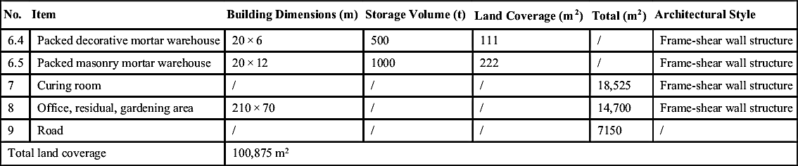
Table 8.55
Main Facilities Involved for Annual Handling Capacity of 1,000,000 t Construction and Demolition Waste in Xi'an City Project
| No. | Main Facilities | Style | Power (kW) | Unit Cost (Dollar) | Total (Dollar) | Note |
| Recycled Aggregate Workshop | ||||||
| 1 | Vibrating feeder | ZSW490 × 110 | 15 | 12,712 | 12,712 | |
| 2 | Jaw crusher | PE900 × 1200 | 110 | 103,188 | 103,188 | |
| 3 | Simmons cone crusher | CSB240 | 240 | 209,368 | 209,368 | |
| 4 | Centrifugal impact crusher | VS I 1140 | 400 | 86,738 | 86,738 | |
| 5 | Circular vibrating screen | 2YA2160 | 30 | 20,937 | 20,937 | |
| 6 | Circular vibrating screen | 3YA2160 | 74 | 22,432 | 44,865 | 2 screens |
| 7 | Vibrating feeder | GZD200 × 120 | 4.4 | 5234 | 5234 | |
| 873.4 | 483,041 | |||||
| Premixed Mortar Workshop | ||||||
| 1 | Dryer | Horizontal | 50 | / | ||
| 2 | Mortar processing line | SHEF-20SJ | 200 | 747,742 | 747,742 | |
| 250 | 747,742 | |||||
| Wallboard-Component Combined Workshop | ||||||
| 1 | 50 blending stations × 4 | 29,910 | 119,639 | |||
| 2 | Recycled aggregate board processing line | SHEF-20BC | 120 | 747,742 | 747,742 | |
| 3 | Recycled aggregate board processing line | SHEF-10 KC | 220 | 299,097 | 299,097 | |
| 340 | 1,166,477 | |||||
| Other | ||||||
| 1 | Belt conveyor | 650 mm | 5.5 | 1,944,129/m | 74,774 | |
| 2 | 5 loaders | Wheel XG951-III | 162 | 59,819 | 299,097 | |
| 167.5 | 373,871 | |||||
| Total | 1630.9 | 2,786,086 | ||||

Table 8.56
Typical Mix Proportion of C30 Concrete
| Material | Cement | Sand | Stone | Fly Ash |
| Amount, kg/m3 | 300 | 700 | 1100 | 100 |
