Understanding vector path components
Defining vector paths
Manipulating vector paths
Creating vector masks
Adding custom vector shape layers to documents
Editing vector shapes
Vector data is completely foreign to most of the other functions in Photoshop that deal with pixel manipulation. Vector paths and shapes are derived from a series of mathematical functions rather than specific values for individual pixels. This chapter focuses on helping you understand how vector paths are created and manipulated as well as how to use them to create selections, masks, and shapes that can be applied to images.
You must understand the nature of paths to utilize them when working in Photoshop. Basically, a path is a series of lines called vectors. Each vector is made up of a coordinate in the image, a value that defines the direction, a value that defines the length, and parabolic parameters that define the contours. Instead of storing an image as a series of pixel values, the path data is stored as a series of mathematical functions that define the vector lines that make up the image.
Using paths has some definite advantages over simple pixel data:
The vector data is common to many different computer graphics applications, so you can save a vector image in one application and then use it and even manipulate it in another without losing any integrity of data. For example, you could create a path shape in Photoshop and then open it in Illustrator and still be able to manipulate it.
Paths can be resized to a much larger size without losing the sharpness. Most fonts are based on vector paths. That is why you can increase the size of the font and still keep the crisp edges.
Vector paths can be easily manipulated several times without generating pixelization.
The following sections discuss the types of paths that can be created in Photoshop as well as the components that make up the path.
Two basic components are involved in creating a path: the line segments and the anchor points. The anchor points fix the end points of each line segment to the canvas below. Each line segment in the path requires one anchor point at each end. However, you can add several anchor points to a path, and a line segment is generated between them using a mathematical function.
The basic function of anchor points in a path is to provide a fixed point that allows a change of direction or curve in the lines. For example, Figure 17.1 displays a simple path with several anchor points. Notice that at each anchor point, the path changes direction.

Figure 17.1. A path is made up of a series of anchor points connected by line segments. The anchor points allow the path to change direction.
The shape of the curve in each line segment is controlled by direction points attached to the anchor points of the line segment, as shown in Figure 17.2. The direction points control the angle at which the line segment leaves the anchor. Between the anchor and the direction point is another line called the direction line, as shown in Figure 17.2.
The length of the direction line denotes how far the line segment moves away from the anchor point before being pulled back into the next anchor point. The longer the direction line, the farther away from the anchor point the line segment moves in that direction before curving back toward the next anchor point, as shown in Figure 17.2.
There are two types of anchor points: corner points and smooth points. Corner points can produce sharp transitions in direction between line segments, while smooth points always produce a smooth transition in the direction between line segments.

Figure 17.2. The direction point and line indicate the direction and how far the line segment moves away from the anchor point before moving back toward the next anchor point.
The direction points in a smooth anchor move simultaneously, so the line segments on both sides of the anchor point are adjusted at the same time. The direction points on a corner anchor move independently, so only one segment attached to the anchor moves at a time. This allows you to create a sharp corner, as shown in Figure 17.3.

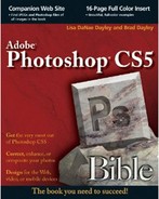
You will work with several different types of paths in Photoshop. We begin working with paths later in this chapter, so you need to understand the different types in the following list:
Linear: Linear paths are simple, straight lines that move directly from one point to another, as shown in Figure 17.4.
Curved: Curved paths are lines that do not move in a straight line from one point to another, but instead follow a parabolic curve, as shown in Figure 17.4.
Open: An open path is a set of one or more lines that has both a starting point and an ending point, as shown in Figure 17.4.
Closed: A closed path is a set of one or more lines that do not have a starting point or an ending point, as shown in Figure 17.4. A closed path is created by placing the end point of the last line in the exact coordinates of the starting point of the first line, creating an entirely closed area. Closed paths are called path components, path shapes, or path layers.
Working: The working path is the current set of paths that you are actively working on that have not yet been saved. You can have only one working path active at a time, so you need to save the path using the Paths panel, discussed later in this chapter, when you are finished with it before you can open another working path.
Clipping: Clipping paths are a special type of path used to control what areas of the image are visible when viewed in a page layout or illustration application. This allows you to hide parts of the image in the final layout without actually deleting those areas of the image.
Note
Paths also can be applied as vector masks. This allows you to create complex paths using the tools described in this chapter and apply them as vector masks to images. See Chapter 10 for information about how masks are used.
When working with vector paths, you utilize several different tools and panels to create, manipulate, and use the paths. The Pen tools allow you to create paths, add points, modify points, and delete points from paths. The Path Selection tools allow you to move entire paths as well as individual points on a path. You use the Paths panel to manage and utilize paths in your documents. This section discusses these tools; in the following section, you learn how to utilize them to create and manipulate vector paths.
The Pen tools, shown in Figure 17.5, allow you to create paths using a Point-to-point and Freehand Pen tool. The Pen tools also allow you to manipulate the path by adding or removing individual points from the path.

Figure 17.5. Using the Pen tools you create paths, add points, modify points, and delete points from paths.
The keyboard shortcut P selects the Pen tools, and Shift+P toggles between the Pen tool and Freeform Pen tool. The follow list describes the purpose of the Pen tools:
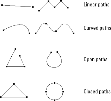
Pen tool: Using this tool, each time you click the document, an anchor point is added and a straight line segment is added between the previous anchor point and the newly created anchor point. The Pen tool can be used to add direction points as you are adding anchor points in a couple of different ways.
You can add points to the path as smooth anchors. When you hold down the mouse button and drag as you add an anchor point, the anchor point is added as a smooth anchor, a set of direction points/lines follows the movement of the mouse, and the new line segment curves according to the direction and length of the direction lines, as shown in Figure 17.6.
Tip
When you hold down the Shift key when you are using the Pen tool, the next anchor is snapped to 45-degree-angle increments. This is useful if you need to keep your path symmetrical or add straight horizontal/vertical lines to your path.
You also can add a direction point to an anchor after you have already added the anchor. When you click an existing anchor (at either end of the path) using the Pen tool, a direction point/line follows the mouse. When you release the mouse, a direction point/line is added to the anchor and the anchor becomes a corner anchor. When you add the next point, the line segment between the two points adheres to the previously added anchor point, as shown in Figure 17.6.
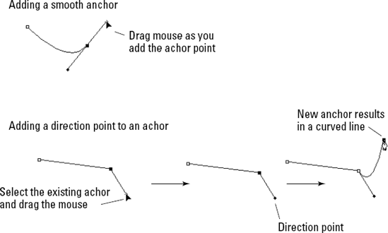
Figure 17.6. Using the Pen tool, you can add simple anchors by clicking the mouse button, add curved anchors by clicking and dragging the mouse, and add corner anchors by dragging an existing anchor to add a single direction point/line.
Tip
For faster manipulation of paths, use the Auto Add/Delete option in the Pen tool. When you hover over an existing path with the Pen tool, the Pen tool toggles between the Add Anchor Pen tool and the Delete Anchor Pen tool. This allows you to use a single tool to add and remove points from the existing path.
Freeform Pen tool: The Freeform Pen tool allows you to use the mouse to freehand a line on the document by clicking and dragging the mouse. As long as you are dragging the mouse, a line is drawn. When you release the mouse, the line is converted to a path with the necessary anchor points, as shown in Figure 17.7.
Magnetic: When the Freeform Pen tool is selected, you see the Magnetic option in the Options menu. When the Magnetic option is selected, the line you draw with the Freeform tool tries to follow the boundaries of edges. This is a great option when you are trying to use the Freehand tool to trace around an object in the background image.
Add Anchor Point tool: The Add Anchor Point tool allows you to add an anchor to an existing path. Simply select the Add Anchor Point tool, and click the path to add the anchor.
Delete Anchor Point tool: The Delete Anchor Point tool allows you to remove anchors from the path by clicking them with the mouse. The line segments on either side of the anchor are combined into a single line segment. Be careful when removing anchors from the path because it may drastically alter the appearance of the path.
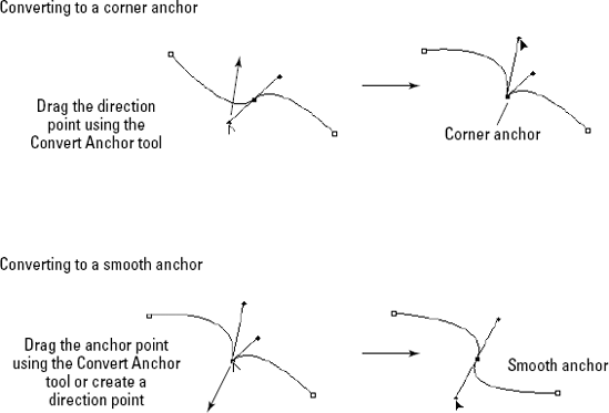
Convert Point tool: The Convert Point tool is used to convert corner anchor points to smooth anchor points and smooth anchor points to corner anchor points.
Smooth anchor points are converted to corner anchor points when you select them with the Convert Point tool. Photoshop displays the direction points and lines that normally move simultaneously. Then you use the Convert Point tool to drag one of the direction points to change the curve across the sharp point to an angle, as shown in Figure 17.8.
Corner anchor points are converted to smooth anchor points when you click them with the Convert Point tool and drag the mouse to add and adjust the direction points and lines that define the curve across the anchor point, as shown in Figure 17.8.
When the Pen tool is selected, several useful options are available in the tool options menu bar, shown in Figure 17.9. The Pen tool options allow you to toggle among Pen, Freeform Pen, and Shape tools; toggle among the Shape, Path, and Fill modes; and define how the path area is generated.

Figure 17.9. Using the Pen tool options, you can set the Pen type and mode and define the path area.
The following list describes the options available for the Pen tool:
Shape Layers/Paths/Fill Pixels modes: These modes allow you to toggle among the shape, path, and fill pixels modes. When Shape Layers is selected, you are drawing to the currently selected shape in the Shapes panel. When Paths is selected, you are drawing to the currently selected path in the Paths panel. When Fill Pixels is selected, you are drawing directly to the currently selected layer.
Pen/Freeform Pen/Shape modes: These modes allow you to toggle among the Pen tool, Freeform Pen tool, Geometric Shapes, lines, and the Custom Shape option. When Custom Shape is selected, you have access to the Shape drop-down menu to select a shape to add to the path.
Rubber Band: When the Rubber Band option is selected, the segment line is drawn and updated while you are adding anchor points. This is an extremely useful feature, but it does use up extra processing power and might be a bit sluggish on slower computers.
Auto Add/Delete: When this option is selected and you hover over an existing path with the Pen tool, the Pen tool toggles between the Add Anchor Pen tool and the Delete Anchor Pen tool. This allows you to use a single tool to add and remove points from the existing path.
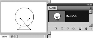
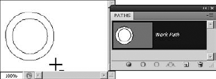
Add to Path Area: When this option is selected, the path you are creating is simply added to the current working path; any overlapping areas are still in the path. Figure 17.10 shows how an open path is added to the current circle path using the Add to Path Area option.
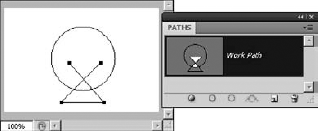
Subtract from Path Area: When this option is selected, the path you are creating is deleted from the current working path—in other words, any overlap is removed from the working path. Figure 17.11 shows how an open path is removed from the current circle path using the Remove from Path Area option.
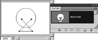
Intersect Path Areas: When this option is selected, the current working path is altered to include only those areas where the original current working path and the newly created path overlap each other. Figure 17.12 shows how an open path is intersected to the current circle path using the Intersect Path Areas option.
Exclude Overlapping Path Areas: When this option is selected, the current working path is altered to include only those areas where the original current working path and the newly created path do NOT overlap each other. Figure 17.13 shows how the exclusion path is created when an open path is intersected by the current circle path using the Exclude Overlapping Path Areas option.

The Path Selection tools, shown in Figure 17.14, allow you to create, move, and manipulate tools. You use these tools to adjust and customize existing paths. You also use these options to combine paths into shapes.
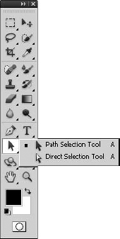
Figure 17.14. Using the Path Selection tools, you can select, move, and scale one or more paths, as well as edit individual anchor and direction points on a path.
The keyboard shortcut A selects the path selection tools, and Shift+A toggles between the Path Selection tool and the Direct Selection tool. The following list describes the purpose of each path selection tool:
Path Selection tool: The Path Selection tool is used to select entire paths or groups of paths. You can use the Path Selection tool to select, move, or scale a single path or several paths. Multiple paths are selected by using the Shift key.
Tip
If you hold down the Alt/Option key while dragging a path with the Path Selection tool, a duplicate of the path is created and you drag the duplicate instead of the original path. This is a great way to create multiple copies of the same simple path.
Direct Selection tool: The Direct Selection tool is used to select one or more individual anchor points on a path. You can use the Direct Selection tool to drag and reposition the anchor points. You also can use the Direct Selection tool to adjust the direction points of the selected anchor to change the curve of the line. You can select and manipulate multiple points on the path by holding down the Shift key as you select the anchor points.
Tip
You can change the Path Selection tool into the Direct Selection tool on the fly by holding down the Ctrl/
Tip
When a path is selected using the Path Selection tool, you can fine-tune the position by using the arrow keys on the keyboard. When one or more anchor points are selected using the Direct Selection tool, you can fine-tune the position of the anchor point using the arrow keys on the keyboard.
When the Path Selection tool is selected, several useful options are available in the tool options menu bar, shown in Figure 17.15. The Path Selection tool options allow you to add a bounding box to the path that contains handles that you can use to scale the path vertically and horizontally. The Path Selection tool options also allow you to define how the path areas combine into the working path. You also can use the Path Selection tool options to quickly align multiple paths.

Figure 17.15. Using the Path Selection tool options, you can add a bounding box, define how paths combine, and align multiple paths.
The following list describes the options available for the Path tool:
Add to Shape Area: When this option is selected, the currently selected paths are added to the shape area; any overlapping areas are still in the resulting shape area. Figure 17.16 shows that adding all of the selected paths to the shape area will include them in the working path.
Subtract from Shape Area: When this option is selected, the currently selected paths are deleted from the current working path—in other words, any overlap is removed from the working path. Figure 17.17 shows how the selected path is removed from the current path created in Figure 7.16 when the Subtract from Shape Area option is selected.
Intersect Shape Areas: When this option is selected, the current working path is altered to include only those areas where all the selected paths and the original working path overlap. This can be a bit tricky until you figure out that all paths including the working path must overlap. Figure 17.18 shows how two selected paths intersect the current working path from Figure 17.16 using the Intersect Shape Areas option. Notice that only the small circle is included in the resulting path, because it is the only part that actually intersects both paths and the working path.
Exclude Overlapping Shape Areas: When this option is selected, the current working path is altered to exclude those areas where all the selected paths and the original working path overlap. This can be a bit tricky until you figure out that all paths including the working path must overlap. Figure 17.19 shows how the intersection of two selected and the current working path from Figure 17.16 is excluded using the Exclude Overlapping Shape Areas option. Notice that the small circle is excluded in the resulting path, because it is the only part that actually intersects both paths and the working path.
Combine: When you click the Combine button, paths that make up the current working area are combined to form a single path set. Figure 17.20 shows how converting the path from Figure 17.17 results in a single path.
Alignment tools: The Alignment tools allow you to align two or more selected paths to the top, right, vertical center, left, right, and horizontal center. These options are useful to arrange paths in exact lines and position them accurately. For example, Figure 17.21 shows two items centered vertical with each other using the Alignment tool.
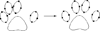
Distribution tools: The Distribution tools allow you to distribute three or more selected paths evenly to the top, right, vertical center, left, bottom, and horizontal center. These options are useful to evenly arrange paths in exact lines and position them accurately. For example, Figure 17.22 shows an example of using the Distribute Horizontal Center option to evenly distribute a set of four paths.
Show Bounding Box: When you select this option, a bounding box is displayed around the selected paths. The bounding box provides handles on each edge, as well as rotation controls at each corner. You can use the bounding box to resize and rotate the selected paths. If you hold down the Shift key, the size adjustments keep the vertical and horizontal proportions, and the rotation is done in 15-degree increments. Figure 17.23 shows an example of using the bounding box to resize and rotate the selected paths.


The Paths panel, shown in Figure 17.24, allows you to manage the current paths in your document. From the Paths panel, you can select paths, convert paths to selections and vice versa, as well as create new paths.

From the Paths panel, you can use the following options:
Fill path with foreground color/Fill Path: This fills the currently selected path with the current foreground color. The path does not need to be closed, but it does need at least two line segments that do not form a straight line.
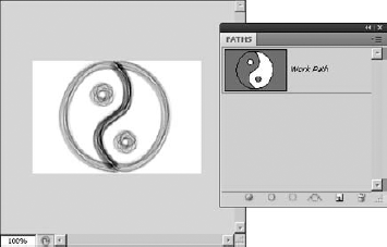
Stroke path with brush/Stroke Path: This option allows you to apply a bitmapped brushstroke to the path. The currently selected brush style and size are used to trace the lines in the path on the image. Even though the path is visible on the screen, it isn't visible in the saved image or in the printed image unless a fill or brushstroke is applied. For example, Figure 17.25 shows an example of the effect on the image when a brushstroke is applied to a path.
Load path as a selection/Make Selection: When you select this option, a new selection is created using the line segments of the currently selected path in the Paths panel. Creating selections from a path is extremely useful for two purposes: You may want to use the capabilities of paths to create and manipulate line segments using the anchors, you may want to apply a path to an image, and you want to alter the pixels below the path before applying it to the image.
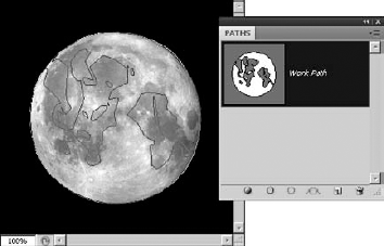
Make working path from selection/Make Work Path: When this option is used, the current selection in the image is converted to a path. This is a great way to create complex paths from existing images. For example, it was easy to select the darker areas of the image of the moon in Figure 17.26 and create a path from them.
Create a path/New Path: When you select this option, a new path is added to the Paths panel and you can begin to add path components to it.
Delete current path: This removes the currently selected path from the document.
Duplicate Path: This creates a copy of the currently selected path and adds it to the Paths panel as a new path.
Clipping Path: This creates a clipping path in the image. The dialog box allows you to set the flatness of the clipping path in terms of device pixels. Printers use the value specified in the flatness field to determine the granularity they look at when applying the clipping path. The lower the flatness field, the crisper the clipping looks. You also can select which path to use for the clipping path.
Panel Options: When you select panel options from the Paths panel menu, a dialog box is displayed allowing you to set the size of the thumbnail used to view the path in the Paths panel list.
Tip
You share paths between documents by selecting them in the Paths panel of one document and then dragging and dropping them into another document window in Photoshop.
In the previous sections, we discussed path components, the vector tools used to create paths, and Paths panel used to manage paths. In this section, we put that knowledge to use in some of the common tasks that you can perform when working with tasks. The following sections take you through some examples of creating and using paths.
The first example we look at is creating a basic path using the following steps:
Select the Pen tool.
Set the mode to Paths in the Pen tool options menu.
Select the Ellipse tool from the Pen tool options menu.
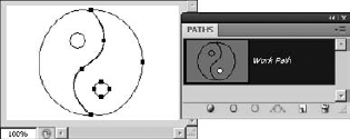
Draw two circles by holding down the Shift key, as shown in Figure 17.27.
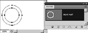
Use the Path Selection tool to select both circles, and then click the Exclude overlapping shape area option in the Path Selection tool options menu to remove the center of the inner circle from the path area.
Click Combine in the Path Selection tool options menu to combine the path, as shown in Figure 17.28.
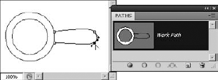
Use the Pen tool to add the points shown in Figure 17.29.
Use the Path Selection tool to move the new path so it touches the existing circles.
Use Convert Point tool to adjust the corners for the handle so they are round by dragging the direction points, as shown in Figure 17.30.
Click each corner to convert the corner to a smooth anchor, and then drag away from the corner to add and shape the curves.
Add the handle to the rest of the shape by using the Path Selection tool to select the handle and clicking the Add to Shape Area button in the options menu.
Select both the handle and the circles, and then click Combine to combine the two areas into a single path, as shown in Figure 17.31.


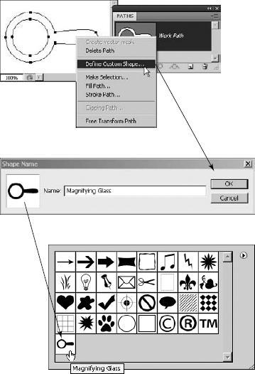
In this example, we convert the path from the previous example into a vector shape using the following steps:
Select the path using the Path Selection tool.
Right-click the selected path to bring up the menu shown in Figure 17.32.
Select Define Custom Shape... from the menu to bring up the Shape name dialog box shown in Figure 17.32.
Name the shape, and click OK to add the new shape to the Custom Vector Shapes menu, as shown in Figure 17.32. You can view the Custom Vector Shapes by selecting Edit

In this example, we create a clipping mask that can be saved with the file to mask any area outside of a specific object when the file is printed:
Open an image in Photoshop.
Use the Pen tool to create a path around an object in the image, as shown in Figure 17.33.
You need to adjust the curved anchor points so the line segments follow the perimeter of the object.
Select the working path in the Paths panel.
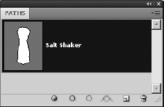
Select Save Path from the Paths panel menu to save the path.
Photoshop doesn't allow you to make a clipping path until you have saved the path. You need to name the path. In this case, we named the path Salt Shaker, as shown in Figure 17.34.
Select Clipping Path... from the Paths panel menu to launch the Clipping Path dialog box shown in Figure 17.35.
Select the saved path, and set the flatness.
In this case, we set the flatness to 5 device pixels to keep the sharpness good enough while still supporting most printers. Flatness determines the number of lines used to draw the curve. A lower flatness value will result in a greater the number of straight lines used to draw the curve and consequently a more accurate curve. Flatness values can range from 0.2 to 100.
Click OK to make the path a clipping path.
Save the file as a format that supports clipping masks, typically EPS or TIFF.
The file is created with the clipping path data.


In this example, we create a vector mask that will be added to a layer to mask part of the pixels using the following steps:
Open an image in Photoshop.
Use the Pen tool to create a path around an object in the image, as shown in Figure 17.36.
In this case, the path is a simple ellipse around the dog's face.
Select Save Path from the Paths panel menu to save the path.
Photoshop doesn't allow you to make a vector mask from the path until you have saved the path, as shown in Figure 17.36.
If you are using a background layer, convert the background to an unlocked layer by double-clicking it, and then select it in the Layers panel, as shown in Figure 17.37.
Select the saved path in the Paths panel so Photoshop uses the selected path to create the vector mask.
Open the Masks panel if it is not already open.
Select the Add vector mask option in the Masks panel to add the vector mask to the image, as shown in Figure 17.37.
The layer mask is added to the layer, and a copy of the layer vector mask is added to the Paths panel.

Note
The image shown in Figure 17.37 can be found on this book's Web site as Figure 17-37.psd. It has a good shape to practice using vector paths to create masks.

The easiest way to describe a vector shape is a vector path applied as a mask to a fill layer. Unlike paths, vector shapes apply pixel data to the document. Vector shapes can be applied to a document either by directly painting the shape pixels onto a layer or as their own layer, called a vector shape layer.
When you use the Fill Pixels option, shown in Figure 17.39, to apply vector shapes to documents, the vector shapes you apply are immediately rasterized and painted onto the pixels in the selected layer in the Layers palette. This replaces the pixel data below them.
When you use the Shape Layers option, also shown in Figure 17.39, to apply vector shapes to documents, the vector shapes are added as vector shape layers. The vector shape layers can be edited later.
This section discusses the vector shape layers, although most of the tools work the same with either the Shape Layer or Fill Pixels option set.
Creating vector shapes is almost identical to creating vector paths with the exception that a color is used to fill in the contents of the vector shape. Vector shapes can be added to a layer either by selecting the Pen tool from the options menu or by selecting one of the vector shapes from the Shape tools in the Toolbox shown in Figure 17.38.
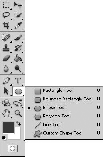
The keyboard shortcut U selects the shape tools, and Shift+U toggles between the Shape tools. When you select a vector shape, a Shape tool options menu similar to the one in Figure 17.39 is displayed. Click the Shape Layers mode to add the vector shapes as shape layers.
Note
The principles you learn in this section using the Shape Layers mode apply the same way to the Fill Pixels mode. The only difference is that in Fill Pixels mode, you are directly writing to the background or layer instead of as a shape layer.
Notice that the Shape tool options menu for Shape Layers mode is almost identical to the Pen tool options menu for Paths mode. It has the same Path, Shape Layers, and Fill Pixels modes, as well as the Add to Shape Area, Subtract from Shape Area, Intersect Shape Areas, and Exclude Overlapping Shape Areas buttons to control how the vector path and shapes interact with each other to create the areas.

Figure 17.39. The Shape tool option menu is identical to the Pen tool option menu. However, when you select the Shape Layers option, additional options are available.
The big difference when using the Shape Layers mode is that because we are adding the vector shapes as a fill layer, we have the following new options:
Create new shape layer: When this option is selected, a new shape layer is created when you use the vector shape tools to draw shapes on the image.
Change layer properties: When this option is selected, the properties of the selected layer are altered when changing the Color or Style option. When this option is not set, the properties of the new layer are changed.
Style: This option allows you to set the style used for the fill from the available Styles palette.
Color: This option specifies the color to use as the background of the fill for the current layer.
In the paths section, we discussed the additional options for the Pen and Freeform Pen tools. So in this section, we discuss only the options available for the vector shape tools. The following list describes the options available in the options menu for each of the Shape tools:
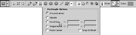
Rectangle: This option creates a rectangle by dragging the mouse between two diagonal corners. Using the Shift key while dragging the mouse creates a square. The Rectangle tool provides the following options by clicking the down arrow next to the custom shape button to open the drop-down shown in Figure 17.40:
Unconstrained: This option allows the rectangle to be created any size.
Square: This option forces the creation of a square instead of a rectangle.
Fixed Size: This option allows you to set the height and width of the rectangle.
Proportional: This option forces the rectangle to match the proportions of the height and width specified.
From Center: Instead of dragging from corner to corner, the first location you select is used as the center and then you select one of the corners to create the rectangle.
Snap to Pixels: This option snaps to the corners to the pixel grid.
Rounded Rectangle: This option creates a rectangle with rounded corners by dragging the mouse between two diagonal corners. Using the Shift key while dragging the mouse creates a square. When this option is selected, a Radius option is available in the options bar that allows you to set the radius of the corners of the rectangle. This option provides the same additional options in the options drop-down as the Rectangle tool.
Ellipse: This option creates an ellipse by dragging the mouse between two diagonal corners. Using the Shift key while dragging the mouse creates a circle. This option provides the same additional options in the options drop-down as the Rectangle tool, with the exception that the Square option is a Circle option and there is no Snap to Pixels option.
Polygon: This option creates a polygon with the number of sides specified by the additional Sides option. The polygon is created by dragging the mouse between two diagonal corners. Using the Shift key while dragging the mouse forces the polygon to 45-degree angles. The Polygon tool provides the following options from the options drop-down shown in Figure 17.41:
Radius: This option allows you to set the radius of the polygon in inches.
Smooth Corners: When this option is selected, the corners of the polygon are smooth anchors instead of corner anchors.
Star: When this option is selected, the line segments between the corner anchors of the polygon are indented toward the center by the amount specified by the Indent Side By setting.
Smooth Indents: When this option is selected, the corners of the indents are smooth anchors instead of corner anchors.
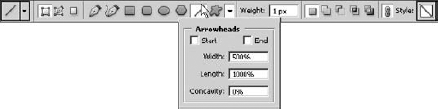
Line: This option creates a line with the thickness specified by the additional Weight option. The line is created by dragging the mouse between two points. Using the Shift key while dragging the mouse forces the line to 45-degree angles. The Line tool provides the following arrowhead options from the options drop-down shown in Figure 17.42:
Start: When this option is selected, an arrowhead is added to the first point selected.
End: When this option is selected, an arrowhead is added to the last point selected.
Width: This specifies the width of the arrowhead relative to the weight of the line.
Length: This specifies the length of the arrowhead relative to the weight of the line.
Concavity: This specifies how concave to make the arrowhead relative to the weight of the line.
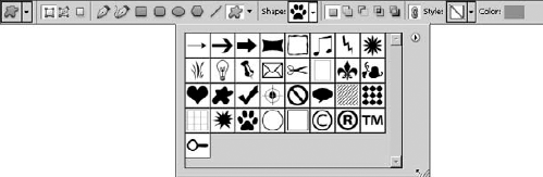
Custom Shape: This option creates a custom shape selected from the additional Shape option shown in Figure 17.43. The custom shape is added to the image by selecting a shape from the list and then dragging the mouse between two diagonal corners. Using the Shift key while dragging the mouse creates the shape in even proportions.

Now that you have a good understanding of the available vector shape tools from the previous section, you should try adding a few to a document to get the hang of it. The following examples take you quickly through the steps to add the vector tools in a few different ways.
The first example we look at is just creating a simple square by keeping the Rectangle tool in proportion using the Shift key. The technique here is similar for creating all the vector shapes in proportion. Use the following steps:
Select the Rectangle tool from the Toolbox.
Click the Shape Layers option in the options bar to create a new layer with the shape.
Hold down the Shift key and drag diagonally across the screen to create the square, as shown in Figure 17.44.
Notice that the shape is forced into a square and that a new shape layer is added to the Layers panel.

In the next example, we look at using the Polygon tool to add an eight-sided star with an overspray technique to give it more depth. Use the following steps:
Select the Polygon tool from the Toolbox.
Click the Shape Layers option in the options bar to create a new layer with the shape.
Select the Smooth Corners, Star, and Smooth Indents options from the Polygon tool options, as shown in Figure 17.41. Also set the Indent Sides By option to 50%.
This makes the polygon a star with smooth corners and indents.
Set the Sides option in the options bar to 8 to create an eight-sided polygon.
Select the Overspray Text style from the Style option in the options bar to add the overspray effect to the polygon.
Position the mouse in the center location for the polygon, and click and drag the mouse out to create the polygon shown in Figure 17.45.
Notice that the polygon Shape layer has the Bevel and Emboss and Satin effects applied to create the overspray effect.

Figure 17.45. Selecting the Smooth Corners, Star, and Smooth Indents options for a polygon creates a star-shaped polygon. Selecting the Overspray Text option in the Style options applies a bevel effect.
The final example we show uses the Exclude Overlapping Shape Areas option to combine the polygon created in the previous example with a circle to create a completely different shape. Use the following steps after completing the steps from the previous example:
Select the Ellipse tool from the Shape tool menu.
Select the From Center option from the Ellipse tool options drop-down menu.
This allows you to use the center of the polygon as the starting point, which is much easier than trying to figure out where the corner of the ellipse is.
Select the Exclude Overlapping Shape Areas option from the options bar so only the areas of the circle that are outside the polygon are included in the new shape area.
Position the mouse in the center of the polygon, hold down the Shift key, and drag outward to create the circle, as shown in Figure 17.46.
Notice that only the area outside of the polygon is included in the shape area shown in the Layers panel.
Use the Path Selection tool to select the circle, and then use the keyboard arrow keys to reposition the circle so it is exactly around the perimeter of the polygon.

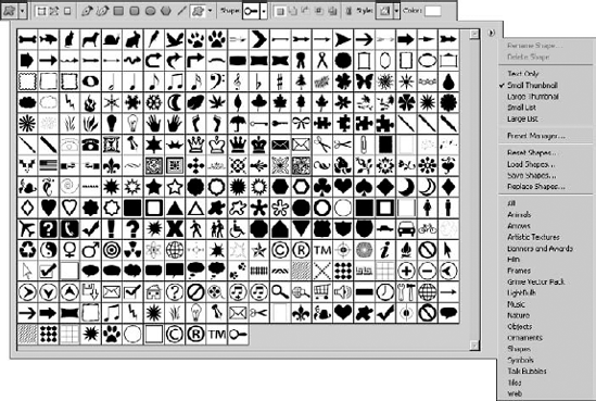
Adding custom vector shapes works the same way as adding the normal vector shapes, with the exception that you have some additional options in managing the custom shapes from the Shape Selection options in the Shape options menu shown in Figure 17.47. When you select the drop-down arrow, the Shapes list shown in Figure 17.47 is displayed. You can select any shape, and when you click and drag the mouse on the document, the shape is added just as in the previous examples.
The Shapes list provides a side menu, also shown in Figure 17.47, that includes the following options:
Rename Shape: This option brings up a dialog box allowing you to change the name of the selected shape. The name appears when you hover over the shape in the tool and in some of the other panels in Photoshop.
Delete Shape: This option deletes the currently selected shape from the Shapes list.
View Options: This option allows you to set the mode for viewing shapes. You can select Text Only, which displays only the shape names, three sizes of thumbnails, or two sizes of list views. The list views include a thumbnail as well as the shape name.
Preset Manager: This option launches the preset manager with the Custom Shapes option selected, where you can create and manage presets for the Custom Shapes list.
Reset Shapes: This option replaces the current list of shapes with the default list.
Load Shapes: This option allows you to load a set of shapes from a previously saved file. The new shapes are added to the current list of shapes.
Save Shapes: This option allows you to save the current set of shapes as a file. This is useful if you are creating your own custom shapes so you have them available later and can distribute them to others.
Replace Shapes: This option allows you to load a set of shapes from a previously saved file. The current list of shapes is replaced by the new list.
Preset Lists: This option provides several preset lists of shapes that make it easier to find shapes you want. You can select any of them from the list, and the current Shapes list is replaced by the selected preset list.
A great feature of vector shape is that they include the anchor and line information from the vector paths that created them. This allows you to edit the vector shapes after you have added them to your document. The following example takes you through adding a custom shape to a document and then editing it with the Vector tools:
Select the Custom Shape tool from the main menu.
Click the Shapes Layers option in the options bar to create a new layer when the shape is added.
Select the Heart Card shape from the Shapes list in the options bar.
The Heart Card shape is in the Shapes preset list in the preset manager.
Use the mouse to drag diagonally to add the heart to the document.
Select the Direct Selection tool from the Toolbox, and click the heart to expose the anchors, as shown in Figure 17.48.
Use the Direct Selection tool to drag the bottom anchor points of the heart, as shown in Figure 17.48.
Use the Direct Selection tool to adjust the direction points of the curve, as shown in Figure 17.48, to give the heart a new look.
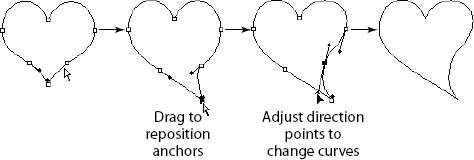
Figure 17.48. Shapes contain the vector anchor and line information of the vector paths used to create them so you can edit a vector shape at any time using the vector path tools.
Note
You cannot edit vector shapes that are applied to a document using the Fill Pixels option in the Shape tool options menu because the vector shape is rasterized into pixel data and painted onto the layer.
This chapter discussed how to create and manipulate vector paths and shapes. Vector paths provide a distinct advantage over pixel data because you can resize them without losing any of the crispness of data. That makes them useful for creating shapes, masks, and selections that can be resized without losing the sharpness in the edges. Vector shapes layers are vector shapes applied as masks to a fill layer.
In this chapter, you learned these concepts:
How to create a vector path using the vector path tools.
You can manipulate individual anchor points on a path to define the position of line end points and the curvature of the line.
How to create a clipping mask.
Creating a vector mask provides a mask that can be manipulated using the vector path tools while maintaining its crisp edges.
Adding stroke and fill to a vector path makes the path visible in the image.
How to create a vector shape from a vector path.
How to edit vector shapes after they have been added to an image.