
We noted in Chapter 1, “A Brief History of Object-Relational Mapping,” that this book is largely about the divide that exists between the world of relational databases and object-oriented programming. This fundamental divide can be bridged (or “mapped”) with many different techniques and approaches. The specifics of how you bridge this gap is crucial to answering the question about why one persistence framework is better than another for SOA application styles, such as those outlined in Chapter 2, “High-Level Requirements and Persistence.” In other words, whereas Chapter 2 is about high-level requirements, this chapter is about detailed design.
This chapter introduces some fundamentals and best practices of domain modeling with respect to persistence, as well as some common strategies of mapping a domain model to a database with an example-driven approach. The primary example showcased—a customer order management system—sets the stage for the evaluations in the rest of this book. The common example’s domain model, along with its corresponding database schema, is used in Chapters 5 through 9 to illustrate the details of how to use the object-relational technologies surveyed.
Chapter 1’s historical overview of the evolution of object-relational mapping solutions showed that there are a number of common concepts between the different solutions, and that these same features and concepts have emerged in different languages and products over the years. One of the most important lessons learned over the past two decades in software engineering not discussed in Chapter 1 is that such recurring concepts can be expressed in the form of “patterns”—reusable solutions to common problems.
Patterns are described in a context of a problem and the associated forces at play that make the pattern approach the best choice in that situation. Patterns from a related set of problems form a vocabulary that developers can use to discuss concepts in a field; and they also form a basis for comparison of different approaches. For instance, you can describe an ORM product by referring to the patterns that it implements; similarly, you can compare two ORM products by contrasting the different pattern choices that they implement and the trade-offs they make.
The first pattern language describing object-relational mapping was published in the Pattern Languages of Program Design, volume 2 [Vlissides]; but for the purposes of this chapter, we will refer to a later pattern catalog covering patterns of ORM: Martin Fowler’s Patterns of Enterprise Application Architecture [Fowler]. Fowler’s patterns have the advantage of being a complete set, while at the same time being easy to understand and to identify when seen in context. Keep in mind that this chapter only introduces these patterns in the context of a survey of the features of ORM, and is not providing a complete coverage of the subject.
The most fundamental of these ORM patterns is the Domain Model pattern. Every enterprise system has a context under which it operates. This context is its “domain.” A domain can be characterized and modeled as a set of related objects with both behavior and data, each representing a basic concept. We discussed in Chapter 2 how these domains are often organized around various “aspects” of the IT requirements. For example, some “functional” domains are concerned with concrete real-world objects, such as the products that retail customers can buy. Other functional domains are centered around abstract objects that have no physical manifestation, such as the electronic invoices from a shipping company. There are cases in which domains focus on an aspect that is purely technical (or “nonfunctional”). For example, an application component that serves as a connector between a newly developed order entry subsystem and a legacy credit check system has a domain concerned with the interfaces expected by the two systems. Its “function” is to map the interfaces expected by the internal system to those expected by the external one, each modeled separately.
Providing connectivity such as this is the key problem of object-relational mapping in Java applications—how do you relate a domain of objects often modeled as Plain Old Java Objects (POJOs) to a domain of information modeled as tables, rows, and columns of a relational database? Making this connection is the job of a Data Mapper, which is a key component of the Domain Model pattern. A Data Mapper is a layer of software (not just a single class or object) that fulfills the responsibility of moving information between the domain objects and the relational database at runtime. Performing this Data Mapper function is the primary role of a persistence mechanism. From one perspective, a Data Mapper is simply a black box—you don’t need to look too closely to see how it works; it should just perform its mapping without the need for significant intervention. However, understanding the details of how the Data Mapper function operates is important to both using extensions or advanced features of a particular persistence mechanism, and to comparing different ones.
For example, the simplest technique is to manually populate Java objects with information from relational queries—in effect, hard-coding the object-relational mapping in your application. The majority of systems built with 4GL tooling use this approach, and it is often the quickest solution for small or situational projects. Unfortunately, this approach is nearly always an anti-pattern for a complete enterprise system because the persistence code generated from 4GL tooling is rarely flexible enough to handle the ongoing needs of such a complex system.
Said another way, we have seen countless projects fail due to poor domain modeling. There seems to be a common misconception that a domain model can be created by an architect and/or business analyst in an afternoon with a graphical drawing tool like Visio, and then thrown over the fence to development to be used unmodified for the remainder of the project. More often than not, these models are completely ignored by development because they do not reflect the nature of the implementation technology and are therefore difficult to map efficiently. Successful model-driven design takes good discipline, and there are some best practices that should be followed to stay on the right path, which are covered in the following sections.
Have you ever had to work on a new software project with nothing to learn by except thousands, even millions, of lines of someone else’s source code? If so, you have firsthand experience in dealing with the complexity of enterprise software. The only solution to handling this complexity is to abstract away the details. For example, in such a situation, you may write down the interfaces used in a particular Java package in shorthand to learn about the system. This shorthand is one example of a model. In general, a model is a representation of a complex system that abstracts away unnecessary detail so that you can more easily conceptualize the most important characteristics of the system. A city map is a model. A city map does not include the location of every street lamp or traffic signal. These unnecessary details are abstracted so only the most important information is conveyed to the map’s reader.
In today’s IT world, the Unified Modeling Language (UML) is often used to provide a graphical description of the domain objects and their relationships. Consider the partial domain model of an order management system illustrated in UML, as shown in Figure 3.1.
Although this book is not intended to be a complete tutorial on UML (see [Booch] for a good reference), Figure 3.1 shows that a line item belongs to (or is “contained in”) an order, and that each line item is associated with (or “refers to”) a product. This domain model is an abstraction from the perspective of both a subject matter expert—such as an order packer in the warehouse—and a developer working on the software. From a packer’s perspective, the domain model does not include countless details, such as the construction techniques used in the warehouse or the color of the walls. These details are not usually important to a packer in general, so they are omitted from most domain models. Conversely, from a developer’s perspective, the domain model does not include countless details about the software implementation, such as code frameworks used or user interface constructs. These implementation details are subject to change and add little value to the domain model.
Figure 3.2 illustrates the nature of the abstraction that occurs when designing a domain model. A domain model lives at the intersection of the domain knowledge of subject matter experts and the implementation knowledge of the development team. In fact, a good domain model becomes a common language for communication. Throughout the lifetime of an enterprise application, all parties involved should use the objects described in the domain model as a language to talk about the project. When a project stakeholder encounters a circumstance where this common language is insufficient or limiting, this is a sure sign that the domain model should be modified to create a deeper, richer model to reflect the needs of the stakeholders in communicating about the application. This approach of keeping a domain model in sync with the application’s implementation throughout its lifetime is often referred to as model-driven design.
A common anti-pattern is for an architect to create a domain model without consulting anyone outside of the development team. Subject matter experts and end users should be given equal responsibility for the design of a domain model in comparison to the development team. For example, if a new requirement presents itself to track the status of orders that are submitted until they are shipped, the packer should be involved in the modification of the domain model to ensure that it reflects their understanding of this new application function. If this is not done, the domain model can cease to be intuitive to the system’s subject matter experts, and it does not provide a common vocabulary. Worse, it is likely that requirements will be communicated incorrectly to the development team.
We have encountered organizations that attempt to model every single class and interface in their application code to facilitate communication with the development team about the design. This design-specific view is not an effective way to model enterprise applications. Remember that a functional domain model is first and foremost an abstraction to facilitate communication about what the system needs to do. Imagine trying to use a UML class diagram that includes design patterns such as the session facade and helper class, as described by Brown et al. in their book on J2EE design patterns [Brown], to discuss the new order tracking requirement described previously. Would that UML model be useful to the discussion? Would the names of these extra classes provide a practical common language between development and the subject matter experts? Such a diagram quickly becomes cluttered, inflexible, and too complex even for the development team to conceptualize—especially as designs change.
UML that maps directly to application design can be useful for code generation and as a tool for the development team; however, if you want to practice model-driven design, a separate simplified domain model should be maintained that is referenced and utilized by all the stakeholders of the project. Generators can be made to transform each entity and its associations from the domain model to multiple classes and associations in the design model. These kinds of generators are often referred to as model-to-model (M2M) transformations. Without going into too much detail, M2M transformations capture design trade-offs and can be modeled independently from the functional aspects to facilitate communication between the design and implementation teams. The generated design models can then be used to drive tools to generate the implementation code; these tools are sometimes referred to as model-to-text (M2T) transforms. Having the domain model drive the generation of the design model, and in turn having the design model drive the generation of the implementation, can accelerate development even further. This approach is an application of the Divide and Conquer strategy we discussed in Chapter 2. Furthermore, this process is fundamental to Model Driven Architecture (MDA) and Model Driven Development (MDD). There are many aspects to consider with MDA and MDD that are beyond the scope of this book. Alan Brown’s article [A.3.1] and the Object Management Group’s MDA website [MDA] are good references on this topic for those interested in a deeper dive.
Formal domain models are not necessary for every project. The most common examples are applications that are small or use a very rigid underlying framework, such as an application that utilizes PeopleSoft or SAP packaged software. In these situations, the development team can do very well with 4GL type tooling and ad hoc development without a formal domain model. And it is worth mentioning that in the Web 2.0 space there has been an increase in these small applications, referred to as situational applications. Unfortunately, when small software projects are successful, there is a tendency to enhance them or extend their functionality. Scaling such projects is an enormous risk, and after a significant software system is built without modeling, it is often not possible to create a workable domain model for more disciplined development in the future unless the system is completely reverse engineered.
Domain models should change as an application changes. If there is a requirement to change the application in a way that is difficult to represent in the domain model, that usually means the model needs to be changed—perhaps drastically. Making the effort to enhance and deepen the domain model to handle the new requirement will be well worth your time. In the long term, with subsequent releases of the application, the domain model may change so much that it is unrecognizable compared to its original incarnation. This is desirable, as long as it reflects the current requirements and truly serves as the “language of communication” between the stakeholders and the implementers.
Of course, there are other patterns and best practices related to domain modeling, but many need to be discussed in the context of a concrete scenario for the details to be understood. And for the purposes of this book, we will use a common example as a context for illustrating more specific ORM issues and approaches in this chapter, and reuse this example to evaluate various persistence mechanisms in later chapters.
When choosing a use case, we like to pick one that has enough complexity to illustrate the major features being used in practice or compared. For example, rather than picking a simple “CRUD”-type use case to create, retrieve, update, and destroy a data simple object like a LineItem, it is better to pick some use case that accesses a number of data objects with some interesting business rules, such as processing an Order submitted by a Customer who has poor credit.
The components of a common example and the benefits of each include the following:
Common Domain Model and Database Schema, Constraints, and Normalization Approach—. The example should define a domain model and database schema that is strictly followed during the evaluation of the ORM. Having both domain model and database schema defined provides a well-defined set of endpoints. These endpoints ensure an apples-to-apples comparison as the ORM frameworks under evaluation are exercised with the exact same domain objects and database tables. We will use the common example developed here in the second half of this book.
Common Service Interfaces—. It is also best to provide a clear separation of concerns by exposing an interface with a specific set of services that interact with underlying persistence mechanisms. Separating the underlying implementation from the client with well-defined interfaces illustrates how a particular ORM technology can be encapsulated and componentized. And because all the code examples for the different ORM technologies implement these services, the reader can quickly compare the programming models of the different frameworks.
Common Test Cases—. One of the major lessons learned from the Agile community is a discipline sometimes called “test first design.” We like to repeat the phrase said by our good friend Stacy Joines in her book on performance [Joines]: “Test early and often.” Specifically, after interfaces to a set of persistence services are created and agreed to, the next step is to provide a set of test cases designed to verify that the implementation meets the functional and quality of service requirements of the application (as described in Chapter 2). These test cases become the figurative “voice of the user” for the developer to use during the implementation.
Figure 3.3 introduces the domain model of a customer order management application that serves as a recurring example throughout this book. The intent of this example is to represent the persistence tier of an enterprise Java application. Its domain model is based on real-world object-relational systems we have consulted on across various industries. Although it is necessarily brief, Figure 3.3 provides enough of a domain model to illustrate object-relational mapping concepts throughout the balance of the book. Hereafter, it is referred to as the “common example.”
The domain model stems from a retail business that sells commodity products to end-consumers. The retailer sells to two primary customer segments: business customers and residential customers. Although its products are available to both segments, to entice business customers who tend to place more orders, the system gives special pricing and ordering policies to the business customer segment. A vital business function of the system is to take orders. Accordingly, taking orders is the primary theme for the example application—it stores orders transactionally and provides the functionality to locate and update them.
Specifically, Figure 3.4 shows Abstract Customer as an object that generalizes both business customers and residential customers using UML’s generalization association denoted by the triangular shaped arrows. Notice that they are unidirectional and both point to AbstractCustomer, indicating that both residential and business customers share the attributes of AbstractCustomer. More about generalization is discussed in a subsequent section on inheritance.
Figure 3.5 illustrates two different associations between Customer and Order, which is a bit more interesting. Notice that a Customer has a Set of Orders. This Set contains all the Orders in the system for the Customer. It may include Orders in any state (OPEN, SUBMITTED, or CLOSED). Correspondingly, an order within this Set can access its respective Customer by referencing its customer : AbstractCustomer attribute. This association between a customer and its orders is denoted by the solid line labeled “all.” The customer uses this relationship to access all its orders. It is a UML bidirectional association—both a Customer and an Order can traverse the relationship.
The second relationship, labeled as “open,” signifies a customer’s reference to an open Order. The Customer accesses its open Order by utilizing the openOrder : Order attribute. The cardinality is specified as 0..1 for Order in this association, indicating that it is optional for a Customer to have an associated open Order. The openOrder association is unidirectional and is navigated only through the Customer object. This limitation is reasonable because navigation from Order to Customer is possible through the first relationship.
The reason for modeling the two separate relationships is to help enforce constraints and optimize the access. For example, a web page might always show the customer data and any open order; however, the Set of all Orders might be accessed only by using a history page.
It is a good practice to specify relationships as strictly as possible in domain modeling. We’ve seen UML diagrams drawn using bidirectional relationships without cardinality, composition, or aggregation, which leaves a lot open to interpretation. Loosely defined domain models often lead to miscommunication and increased implementation complexity. Of course, in practice, having a strictly defined domain model is not always possible—especially if you change your domain model often (as should be the case).
Key Point
Strive to design a domain model with associations and types that are defined as precisely as possible.
The order status : Status attribute could easily be modeled as a String; however, this would not provide information about the expected values. To define the domain model as precisely as possible, we employed an enumeration with the possible values of OPEN, SUBMITTED, or CLOSED. The model uses the UML notation with a solid diamond referred to as a composition association. The use of composition implies that the Status enumeration is in fact part of the Order, and that the status has no existence outside of the Order. Naturally, because the enumeration belongs to a particular Order, this is a unidirectional 1:1 association.
Unidirectional associations should be used wherever possible to reduce the coupling of the associated types in object systems.
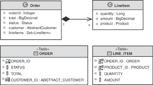
As shown in Figure 3.6, an Order has a Set of LineItem objects representing the products being ordered by the customer. This is again using a UML composition association as all the LineItems are in fact part of or belong to the Order. In object-oriented programming terms, this means that only that particular Order can hold a reference to its LineItem objects. The association is unidirectional and thus can be navigated only through the Order can navigate it. A LineItem has no explicit reference back to its owning Order.
Figure 3.7 illustrates a new directional association called an aggregation—denoted by the hollow diamond. This means that the LineItem is made up of a Product similar to a composition relationship (the solid diamond). The difference from a composition is that the LineItem does not claim ownership over the Product. Should a LineItem be removed from the domain model, the Product remains as it is used independent of the LineItem. Considering that it is a directional association, a LineItem can navigate the aggregation to access its respective Product; however, a Product has no reference to any LineItem instances.
This section describes the database schema for the common example. As with most enterprise applications, the relational entities used at the database schema layer fundamentally differ from the domain objects used in the domain model.
Figure 3.8 shows an entity-relationship (E-R) diagram that models the database schema for the common example. The data types shown (SMALLINT, VARCHAR, and so forth) correspond to those supported by Apache Derby. See Appendix A, “Setting Up the Common Example,” for more information on Apache Derby and a tutorial detailing how to set up Apache Derby with this database schema.
Although the best of all possible worlds (from both an object and a database modeling perspective) is to have the domain model and the database schema be very closely aligned, this is usually not the case in the real world. Most applications are not “greenfield” ones that allow the designers of the object model and the database schema to start from scratch. It is more common that new applications are built atop existing database schemas. Often these schemas were built from a different viewpoint, with a different domain model. In addition, database design takes factors such as physical storage, servicing multiple applications, and other design-specific issues into account. This difference leads to the necessity of meet-in-the-middle mapping. Meet-in-the-middle object-relational mapping is required to use this database schema while keeping the domain model intact. This topic is covered in detail in the section “Object-Relational Mapping.”
The most glaring difference in the E-R diagram compared to the domain model is how the customer information is consolidated into one table. You probably also noticed that there are fewer entities than there were objects in the domain model; for example, there is no direct representation of ProductDirectory or AbstractCustomer. Some more subtle differences are that the LINE_ITEM table has an additional ORDER_ID field referencing its ORDER, the enumeration has been flattened to a VARCHAR data type, and all Boolean attributes are represented as single characters denoted by CHAR(1).
The causes and implications of these mismatches are explored in the section titled “The Object-Relational Mapping Impedance Mismatch Revisited.” For instance, the superclass inheritance mapping strategy necessary to map the CUSTOMER table to the three Customer objects in our domain model is covered in detail later.
Utilizing database constraints such as relational constraints, check constraints, and in some cases database triggers, has long been known as a best practice to maintain data integrity [Ramakrishnan]. Although rarely achievable, it should be the goal of a database administrator to configure a database schema such that its data cannot be in an incorrect state. With the help of database check constraints, we have provided some modest protection against data corruption. Check constraint 2 in Figure 3.8 enforces CHAR(1) data type fields (representing Booleans in our domain model) to accept only “Y” and “N.” For instance, an “A” character should not be inserted into the BUSINESS_VOLUME_DISCOUNT field. Without such constraints, an application can easily insert invalid data into the database—perhaps inadvertently.
All table fields in the schema employ NOT NULL constraints except those in the CUSTOMER table. This is because the CUSTOMER table is sparse—meaning it is acceptable for some fields to be NULL. The other check constraint on the CUSTOMER table shown in Figure 3.8, check constraint 1, ensures that fields in the CUSTOMER table are inserted or updated to NULL appropriately. For example, when a business customer is inserted as a row into the table, the residential fields should be NULL and none of the business fields should be NULL. The opposite applies when a residential customer is inserted.
Check constraint 3 shown in Figure 3.8 similarly enforces that the STATUS field is restricted to OPEN, SUBMITTED, or CLOSED. There is a copy of the DDL schema in each of the projects of the sample code. You can find instructions for downloading and setting up the example in Appendix A.
Database normalization emerged out of the work of the famous British database theorist Edgar Frank Codd [Codd]. It prescribes a process of reducing redundancy and anomalies in a relational database schema by following five normal forms (NF). In practice, only the first three normal forms are used. In addition, a stronger variant of the third normal form, called Boyce-Codd normal form, is popular. The fourth and fifth normal forms deal with cases of multivalued dependencies and many-to-many relationships. The customer order database schema is normalized to Boyce-Codd normal form. Before we inspect the normalization of the customer order relational entities, consider the following definitions:
First Normal Form (1NF)—. For a schema to be in first normal form, database fields must hold an atomic value, or primitive type, and tables must have a primary key. First normal form prevents redundant rows. It also makes a row identifiable by the primary key.
Second Normal Form (2NF)—. A schema is in second normal form if and only if it is in 1NF and all fields are dependent on all the primary key fields such that this dependency cannot be reduced.
Third Normal Form (3NF)—. Third normal form adds the requirement to 2NF that all nonkey fields are dependent on candidate keys alone and not on any nonkey fields. 3NF was famously described by [Kent] this way: “The relation is based on the key, the whole key, and nothing but the key.”
Note: A candidate key is a type that could serve as an alternate key for the database entity.
Boyce-Codd normal form (BCNF)—. Boyce-Codd normal form is a stronger variation of 3NF. A schema is in BCNF if and only if it is in 3NF and the only determinants are the candidate keys. That is, only a key can have a relationship with a nonkey field such that it determines its value.
This is a necessarily brief summary of normal forms; 5NF and 6NF are occasionally used and several other variants exist. For a more complete and detailed introduction to database normalization, see [Date].
The customer order schema is so simple that it is almost intuitively normalized. For instance, most of the tables have a single key for which dependent fields follow naturally. However, it is not very difficult to breach normalization even with such a simple schema. Many database systems allow for a table to be created without a primary key, which breaches 1NF. Organizations often do this in search of performance gains. We strongly discourage this approach because it opens the door to all sorts of data corruption. The difference in performance is often negligible for modern database systems, and there is almost always a better way to improve performance, such as creating indexes, reduction of network latency, or batch processing.
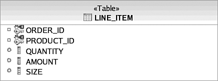
As an example of an entity that breaches 2NF, consider Figure 3.9. Notice that the LINE_ITEM table has a new SIZE field that specifies the size of the purchased product. This may seem like a natural place for it because the size is selected by the end user when the LineItem Object is created for their Order. However, if you look closely, the SIZE field really only depends on PRODUCT_ID and not ORDER_ID (assuming that there is a different PRODUCT_ID for each product size). This breaches 2NF because SIZE is not dependent on the entire key. To remedy this, the SIZE field should be moved to the Product table.
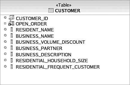
Consider Figure 3.10, which illustrates a modified version of the Customer entity where the NAME field has been expanded to two different fields—RESIDENT_NAME and BUSINESS_NAME. This breaches 3NF and BCNF because the primary key, CUSTOMER_ID, is not a sole determinant of the BUSINESS_VOLUME_DISCOUNT, BUSINESS_PARTNER, and BUSINESS_DESCRIPTION fields. The fields are also determined by the BUSINESS_NAME field, assuming that all business names are unique. To achieve normalization in this situation, the business fields should be separated into their own table with BUSINESS_NAME as the primary key. Notice that this is not the case for the residential fields because residential customers may share the same name. Thus, the residential fields still solely depend on the CUSTOMER key.
In addition to a database schema and domain model, the common example exposes a series of services from its persistence layer. These services serve as an interface decoupling the persistence tier of the system from presentation and business logic.
Figure 3.11 illustrates the three tiers of well-architected enterprise applications. The purpose of the common example is to showcase an example of a persistence tier that implements the persistence interface. This interface completely abstracts the object-relational technology used, as well as the datastore. Should the business tier of another application need to use the objects from the domain model of the common example, it can do so by using this interface. Thus, the business tier can change without affecting the persistence tier. This is also the case for the interface between the persistence tier and the business tier. If a different user interface is needed, the change can be made without affecting the business tier as long as the interface between the two tiers is honored.
Listing 3.1 shows an interface exposing five operations from the persistence tier of the common example: openOrder(), addLineItem(), removeLineItem(), submit(), and loadCustomer(). This is of course only a subset of what is needed for the persistence tier; however, it is suitable for our common example.
Example 3.1. Java Interface for Common Example
public interface CustomerOrderServices {

public Order openOrder(int customerId)
throws CustomerDoesNotExist,
       OrderAlreadyOpen,
       GeneralPersistenceException;

public LineItem addLineItem(int customerId,
                            int productId,
                            long quantity)
throws CustomerDoesNotExist,
       OrderNotOpen,
       ProductDoesNotExist,
       GeneralPersistenceException;

public void removeLineItem(int customerId,int productId )
throws CustomerDoesNotExistException,
       OrderNotOpenException,
       ProductDoesNotExistException,
       NoLineItemsException,
       GeneralPersistenceException;

public void submit(int orderId)
throws CustomerDoesNotExist, OrderNotOpen, NoLineItems,
       GeneralPersistenceException;

public Customer loadCustomer(int customerId)
throws CustomerDoesNotExist,
       GeneralPersistenceException;

}
Figure 3.12 illustrates the usage pattern for three operations of the service. A new Order is created for a given Customer with the openOrder() operation. LineItems are added to that Order with the addLineItem() operation (removeLineItem is similar to addLineItem). Then, the Order can be submitted using the submit() operation. The submit() operation throws an error if there is an attempt to submit an Order without LineItems.
The loadCustomer() operation (omitted from the state diagram in Figure 3.12) is used to load the Customer in its current state. For example, if the Customer has an open Order, then it will load that Order as well as any LineItem objects associated with that Order.
Some people like to wait until after the code is completed to begin writing test cases. Some write them in parallel with the code under test, after the interfaces are defined. But because there is no standardized declarative language for describing the formal semantics of a service operation’s business logic, we consider test cases an important part of understanding the requirements of an application.
These detailed requirements include the domain model and database schema, which provide fixed reference endpoints for the data used by the application’s business logic. The service interfaces provide a fixed reference point for access to the business logic from Java, but by themselves do not describe what each service operation is intended to do. Test cases provide an “operational” semantics that can be verified at runtime to ensure that the code behaves in the required manner.
For the purposes of illustration, we provide one “JUnit” style test case for the CustomerOrderServices, with one or more methods used to test each operation.
JUnit is a unit testing framework for the Java programming language. Created by Kent Beck and Erich Gamma, JUnit is one of, and arguably the most successful of, the xUnit family of frameworks that originated with Kent Beck’s SUnit. JUnit has spawned its own ecosystem of JUnit extensions. “Junit” is also used as a synonym for “unit tests,” as in, “Did you run the junits before you checked in?”
Experience gained with JUnit has been important in the development of test-driven development, and as a result, some knowledge of JUnit is often presumed in discussions of test-driven development, for example in the book by [Beck].
One extension of JUnit is DbUnit. DbUnit is targeted for database-driven projects that, among other things, put your database into a known state between test runs. This is an excellent way to avoid the myriad of problems that can occur when one test case corrupts the database and causes subsequent tests to fail or exacerbate the damage. DbUnit is an open-source framework created by Manuel Laflamme.
DbUnit has the capability to export and import your database data to and from XML datasets. Since version 2.0, DbUnit can work with very large datasets when used in streaming mode. DbUnit can also help you verify that your database data matches the expected set of values.
See Listing 3.2 for the high-level structure of the CustomerOrderServicesTest object—a subclass of the DbUnit class DBTestCase. We include just enough in the following listings to show the essential details of testing an object service that accesses persistent data; the Download site will include the full code example, and Appendix A describes how to run the test case for each of the five persistence mechanisms under test.
Example 3.2. High-Level Structure of CustomerOrderServicesTest
public class CustomerOrderServicesTest extends DBTestCase {

    private CustomerOrderServices customerOrderServices;
    private int customerId = 2;
    private int businessCustomerId = 3;

    public CustomerOrderServicesTest(String name)
    {
        super(name);
        System.setProperty(
            PropertiesBasedJdbcDatabaseTester.DBUNIT_DRIVER_CLASS,
            "org.apache.derby.jdbc.ClientDriver"
        );
        System.setProperty(
            PropertiesBasedJdbcDatabaseTester.DBUNIT_CONNECTION_URL,
            "jdbc:derby://localhost:1527/PWTE"
        );
        System.setProperty(
            PropertiesBasedJdbcDatabaseTester.DBUNIT_SCHEMA, "APP"
        );
    }
    public void setUp() throws Exception { ... }
    public void testLoadCustomer() { ... }
    public void testLoadCustomerFail() { ... }
    public void testOpenOrder() { ... }
    public void testAddLineItem() { ... }
    public void testSubmit() { ... }
    public void testRemoveLineItem() { ... }
}
Listing 3.2 shows the use of a constructor to set properties needed by a setup method to connect to a Java SE environment and invoke database tests within DbUnit. The setup method is called by the JUnit environment during execution to initialize the test environment and instantiate the service being tested.
Listing 3.3 shows the details of getting the CustomerOrderServices instance under test using an InitialContext. But depending on the framework you use, such as that within Spring or EJB 3, you can annotate the code to have the same effect.
Example 3.3. Test Case Setup Method
public void setUp() throws Exception {
    super.setUp();
    InitialContext ctx = new InitialContext();
    try {
        customerOrderServices = (CustomerOrderServices)
            ctx.lookup("java:comp/env/ejb/CustomerOrderService");
    }
    catch(Throwable e)
    {
       //Code to handle exception
    }
    if(customerOrderServices == null)
    {
        System.out.println("Java SE Version...");
        customerOrderServices = new CustomerOrderServicesJavaSEImpl();
    }
The JUnit framework is then configured to run the test case methods to exercise the services and make certain assertions about the expected behaviors. We show one such method implementation in Listing 3.4. See the Wiki for the remainder of the test case method implementations.
Example 3.4. Load Customer Test Case
public void testLoadCustomer() {
    AbstractCustomer customer;
    try {
        customer = customerOrderServices.loadCustomer(customerId);
        assertNotNull(customer);
        assertEquals(customerId,customer.getCustomerId() );
        assertNull(customer.getOpenOrder());
        customerOrderServices.openOrder(customerId);
        customer = customerOrderServices.loadCustomer(customerId);
        assertNotNull(customer.getOpenOrder());
        customerOrderServices.addLineItem(customerId, 1, 1);
        customer = customerOrderServices.loadCustomer(customerId);
        assertNotNull(customer.getOpenOrder());
        assertNotNull(customer.getOpenOrder().getLineitems());
        assertTrue(customer.getOpenOrder().getLineitems().size() > 0);
        customerOrderServices.submit(customerId);
        customer = customerOrderServices.loadCustomer(customerId);
        assertNull(customer.getOpenOrder());

        //Inherit Test
        assertTrue(customer instanceof ResidentialCustomer );
        customer = customerOrderServices.loadCustomer(
            businessCustomerId
        );
        assertTrue(customer instanceof BusinessCustomer);

    }
    catch (CustomerDoesNotExistException e) {
        e.printStackTrace();
        fail("Customer Does Not Exist");
    }
    catch (GeneralPersistenceException e) { ... }
    catch (OrderAlreadyOpenException e) { ... }
    catch (OrderNotOpenException e) { ... }
    catch (ProductDoesNotExistException e) { ... }
    catch (InvalidQuantityException e) { ... }
    catch (NoLineItemsException e) { ... }
}
The code in Listing 3.4 shows how the loadCustomer() method is called with the expectations (assertions) that
A customer object was found during the lookup with no exceptions
The customer ID matched the expected one
Initially, there is no open order associated with the customer
An order was opened by the customer with no exceptions
A second lookup caused no exceptions and found both the customer and an associated open order
A line item was added to the open order with no exceptions
A third lookup caused no exceptions and found the customer, an associated open order, and a line item
The open order associated with the customer was then submitted
A third lookup caused no exceptions and found the customer without an open order
A test of the customer found it to be an instance of a residential customer
A test of a customer loaded using a different ID found it to be an instance of a business customer
Pay special attention to the “catch blocks” for specific exceptions shown in Listing 3.4. Because none of these possible exceptions is expected during this “happy path” test, the processing is similar to that shown for the CustomerDoesNotExistException catch block: The stack trace is logged and the test case is declared to have failed. The existence of failure branches implies that to be truly robust, separate test cases should be written to ensure that each expected error condition that could come up is tested and that the proper exception is thrown. We provide only one “error path” test case in the example.
Given at least two fixed endpoints and an “operational” definition of the method semantics embodied in assertions that can be made about results of invoking the code under test, we are ready to delve deeper into the patterns used to bridge the ORM gap when writing the actual business logic.
As shown in Figure 3.13, the persistence tier of an enterprise application actually maintains two separate, but tightly coupled, models—an object-oriented domain model and a relational model. The fundamental representation of these models is different because they have emerged from different paradigms. The difficulties encountered while trying to map these disparate models is often referred to as the object-relational mapping impedance mismatch. This term originates from electrical engineering systems analysis and is defined as the inability of one system to provide direct input to another.
Understanding the nature and implications of this mismatch is important when designing the persistence tier of an enterprise application. Certain characteristics of a domain model can drastically increase the complexity of object-relational mapping. This section explores how fundamental object-oriented principles such as inheritance and encapsulation in the domain model affect the mapping process to a relational database schema.
The purpose of this section is to expose the complexity of object-relational mapping and show how beneficial it is to use a framework to handle these problems. Otherwise, the application itself must be designed and maintained to tackle some very nontrivial functionality—especially as it grows—with little quantifiable benefit from a business perspective for all that work on the persistence tier.
Object association is a relationship between two objects such that at least one of the two objects can navigate to the other. We have already seen various associations in the common example’s domain model. Domain model associations have a cardinality such as 1:N, 1:1, and the like to indicate whether the relationship is mandatory or optional, or supports multiple object instances. These associations can also be unidirectional or bidirectional.
There also can be more than one association between objects, as shown in Figure 3.14. Associations are naturally modeled in a relational database using foreign key constraints.
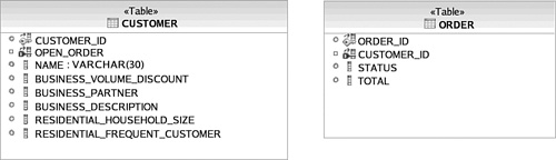
As shown in Figure 3.15, CUSTOMER has a foreign key constraint associated with ORDER and vice versa. It is clear that CUSTOMER and ORDER have a relationship; however, a lot of information is lost. Modeling the direction of associations is problematic in the database schema when it comes to 1:N cardinality. Shown earlier in Figure 3.3, the domain model, the association labeled as “all” is 1:N and bidirectional. However, in the relational model there is no way to model a field on the CUSTOMER that represents a collection of ORDER data. Instead, ORDER has a foreign key field pointing to CUSTOMER. Starting from the CUSTOMER entity and no prior knowledge, there is no way to determine this relationship.
In fact, the association in a relational schema is not completely modeled by just the foreign key constraint—the joins that traverse these foreign keys are needed to define the association. Thus, the static model is not the complete abstraction. The semantics of the database are defined by the structure and the queries (which has some unpleasant implications on encapsulation and thus protection of the semantics is not possible, which is a later topic).
In a database schema, bidirectional 1:N associations cannot be modeled. Only directional cardinality is possible where the entity with the “1” side of the cardinality has a foreign key for the entity corresponding to the “N” side of the cardinality.
This impedance mismatch also occurs if the domain model contains a 1:N directional association where the association is initiated from the single side to the many side of the cardinality.
Our domain model includes such an association between Order and LineItem, as shown in Figure 3.16. Only the Order should have knowledge of this association because the association originates from its side. However, in the relational model an ORDER_ID foreign key field must be contained in LINE_ITEM. It is as if the direction of the relationship is in the exact opposite direction in the relational model.
Key Point
Bidirectional and unidirectional 1:N associations are explicitly modeled in an object-oriented domain model, but are implicitly modeled as unidirectional relationships in the relational model originating from the “N” side of the cardinality. [Fowler] refers to this approach of linking the two models together using the Foreign Key Mapping pattern.
Notice in Figure 3.17 how the ORDER contains no information suggesting that there is a relationship with LINE_ITEM. The Order object in the domain model on the other hand has a reference to a Collection of LineItem objects. The ramification of this mismatch in relationship modeling is significant. Because a relational model can explicitly model only a particular kind of unidirectional relationship, mapping to associations cannot be done automatically. This makes creation of a domain model from a database schema difficult. Metadata, often in the form of comments, must be provided by a developer or database administrator identifying which 1:N relationships are bidirectional and which unidirectional relationships initiate from the “N” side of the cardinality.
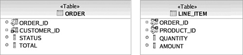
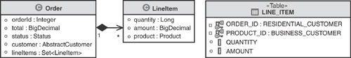
Many-to-many (M:N ) relationships are modeled differently, as well. This stems from the fact that a relational entity is “flat” and cannot really contain a collection, such as the Set<LineItem> on Order in the domain model. Instead, an M:N relationship requires modeling a third entity, often referred to as a join table (also known as an associative table), to hold the foreign keys to the related entities. Sometimes, these join tables can be derived naturally from domain objects. For example, the LINE_ITEM in Figure 3.17 can be considered as a join table that relates ORDER and PRODUCT in a many-to-many fashion. The LINE_ITEM table becomes a convenient place to maintain any attributes unique to the relationship like QUANTITY and AMOUNT.
In many cases, however, there are no attributes associated with the relationship in the domain, so a third table needs to be explicity created during the mapping exercise. Although we did not include such an example in our domain, it is easy to imagine a case where one would be needed.
For example, assume a product can belong to different categories, while a category groups many products. Where the domain model would simply show a many-to-many relationship between Category and Product, the relational model would need to include a third table representing the association. The E-R diagram for this is shown in Figure 3.18.
[Fowler] refers to this approach as the Association Table Mapping pattern. The implicit assumption is that a three-way database join is needed to retrieve both ends of the M:N association from the join table. Navigating this relationship is therefore more costly than 1:1 or 1:N relationships, which need to perform only a single join. When and if this three-way join is performed during processing of a service operation is a significant performance consideration for ORM frameworks and is covered in more detail in the “Object Navigation” section.
M:N associations are not the only associations that require multiple-table joins; in fact, when an object in the domain model is fully populated with its data (when all its attributes are accessed by an application), a join must be performed across all associations. Again, this can have significant performance implications. Thus, when possible, refactor the domain model such that each object has associations to the least number of distinct objects. Multiple associations between the same objects do not require additional joins such as the two associations between Customer and Order.
One way to minimize associations is to create a separate domain model for each state in the lifecycle of an object, such as shown previously in Figure 3.12, which models the lifecycle of an Order.
As we’ve already discussed during the description of the customer order domain model, composition and aggregation are more specific associations. They share all the mapping considerations of a generic association. However, a composition association implies that the associated object is to be discarded should the owner of the association be removed. In Figure 3.19, if the Order is discarded, the LineItem should be as well.
This distinction is of little concern when using object-oriented languages such as Java because objects are removed from memory when there is no longer a reference to them. However, this is not the default behavior for relational databases. The database administrator often has to explicitly instruct the database to cascade the deletion of database rows across foreign key constraints. In some cases, such as in a 1:1 relationship, this is as easy as appending DELETE CASCADE to a foreign key DDL statement.
Unfortunately, using a cascade delete statement is not always possible. This is the case for the 1:N relationship between ORDER and LINE_ITEM shown earlier in Figure 3.17. The ORDER table has no foreign key for LINE_ITEM because of the restrictions on modeling the direction of associations that we already discussed. Instead, the composition must be enforced with a database trigger, such as the Apache Derby trigger shown in Listing 3.5.
Listing 3.5 instructs the database to delete every LINE_ITEM associated with an ORDER when that ORDER is deleted.
Containment refers to the object-oriented concept of a data structure especially designed to contain objects. Examples of containers are Collections, Lists, and Sets. Relational databases support only one form of containment, which is containment of database rows within a table. The containment constructs used in object-oriented systems cannot be mapped directly to relational database systems. In fact, in some cases nothing is modeled in the relational model that corresponds to a container in the domain model.
Some containers have a very strong impedance mismatch with the structure of relational data. Collections that do not implement Set are not required to have unique members. For example, Lists with identical members cannot be modeled in a relational database unless a key is generated, which often breaches 3NF if care is not taken.
Suppose that we want to change the Set<Orders> attribute on Customer to List<Orders> (this makes little sense but we have seen stranger domain models). The ORDER table is consequently changed as shown in Figure 3.20.
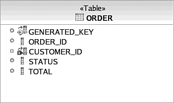
The ORDER table in Figure 3.20 can now persist duplicate Order objects with the same ORDER_ID; however, it is not in 3NF. The fields are not determined solely by the primary key—GENERATED_KEY. They are also determined by the ORDER_ID field. Thus, to achieve normalization, a separate table is needed with GENERATED_KEY and ORDER_ID. This is costly because it introduces a Join to populate the Order domain object.
Encapsulation is the object-oriented concept of reducing the visibility of the implementation for an object in order to provide abstraction to the user of the object. Common encapsulation techniques include utilizing access modifiers (such as private, protected, and public in Java), inheritance, and interfaces. We’ll discuss inheritance and interfaces (as part of the section titled “Polymorphism”) later. Few of these encapsulation techniques can be natively modeled in a relational schema. It should be noted that database views, privileges, and stored procedures can sometimes be useful, but even with these techniques only some object-oriented encapsulation practices can be modeled practically.
In the case of encapsulation, the fact that a relational database does not support access modifiers is not so much a concern as mapping state information from an object that has encapsulated data. If the domain model has an object that encapsulates internal state information with private, packaged, or protected access, it is difficult to persist that state information unless the object already exposes behavior to persist itself (one trick is to use reflection, but this can be restricted by the Java security manager). Often, there is no alternative course of action other than refactoring the domain model in this situation. Thus, a domain model should not include private information at all (of course, the implementation of the domain model may include private data and behavior).
One reason encapsulation is often used in object-oriented systems is to hide information and behavior that should not be reused by other systems or components. Interface constructs are very popular because they expose only needed behavior and hide unnecessary implementation detail. Databases are not well equipped to do this. In fact, it is very common for an application to share a database with various other systems putting it in a position where it has little control of the data. This can painfully limit refactoring capabilities because changing anything in the database is off-limits. It also means great care must be taken if an application caches data from a database.
Inheritance cannot be modeled natively in a relational database. How to map inheritance is not as straightforward as the object-oriented concepts we have surveyed so far. The three commonly used strategies for mapping inheritance are the class table, concrete table, and single table strategies. These are described in the following subsections using the common example’s domain model.
The most intuitive inheritance strategy is to create a table per class, whether it is a superclass or subclass, as shown in Figure 3.21. [Fowler] refers to this as the Class Table Inheritance pattern. Although this makes for a database schema that maps directly to the domain model, it has considerable performance implications. Populating an object in an inheritance hierarchy usually requires a database join to load the subclass and superclass data. For example, to populate a BusinessCustomer object, a join must be done across both the BUSINESS_CUSTOMER table and the ABSTRACT_CUSTOMER table. The join becomes far more expensive as an inheritance hierarchy grows because more subclasses must be included.
Alternatively, the concrete table inheritance strategy represents only concrete subclass objects in the relational schema, as shown in Figure 3.22. A concrete subclass is a subclass that is not labeled as Abstract, and therefore instances can be created by using the class constructor operation (“new”). In this approach, each concrete subclass table has fields corresponding to the concrete subclasses’ fields and those of all of its superclasses in the domain model. [Fowler] refers to this as the Concrete Table Inheritance pattern.
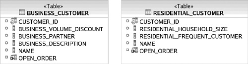
Although this alleviates the Joins required by the class table strategy, it introduces a data integrity problem. We know from our domain model that each customer should have a unique CUSTOMER_ID; however, with this database schema, it is possible to insert the same CUSTOMER_ID in both tables (also there are two NAME columns, and a query for all customers would become two queries—one for each table).
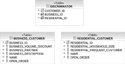
To prevent data corruption of CUSTOMER_ID, either a trigger must be employed for all database write operations to the customer tables or a third table must be introduced, as shown in Figure 3.23. Both options incur significant performance costs. The DISCRIMINATOR table is sparse and thus requires check constraints. As with the class table strategy, the concrete subclass strategy forces the persistence tier designer to compromise on either data integrity or performance.
The final inheritance strategy commonly employed to map object inheritance to a database schema is the single table strategy (which [Fowler] calls the Single Table Inheritance pattern). This is the strategy employed by the common example, as shown in Figure 3.24. As you’ve already seen, this creates a sparse table that requires check constraints to enforce. Sometimes a discriminator field is used to signify which subclass a row represents. It is quite rare to have an inheritance hierarchy map to a single table that is normalized. Thus, flatter inheritance structures are more workable for this strategy.

Polymorphism is an object-oriented concept that allows for different types to expose different behavior through the same mechanism or interface. The most common use of polymorphism is to override a superclass method in a subclass. The application code invoking the method does not need to know which type is used at development time, and thus the method to be invoked is not determined until runtime (often referred to as late binding).
There is no native support for behaviors and polymorphism in relational databases; however, the domain model can exploit polymorphism of attributes as part of inheritance. For example, in Listing 3.6, the binding of the name attribute to the AbstractCustomer reference is considered polymorphic.
Example 3.6. Example using polymorphism with object attributes
AbstractCustomer customer = ...;
if ( java.lang.Math.random() > 0.5 ) {
    customer = new BusinessCustomer("Persistent Enterprises Inc.");
} else {
    customer = new ResidentialCustomer("Eric Harness");
}
Order order = customer.getOpenOrder();
In this example, polymorphism of the getOpenOrder method would allow loading the open order attribute from a different table or column depending on whether the concrete subclass is a BusinessCustomer or a ResidentialCustomer, according to one of the techniques discussed in the previous “Inheritance” section, with the same trade-offs to consider.
The identity of an object is handled quite differently in object-oriented languages in comparison to the identity of rows in a database. Most object-oriented languages uniquely identify the instance of an object according to a memory location. Relational databases identify entities using content—relational calculus comes from set theory and thus two entries are identical if their content is identical. Primary keys are a concept on top of this. They are just the subset of attributes that model (or enforce) identity in the real world. This is fundamentally different from object identity. You already saw an example of this impedance mismatch in the “Containment” section, where we attempted to map a List to a database schema.
Our example domain model also has an object identity mismatch. Notice that the LineItem object in Figure 3.25 does not have an attribute corresponding to ORDER_ID in the database schema. This is implied because the only way to access a LineItem is to use the references in Order’s Set<LineItem>. However, a LineItem with these attributes alone cannot be modeled in the database schema, because the PRODUCT_ID alone cannot be used as a primary key.
This identity mismatch can happen quite frequently because it is natural to minimize the number of attributes on domain objects to keep the model as uncluttered as possible. When one is faced with such a mismatch, there are two fundamental options: either add a unique attribute to the object in the domain model, or create an artificial key on the respective table in the database schema. Most databases have the capability to define a key that is automatically generated using numerical sequences. In the common example schema, we used a combination of the orderId and productId fields to produce a unique key. This approach is discussed in [Fowler] in the Object Identity pattern.
Key Point
When an object in the domain model does not have attributes that uniquely identify the object, an artificial (or surrogate) key column is often required in the database schema.
Even if an object type naturally contains the relational key information from the database, the identity mismatch can cause other problems. For instance, if the same entity is queried twice from the database and populated into two separate object instances, the consequences are severe, including loss of updates, inherent collisions within the same transaction, and the like. These problems can be very difficult to debug in a system at runtime and serve as an excellent example of why object-relational mapping is not trivial.
There is a very strong impedance mismatch between the implementation of object navigation for an object-oriented language and how you navigate to different table rows in a database schema. Navigating a relationship in an object graph in a Java runtime is as simple as accessing a different memory location. Navigating the data in a database schema often requires joins—or even multistep database queries if the relationships are not explicitly represented. In a client/server environment, multiple queries require costly network round-trips. In Java applications, object navigation is cheap and search is costly. Conversely, in a database system navigation is costly and search can be relatively cheap.
Consider the Order to LineItem directional 1:N association in Figure 3.26. When an instance of Order is retrieved from the database, how many LINE_ITEM rows should be retrieved from the database to populate the Set<LineItem>? In-memory object navigation in a Java application accesses the LineItem instances via the references stored in the Set when they are needed individually. But waiting to populate each LineItem from the database with a separate query (called “lazy loading”) may not be a suitable solution to iterate through the Set. An alternative approach is to fetch all possible LineItems—however, this “aggressive loading” may also be impractical because the number of rows may be extremely large compared to the available memory to the application, the database’s processing resources, or the network’s throughput.
In SQL programming, this problem is often solved by retrieving only the LINE_ITEM rows that are needed by the program. For example, perhaps only the LINE_ITEM rows that have an AMOUNT > 100 are needed. This approach is often not possible for the persistence tier of an application because there is usually no way for it to know what members of the Set will be used by the business tier of the application. If it did know, the domain model could be more specific to reflect this additional constraint. In other words, Order would have a greaterLineItems : Set<LineItem> attribute that contains only LineItems with an amount greater than 100.
Key Point
Take care when an object contains collections of other objects. These relationships result in 1:N or M:N relationships in the database, which can have serious performance implications. These relationships should be as constrained as possible to limit the size of the collections that need to be instantiated in the application.
Navigation is therefore at the heart of the impedance mismatch between the object and relational domains. Object-oriented design often tries to factor out any redundancy into separate classes (that is, “One class one concept”—[Gamma]). This approach, using the techniques described in this section, leads to many small classes that get their power from collaboration. In the relational world, this need for factoring is recognized in the concept of normalization, but the cost of navigation is so costly that database design typically leads to fewer and larger tables optimized for the access patterns. ORM frameworks attempt to reconcile these different design goals by using techniques such as caching, paging, and lazy versus aggressive loading; however, these represent trade-offs that are situational, so there isn’t one solution that fits all use cases. In short, it is important to be aware of these trade-offs when constructing persistence models for the object and relational domains.
This section covers the three fundamental approaches to object-relational mapping to try and address these trade-offs in design goals: top-down, bottom-up, and meet-in-the-middle. These approaches center around the flexibility of the relational database and schema used. Most of the organizations we’ve encountered have a legacy database schema in production that cannot be modified because several critical applications still use it. In some cases, data warehousing or federation techniques can be used to, in effect, create a new production schema; however, this increases administration costs and thus total cost of ownership. Thus, for enterprise systems it is most common to see bottom-up and meet-in-the-middle techniques in use. The following sections define these different approaches and the trade-offs they entail.
In a top-down object-relational mapping approach, the domain model dictates the relational schema. That is, the relational schema is optimized for the domain model to minimize the impedance mismatch. This approach often entails generation of a database schema by an ORM framework. Because the schema is generated solely for the domain model and thus a single application, database integrity is often assumed to be enforced at the application level rather than the database level.
Consider Figure 3.27, which shows a possible top-down version of the common example schema. Notice that there are no foreign key constraints. This is handled by the application because it is assumed that no other application will use this database schema. Each table has artificial keys to allow different object instances with the same attributes to be persisted. This removes the necessity to have the ORDER_ID on LINE_ITEM. Although the introduction of the artificial keys breaches 3NF for CUSTOMER, ORDER, and LINE_ITEM, the fact that this database is used only by this application minimizes the ramifications.
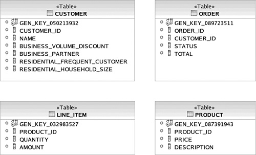
Top-down object-relational mapping is not often seen in enterprise applications that are in production. It is most suitable for applications that use an embedded database (that is, the database is packaged with the code) or in proof of concepts that are testing the functional behavior of the system rather than its performance or maintainability characteristics. In the rare situation where you find yourself building a new enterprise system with top-down schema generation in order to save development time or simplify object-relational mapping, ensure that all stakeholders for the application understand that this oversimplified top-down approach will likely make it impractical for future applications to use the same database schema.
Of course, a more complex mapping that includes primary key columns, foreign keys, and other constraints could be driven “top-down” from the domain model (possibly requiring some additional metadata), so you should carefully look at the top-down mapping features supported by the persistence mechanisms you evaluate.
A bottom-up object-relational mapping approach is the exact opposite of top-down—the domain model is optimized for the database schema. A simple pattern for object-relational mapping that applies to bottom-up mapping is the Active Record pattern [Fowler], in which all tables and domain objects have a 1-to-1 mapping. Bottom-up mapping is also closely related to the Data Access Object (DAO) pattern [Alur], in which each table has a 1-to-1 mapping to DAO transfer objects. The bottom-up approach often involves code generation as well; however, in this case domain model classes are generated from an existing database schema according to a specific set of naming conventions. This of course assumes that the domain model and implementation classes are equivalent, and it severely restricts the use of common object-oriented best practices, such as inheritance and encapsulation.
For example, as you can see in Figure 3.28, a bottom-up domain model leaves us with nothing more than containers for database rows. The objects lose their associations; object navigation is done solely through database queries. It is questionable whether this can be considered a domain model at all. Although this domain may be suitable for a simple “CRUD” application to update database rows, the rest of the application is likely to need a richer domain model that can exploit object features like inheritance and direct navigation through references.
Another key downside to bottom-up mapping is that it forces the use of a domain model that is rarely understandable by the application’s stakeholders. Remember that the primary purpose of a domain model is as a means of communication with subject matter experts and developers alike. The table and column names are rarely user friendly and suitable as a common vocabulary. Furthermore, relational types usually are more restrictive than those associated with the domain. It almost would be better to simply teach all the stakeholders DDL!
Of course, exposing the schema directly to the end users, whether as an object diagram, E-R diagram, or DDL, is considered an anti-pattern in most cases. Exposing the schema prevents you from changes—for example, normalizing or denormalizing the tables to best meet the response time and throughput needs of the application.
Finally, consider that even for simple CRUD applications, there is still an impedance mismatch to overcome when using bottom-up mapping—at least between the database specific “data access” objects and the UI logic of the application. Bridging this gap has just been shifted to the application. Thus, the complexity that was eliminated by optimizing the “domain model” for the database schema arises within other parts of the application.
The meet-in-the-middle object-relational mapping is very much like what you would expect: The domain model is optimized for communication with the stakeholders about the application’s functionality and usability, and the relational model is optimized for the reliability and efficiency with respect to persistence. The common example we explored in this chapter assumed a meet-in-the-middle approach, not only because it is the most common, but also because it illustrates the problems of mapping from either end.
There are good reasons that meet-in-the-middle object-relational mapping is the most common approach used for enterprise systems. Most businesses have used the same database schemas for years, if not decades; and at the same time, a flexible domain model is needed for applications that must be functional, usable, maintainable, and portable. Most experienced database administrators are reluctant to modify a database schema for a single application because it is likely that the schema will outlast the application. We likewise assume a meet-in-the-middle approach for the examples used in the remainder of the book.
This short survey of the mechanics of object-relational mapping has shown how a number of common persistence patterns arise from resolving the object-relational impedance mismatch. There are more patterns, however, that come in handy to map between the objects in an application and the data in a relational database.
Any framework you choose should provide support not only for the three approaches for mapping objects to relational databases and vice-versa, but also for a number of common implementation patterns that impact the maintainability and efficiency of the mapping.
Perhaps the most common pattern used in implementing persistent objects comes about when you specify additional information (often called metadata) about mapping to enable automatic generation (or interpretation) of the logic used to handle the mapping at runtime. This leads to applying the pattern from [Fowler] referred to as Metadata Mapping, and is common in most commercial and open-source OR frameworks.
Another pattern is often applied when you are traversing a number of linked Foreign-Key Mappings, or loading up a large collection of objects from an Association Table Mapping. In this case, you may find that the amount of time and memory needed to “activate” or “deserialize” the objects is quite expensive. Thus, a common optimization in this case is to apply the lazy loading pattern described in the “Object Navigation” section and obtain related objects from the database only when they are referenced. This lazy loading usually is done using an implementation of the Proxy pattern from [Gamma].
Also, when dealing with a relational database, you need to consider the issue of transactionality. Most ORM systems will implement the Unit of Work pattern to gather together database operations that should occur within the context of a single transaction.
The previously described patterns have been a part of ORM systems nearly since their inception. In [Fowler] another set of patterns dealing with distributed systems and “offline” processing was developed that has had an impact on more modern ORM systems, most notably in the evolution of EJBs into JPA. In particular, Fowler discusses how when you are building a distributed system using technologies like CORBA or EJBs, a common approach is to use the Distributed Façade pattern to encapsulate the interactions among a number of domain objects into a single, large-grained interface that is then published externally. The results of that interaction, and the input into a request for a service, is represented as a set of Data Transfer Objects (DTO) that are then mapped into domain objects, usually using the Data Access Object pattern from [Alur], which is a variant of Fowler’s Mapper pattern. The interesting question is whether or not the additional layer of Data Access Objects and Data Transfer Objects is really needed. If a single object can both implement the Data Transfer Object pattern and be a domain object (for example, if a domain object meets all the requirements to be a DTO), then building distributed systems becomes simpler. This approach, in which a persistent domain object can become “disconnected,” is an important design principle and major feature of JPA.
This chapter covered a lot of ground in showing the true complexity of the ORM problem and the demands it will place on a persistence framework. We first discussed the Domain Model pattern and modeling in general as a means for communicating the essential details of a domain, followed by some best practices for modeling that include involving the stakeholders, modeling at the right level of abstraction (or sometimes not creating a domain model at all), and planning for change.
Next we developed a common example that included a domain model and set of associated service operations and unit test cases, as well as a database schema with associated constraints and normalization approach. We used this common example to illustrate the details of the impedance mismatch between the object-oriented world and the relational world, as well as some key patterns for bridging the gap. Some key points that we covered include the following:
Strive to design a domain model with associations and types that are defined as precisely as possible.
Bidirectional and unidirectional 1:N associations from a domain model are implicitly modeled as unidirectional relationships in the relational model originating from the “N” side of the cardinality.
M:N associations are more costly to traverse in a database than 1:N or 1:1 associations, so minimize the number.
A composition association often requires a database trigger to enforce data integrity at the database level.
The class table inheritance strategy works best when the domain model has a relatively flat inheritance hierarchy or when “lazy loading” of super- or subclasses can be employed.
The concrete subclass table inheritance strategy can performantly map a large inheritance hierarchy; however, this performance is often at the cost of relational data integrity.
The single table inheritance strategy works best for flat inheritance structures.
An artificial (or surrogate) key column may be required in the database schema if the associated domain object does not have attributes that uniquely identify the object.
When multiple queries of the same object are performed, the queries should not populate different object instances (unless great care is taken to ensure that these different instances are used in separate transactions).
Take care when an object contains collections of other objects. These relationships result in 1:N or M:N relationships in the database, which can have serious performance implications. These relationships should be as constrained as possible to limit the size of the collections that need to be instantiated in the application.
Then we explored how applying these basic best practice patterns is impacted by which “endpoint” drives the requirements: top-down (the database schema is driven by the domain model), bottom-up (the domain model is driven by the database schema), or meet-in-the-middle (both the domain model and the database schema are fixed).
Finally, we discussed some other important patterns to consider when developing persistence services, such as Metadata Mapping, Lazy Loading, and Unit of Work, as well as Distributed Façades and Data Transfer Objects.
We will use many of these discussion points next in Chapter 4, “Evaluating Your Options,” first to develop a systematic approach to evaluation of the persistence mechanisms, and then apply that approach in the remainder of the book.
An Introduction to Model Driven Architecture | |
The first of a three part series of articles by Alan Brown, this is essential reading to understand the fundamentals of Model Driven Architecture. | |