VoIP, or Enterprise Voice, requires additional configuration and the deployment of new server roles to support this functionality. Enterprise Voice can be easily added to an existing Office Communications Server 2007 R2 IM and Web Conferencing deployment. Enabling Enterprise Voice involves the following activities, which are covered in the next section:
Configuring global Voice settings
Administrating users to be Enterprise Voice–enabled
Deploying media gateways to connect to the PSTN or PBX network
Deploying a Mediation Server for each corresponding media gateway
Optionally deploying one or more Monitoring Servers to collect, aggregate, and report Call Detail Records (CDRs)
Optionally deploying the Deployment Validation Tool to monitor voice quality within and outside the organization’s network
Now that you have a better understanding of the VoIP design of Office Communications Server 2007 R2, this section jumps into the details of configuring VoIP by using the Admin Tools Microsoft Management Console (MMC). The Office Communications Server 2007 R2 Resource Kit also provides useful tools. In particular, the Resource Kit Tool Enterprise Voice Route Helper has several advantages currently not available in the Admin Tools MMC.
Another advantage of Enterprise Voice Route Helper is the ability to simulate the behavior of the system when a particular phone number is dialed. The route taken will be highlighted. Once the administrator is satisfied with her voice configuration, the Route Helper tool can apply the new configuration to Active Directory while maintaining a tracking history of the configurations applied to Active Directory.
The global Enterprise Voice settings can be configured only by administrators who are members of the RTCUniversalGlobalWriteGroup or RTCUniversalServerAdmins groups. Administrator members of RTCUniversalGlobalReadOnlyGroup can view the global settings, but they cannot modify them. The user configures inbound routing rules (simultaneous ringing, call forwarding, and so on).
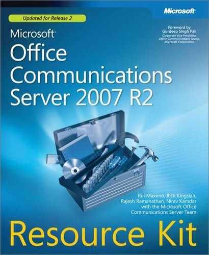
The administrator can create as many Voice policies as desired regardless of whether they are used. To create a Voice policy by using the Admin Tools MMC, select Voice Properties from the forest node and click the Policy tab. The Policy tab enables administrators to manage their Voice policies, as shown in Figure 11-21. Out of the box, a default policy is defined. The administrator can assign all users the same Voice policy or allow users to be assigned a different Voice policy by selecting the Use Per User Policy option from the drop-down list for the Global Policy setting.
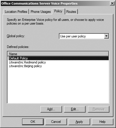
Because Voice policies are associated with phone usages, the administrator also needs to create phone usages to represent routing restrictions. To create a phone usage, navigate to the Phone Usages tab, shown in Figure 11-22. A phone usage consists of a keyword and a description that is used purely for the benefit of the administrator to describe what that phone usage is used for. Out of the box, a default phone usage is defined.
Given the two geographic locations with their own egress to the PSTN in our example, the administrator responsible for this Office Communications Server 2007 R2 deployment defined two Voice policies with associated usages for each office.
A phone route assigns defined sets of phone numbers to various media gateways. Consequently, a phone route consists of a name for the route, a description that the administrator creates, a target set of phone numbers expressed in the form of a regex, a list of gateways to route phone numbers that match the target regex pattern, and a list of usages, as shown in Figure 11-23.

The phone usage ties the phone route to the Voice policy (shown earlier in Figure 11-21). Therefore, only users assigned a Voice policy that specifies the same phone usage associated with a phone route can use that route. The list of gateways is specified by its FQDN and the port number to connect to. This FQDN can be the fully qualified name of an advanced media gateway or the fully qualified name of a Mediation Server if you are using a basic media gateway.
Specifying a target regex can be a little daunting at first when using the Admin Tools MMC. The Enterprise Voice Route Helper tool provides more assistance in defining phone routes. The user interface simplifies the creation of regular expressions. It automatically translates the regular expressions into plain English in the Description field of the route. This makes it easier to understand the meaning of the regex. In addition, the Enterprise Voice Route Helper tool offers the ability to test the regex before saving it.
Figure 11-24 shows the same route defined in Figure 11-18, this time using the Enterprise Voice Route Helper. To view the syntax of the regular expression, click the Raw tab.

Another valuable feature of this tool is the ability to test which route(s) is triggered for a given phone number. This feature is particularly useful because it enables administrators to quickly test phone routes. Administrators can simulate the scenario of a user dialing a phone number and see how the call gets routed without applying the phone route in production (that is, in Active Directory). The route that matches is highlighted. The tool even simulates the phone number normalization performed by the client when the user’s location profile is specified. This feature is available on the Ad-hoc Test tab.
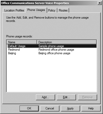
A location profile is a container that holds a name, a description, and a list of normalization rules. Future versions of Office Communications Server will extend the location profile to include additional attributes. Each normalization rule consists of two regular expressions. The first regex is the matching pattern; the second regex is the translation expression. To manage your location profiles, open the Voice properties at the Active Directory forest node and select the Location Profiles tab, shown in Figure 11-25. Embedded within this tab is the UI to create/edit normalization rules.
Note
In the Add Location Profile option, Office Communications Server 2007 R2 provides an Optimize Device Dialing check box. This check box enables the administrator to add an external access prefix of up to four characters (chosen from #, *, and 0–9) that Office Communicator Phone Edition R2 can use to access the outside line.
The Enterprise Voice Route Helper provides a slightly different user interface, with additional features such as assistance in creating regular expressions, seeing which normalization rules are matched as the user types a phone number, and automatically creating or updating the description of the normalization rule.
A default location profile can be assigned to pools. (See Figure 11-26.) Users inherit the location profile of their home pool if the administrator hasn’t assigned a specific location profile to the user. Office Communicator 2007 R2 and Office Communicator Phone Edition 2007 R2 download the location profile from in-band provisioning.

In addition, each Mediation Server is assigned a location profile, as shown in Figure 11-27, because an incoming call from the PSTN might list a phone number that is ambiguous to Office Communications Server. The location profile assigned to the Mediation Server is used to help disambiguate the target phone number.

Configuring users for Unified Communications (UC) is quite simple. Before a user or group of users can be configured for Enterprise Voice, they must be enabled for Office Communications Server and assigned a SIP URI and a home pool. A different license agreement than the standard IM or Web Conferencing Client Access license (CAL) is required before enabling users for Enterprise Voice. The CALs should not be confused with the Office Communications Server SKUs, which come in two offerings: Standard Edition and Enterprise Edition.
To configure a single user for Enterprise Voice, select the user’s Properties from the right-click menu in DSA.MSC or the Admin Tools MMC. On the Communications tab, select the Configure button to view additional options. In the Telephony section, select the Enable Enterprise Voice Routing option and configure the user’s phone number. The option to change the policy selection becomes available so that administrators can specify a different Voice policy. Every Enterprise Voice user must be assigned a Voice policy. This phone number is specified in a valid TEL URI format that is globally unique, meaning no other person has the same phone number extension within the organization. This number is entered in the Line URI field by using the format tel:<phone>. These settings are shown in Figure 11-28.

If an incorrect format is entered, an error warning is displayed. To specify an extension in addition to the phone number, use the following format: tel:<phone>;ext=<extension>. The phone number specified in the Line URI field uniquely associates the user’s SIP URI to this TEL URI. This association enables Office Communications Servers to translate between the two URI formats.
By default, the Policy drop-down option is disabled. The global Voice policy is set to the out-of-the-box default policy. To be able to modify the policy assigned to the user, the Global Policy setting must be changed. To access this global policy, navigate to the forest-level Voice Properties in the Admin Tools MMC and click the Policy tab. Click the Global Policy drop-down list and choose Use Per User Policy. This is illustrated in Figure 11-29. Once the global Voice policy is modified, the user’s Voice policy can be changed and viewed. When the View button is selected, the phone usage associated with the policy is shown.

To configure multiple users at once, a better option is to use the Configure Communications Server Users Wizard. To bulk-configure, select all the users to enable for Enterprise Voice from DSA.MSC or Admin Tools MMC and choose this wizard from the right-click menu, as shown in Figure 11-30.

Because this wizard enables the configuring of all user settings, click Next to arrive at the Enterprise Voice settings. The Enterprise Voice settings to configure are shown in Figure 11-31. The top-level check box, Change Enterprise Voice Settings, must be selected to enable users for Enterprise Voice. The top-level check box indicates that you want to configure the embedded settings. To enable users for Enterprise Voice, the Enable Voice check box must be selected. The policy drop-down list becomes available if the global policy permits it. (See Figure 11-29.) To bulk-disable users, select the Change Enterprise Voice Settings check box and leave the Enable Voice check box unselected. This combination of settings effectively prevents users from using Enterprise Voice. Click Next and finally Finish to complete the wizard. The final page of the wizard displays the results of the operation performed. If the wizard indicates that the operation failed for some or all of the users, check whether these users are enabled for Office Communications Server and are assigned a SIP URI and a home pool.

One important point to keep in mind about using the Configure Office Communications Server Users Wizard is although users might be enabled for Enterprise Voice, unless these users were previously provisioned with a TEL URI that remains unique, they will not be reachable via a phone number if the Line URI field remains blank. The Configure Office Communications Server Users Wizard does not configure the Line URI field because each user must have a unique TEL URI. To bulk-configure the Line URI field, you need to resort to using the following Office Communications Server WMI interface: MSFT_SIPESUserSetting.LineURI.
The media gateway is a third-party server role offered by Microsoft’s partners that is used to convert the signaling portion, SS7, of the PSTN traffic into SIP and the media portion of the PSTN traffic into RTP. Because each media gateway vendor will likely expose its management settings differently, this book will not cover the step-by-step procedure necessary to configure all the settings of the media gateway. Instead, the administrator should refer to the media gateway vendor’s documentation, which is often available online.
Microsoft differentiates media gateway vendors into three categories that it supports. The first category, referred to as basic media gateways, requires the deployment of Office Communications Server Mediation Server to work with Office Communications Server 2007 R2. Depending on the vendor, installing its media gateway service on the same physical server colocated with the Mediation Server service might be supported. Nevertheless, from a logical perspective, they are considered separate servers. The second category, referred to as advanced media gateways, does not require deploying Mediation Servers to interface with Office Communications Server 2007 R2. The third category, referred to as hybrid media gateways, consists of a basic media gateway with the functionality of the Mediation Server coexisting on the same physical server. More details are covered in the section titled "Bridging VoIP to the PSTN Network by Using a Media Gateway" in Chapter 4.
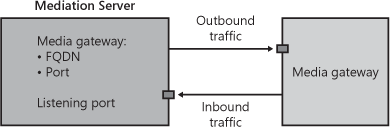
The media gateway must be configured with the Primary Rate Interface/Basic Rate Interface (PRI/BRI) lines allocated by your telecom provider, which connect it to the PSTN network. On the network interface card (NIC) connected to the internal IP network, the gateway should be configured to connect to the Mediation Server if you are using a basic media gateway. To configure the media gateway to send and receive traffic from the Mediation Server, the following settings must be configured:
Inbound traffic. A listening port on the media gateway must be configured to listen for incoming traffic from the Mediation Server.
Outbound traffic. The media gateway must be configured with the FQDN or IP address of the Mediation Server and the port number it will send outbound traffic to.
This configuration is illustrated in Figure 11-32.
The Mediation Server is a server role that is required if you are using a basic media gateway to function with Office Communications Server 2007 R2. Because the majority of basic media gateways support only SIP over Transmission Control Protocol (TCP) or UDP, the Mediation Server extends the security of the Office Communications Server system up to the basic media gateways by translating SIP over TCP/UDP to SIP over mutual transport layer security (MTLS). This is why it is recommended that you deploy a Mediation Server within proximity to its associated media gateway. To prevent internal users from eavesdropping on phone conversations, the network connection between the Mediation Server and media gateway should be placed on a separate network inaccessible to the users. Microsoft’s objective is to help media gateway third-party vendors integrate as much of the Mediation Server functionality into the media gateway servers, referred to as advanced media gateways. The objective is to remove the Mediation Server role entirely. This will help reduce the added complexity that deploying and managing another server running the Mediation Server role creates, and consequently it will likely reduce total cost of ownership (TCO). Until third-party media gateway vendors are able to integrate this functionality into their offerings, a Mediation Server is required. The Mediation Server provides the following functions:
Intermediate signaling (SIP) between Office Communications Servers and the media gateway.
Transcodes RTP media traffic from legacy codecs—such as G.711, G.722.1/SIREN, G.723.1, G.726, and GSM—that are used by media gateways to the Office Communications Server 2007 R2 advanced audio codec, Real-Time Audio (RTAudio). Note that G.729 is not supported by Office Communications Server.
Acts as an Interactive Connectivity Establishment (ICE) client to enable PSTN-originated media flows to traverse intervening Network Address Translations (NATs) and firewalls.
Provides management, provisioning, and monitoring for the media gateway to integrate into Office Communications Server’s infrastructure of Active Directory, WMI, and MMC.
The Mediation Server installation can be found under the Deploy Other Server Roles option in Office Communications Server 2007 R2 Setup. This is illustrated in Figure 11-33. Office Communications Server 2007 R2 Setup provides a step-by-step set of wizards for installing your Mediation Server.


From a configuration perspective, a one-to-one correspondence between Mediation Server and the media gateway is required. That is, one Mediation Server is required for each media gateway deployed. The Mediation Server role must run on a computer that is domain-joined to the Active Directory forest where the Office Communications Server 2007 R2 infrastructure is deployed. The Mediation Server must be configured to connect to an Office Communications Server. If a Director is deployed, the Mediation Server can be configured to route calls to the Director; otherwise, the Mediation Server should be configured to route traffic to the home pool closest to it.
Because the Mediation Server is the only Office Communications Server role that connects directly to a basic media gateway, it must be configured to send and receive network traffic to and from the media gateway. The Mediation Server must have at least two NICs configured on the physical computer—one NIC is used for sending and receiving signaling (SIP protocol) traffic from Office Communications Servers as well as audio (RTAudio codec) traffic from internal phone clients, and the other NIC is for sending and receiving signaling (SIP protocol) and audio (G.711 codec) traffic from the media gateway. This is illustrated in Figure 11-34.

Figure 11-34. Internal call routing. Note that the lines connecting the different server roles represent protocol traffic and do not necessarily represent the number of NICs the server must be configured with.
To allow remote users (users connecting from the Internet) who are Enterprise Voice–enabled to dial and receive calls from outside the enterprise’s network, the administrator must specify the A/V Edge Server that the Mediation Server should connect to for both inbound and outbound calls. For security reasons, the A/V Edge Server does not initiate connections to servers in the corporate internal network. When a remote user dials a phone number, the signaling (SIP) traffic to initiate the call traverses the Access Edge Server to the Director, which routes the request to the user’s home pool. The home pool sends the request to the Mediation Server. The Mediation Server forwards the request out to the PSTN through the media gateway. When the call is answered, the Mediation Server needs to establish a connection with the client to obtain the audio media of the call. Using the ICE protocol, the Mediation Server specifies the address of the A/V Edge Server the client should connect to through the signaling channel, and on its end establishes a connection to the A/V Edge Server. The address of the A/V Edge Server is the one the administrator configured the Mediation Server with. Once the client and the Mediation Server set up a tunnel across the A/V Edge Server, audio can flow through. The Mediation Server forwards this audio to the media gateway. A similar process occurs when the remote user receives a call. This is illustrated in Figure 11-35.
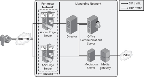
Figure 11-35. External call routing. Note that the lines connecting the different server roles represent protocol traffic and do not necessarily represent the number of NICs the server must be configured with.
Figure 11-36 shows, from the perspective of the Mediation Server, what configuration is necessary to make it work with the other server roles.

The following are descriptions of the numbers keyed to Figure 11-36:
Outbound traffic to media gateway. The Mediation Server must be configured with the IP address of the media gateway and port number it will send outbound traffic to. It receives this information from the Office Communications Server or A/V Edge Server.
Inbound traffic from media gateway. This is the IP address on the Mediation Server that will be used to listen for inbound traffic from the media gateway.
Outbound traffic to Office Communications Server. The Mediation Server is configured with the FQDN and port number of an Office Communications Server to which it will send outbound traffic it receives from the media gateway.
Inbound traffic from Office Communications Server. This is the IP address on the Mediation Server that will be used to listen for inbound traffic from the Office Communications Server.
Inbound/outbound traffic to A/V Edge Server. The Mediation Server is configured with the FQDN and A/V Authentication port number of the A/V Edge Server. The Mediation Server should be configured with a local A/V Edge Server to enable remote users to dial out to the PSTN as well as receive calls originating from outside the user’s organization.
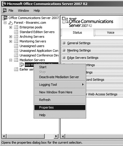
To configure the Mediation Server, the administrator must use the Admin Tools MMC. After installing the Mediation Server, open the Admin Tools MMC and locate your Mediation Server by its FQDN. Right-click your Mediation Server and select Properties, as shown in Figure 11-37.
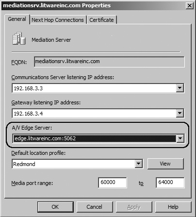
The six settings to configure the Mediation Server so that it can route traffic between the Office Communications Server and A/V Edge Server to the media gateway are split between two tabs. These settings are shown in Figure 11-38, and they are numbered to match the logical representation of these settings, which was shown in Figure 11-36. The first tab, the General tab, is used to specify the IP addresses that the Mediation Server listens on for inbound connections (numbered item 4 in Figure 11-38). In addition, the administrator can specify a location profile for the Mediation Server (numbered item 6). The range of media ports used by the Mediation Server is configurable; however, in most cases the default values do not need to be modified. The second tab, Next Hop Connections, is where the administrator specifies the outbound connections to the Office Communications Server (numbered item 3) and media gateway (numbered item 1 in Figure 11-38).

Before the Mediation Server can establish network connections with other Office Communications Servers it interacts with, it must be configured with a server certificate issued by a certificate authority (CA) that is trusted by the other Office Communications Servers. This configuration can be completed from the Certificate tab.
Returning to the configuration of an A/V Edge Server connection in the Mediation Server properties, if the A/V Edge Server drop-down option (shown as numbered item 5 in Figure 11-38) is empty, this is because no trusted A/V Edge Servers were configured in the Office Communications Server’s global settings at the Active Directory forest level. Once an A/V Edge Server is specified, it becomes visible in the drop-down list of the General tab of the Mediation Server’s properties. To configure your A/V Edge Server, navigate to the Global Properties of the forest node in the Admin Tools MMC and select the Edge Servers tab, shown in Figure 11-39. Click the Add button to specify an A/V Edge Server. The dialog box will prompt you for the FQDN and authentication port number of the A/V Edge Server.

To determine the FQDN and A/V authentication port number of the A/V Edge Server, navigate to the Admin Tools MMC of your A/V Edge Server. The way to get to the Admin Tools MMC of Edge Servers is to right-click My Computer and select Manage, as shown in Figure 11-40.

Expand the Services And Applications node to reach the Microsoft Office Communications Server 2007 R2 node. Click the plus sign (+) next to Internal Interface Settings in the Status pane to expand it. The information to configure the global Edge Server settings is displayed in the Status pane, as shown in Figure 11-41.

Once the A/V Edge Server is specified in the global settings, the A/V Edge Server’s FQDN and authentication port number are visible on the General tab of the Mediation Server, as shown in Figure 11-42.
Configuring the Mediation Server to connect is nearly complete. The Mediation Server is now configured to connect to the A/V Edge Server; however, the A/V Edge Server is not configured to trust incoming network connections from the Mediation Server. To specify the A/V Edge Server to trust the Mediation Server, the administrator must return to the Admin Tools MMC of the A/V Edge Server, select Properties, and navigate to the Internal tab. To add the Mediation Server as an internal server authorized to connect to the A/V Edge Server, click the Add Server button and specify the FQDN of your Mediation Server, as shown in Figure 11-43.

Your configuration of the Mediation Server now enables remote users to place and receive calls when signing in from the Internet.