Dual forking takes its name from the concept of forking; an incoming call is routed simultaneously to multiple destinations. The dual in this term refers to the fact that for each incoming call, both Office Communications Server and the PBX fork the call not only to their own endpoints but also send the call to each other. This is shown in Figure 10-5.
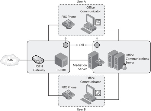
In Figure 10-5, two users—user A and user B—are configured for dual forking. Each user has a PBX phone and Office Communicator. When user A calls user B, the call is "forked" to both the PBX and Office Communications Server systems. User B’s PBX phone as well as his Office Communicator ring. User B has the option to answer the call from either device. This capability is particularly useful if user B is roaming outside the enterprise. In this case, user B can answer the call from a laptop computer running Office Communicator without having to set up a VPN connection into the enterprise.
The PBX shown in Figure 10-5 is also an interface to the Public Switched Telephone Network (PSTN) because that is how an existing PBX within an enterprise is likely to be configured. In all likelihood, the PBX is already hooked up to a voice mail system; therefore, Office Communications Server does not need to provide an additional voice mail solution.
Figure 10-6 shows a more detailed example of how the forking occurs when a call originates from the PBX or the PSTN side. In this case, the PBX is the first entity in the chain to receive the call. Because the PBX is configured to dual fork with Office Communications Server, it sends the call to Office Communications Server in addition to ringing the callee’s PBX phone. The PBX in this case acts like an "anchor" for forking the call. The anchor ensures that when the call is answered at any one device, a cancellation notification is sent to the callee’s other ringing devices in both systems.

Figure 10-7 shows another scenario in which the call originates from the Office Communications Server network instead of the PBX network. In this scenario, the call originating from user A’s Office Communicator is forked by Office Communications Server to user B’s Office Communicator endpoints and to the PBX, which then rings user B’s PBX phone. In this case, Office Communications Server acts as the "anchor" and ensures that when the call is answered, all other ringing endpoints receive a cancel notification. User B can receive the call from either device, similar to the previous scenario.
Note
In a dual forking configuration, the Mediation Server must perform the task of interworking the codecs on both ends. This could lead to some impact on quality. For example, Real-Time Audio (RTAudio) is a wideband (16 bit) codec, and when the call is answered on the PBX phone, the Mediation Server must convert to a G-711 (8-bit narrowband) codec, which is a lower-quality codec. Therefore, the audio quality depends on the type of codecs the PBX system natively supports.
So far we have seen how the dual forking scenario enables the user’s Office Communicator and PBX phones to work together as endpoints. Chapter 9 explained how the RCC scenario enables Office Communicator to remotely control calls in the PBX system.
The dual forking scenario can also leverage the RCC functionality to provide a more integrated experience with the PBX. This optional functionality adds the following capabilities to the dual forking deployment:
Presence integration. When the call is answered from the PBX phone, Office Communicator automatically sets the user’s presence to the In a Call state.
Flexibility to answer calls from Communicator. Users can answer calls from Office Communicator and select where the audio is directed—either to the computer or to the PBX phone.
Controlling PBX call forwarding settings from Communicator. Office Communicator uses the call forwarding configuration from the PBX. It also can set call forwarding rules on the PBX directly.
Note
When RCC is enabled with dual forking, the call forwarding settings configured in Office Communications Server can no longer be controlled from Office Communicator.
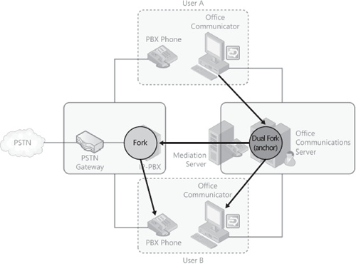
Deploying RCC with dual forking requires deploying and configuring a Session Initiation Protocol (SIP)/CSTA gateway, as described in Chapter 9. Figure 10-8 shows the dual forking topology with the SIP/CSTA gateway added to the configuration.
In this configuration, dual forking with RCC, Office Communicator gets notified twice of incoming calls: once by the SIP/CSTA gateway and again by the Office Communications Server that the PBX signaled to route the call. This is illustrated in Figure 10-9.

If user B answers the call from path 1, RCC is used to answer the call, and the call is terminated on the PBX phone. If user B answers the call from path 2, dual forking is used to answer the call, and the call is terminated on Office Communicator.
Because dual forking requires sending calls from Office Communications Server to the PBX, and in the reverse, calls could potentially bounce from one system to another. Office Communications Server provides the following mechanisms to prevent looped calls:
Office Communications Server does not fork calls that it receives from the PBX back to the PBX.
Office Communications Server inserts a proprietary SIP header, named ms-call-source, in every INVITE message that is forked to the PBX. The ms-call-source header notifies the PBX that it should suppress forking of the call back to Office Communications Server.
Office Communicator 2007 clients have built-in logic to reject a suspected loop call from the PBX. They specifically check for whether a new call is coming in when an existing call is ringing and what the source header in those calls specifies. This loop detection mechanism serves as a fail-safe mechanism for situations in which a PBX does not support loop detection logic that is based on the ms-call-source header mentioned in the previous bullet point.
A PBX without the logic to suppress forking based on the ms-call-source header is shown in Figure 10-10, which illustrates the loop detection mechanism and the various points where a loop could occur. In this example, a call originates from user A’s Office Communicator, and the Office Communications Server dual forks the call to the PBX as well as to the callee’s Office Communicator. Both the callee’s PBX phone and Office Communicator ring. The callee selects to answer the call from Office Communicator. The Office Communications Server, which performed the dual forking for the call, also sends out a CANCEL message to the PBX so that the other PBX phones stop ringing.

"1: loop detect" in Figure 10-10 illustrates how the PBX sends the call back to Office Communications Server, which originated the call. Because the PBX does not understand the ms-call-source header, it fails to suppress the loop back. A PBX certified for dual forking support should have suppressed the call at this point.
Next, the call returns to the Office Communications Server, which is unable to prevent the loop because there isn’t a way Office Communications Server can correlate that the incoming call from the PBX is the same call it sent. It appears as a new call originating from the PBX. This is highlighted as "2: loop detect". Had the call originated from the PBX instead of Office Communications Server, then Office Communications Server would not have sent the call back to the PBX from this loop detection point.
Finally, the call reaches user B’s Office Communicator, which detects that this call is originating from the PBX based on ms-call-source header. It declines the duplicate call because there is already another call in the ringing state from the same user. Office Communicator rejects the call with a 605 reason code. This is highlighted as "3: loop detect". This causes Office Communications Server to suppress ringing any other clients the user is signed in to. Office Communications Server then sends back a 480 temporarily available response to the PBX.
Both the Office Communications Server and PBX systems provide separate call forwarding rules. When RCC is not configured with dual forking, these rules can be set independently and could potentially conflict with each other.
To illustrate, suppose user A sets call forwarding to direct calls to user B from Office Communicator. When an incoming call is addressed to user A, Office Communications Server will forward the call to user B per user A’s call forwarding rule. However, the PBX is unaware of this forwarding behavior. The PBX continues to ring user A’s PBX phone, whereas Office Communications Server will ring user B’s Office Communicator. The dual forking design mitigates this erroneous behavior by using an intermediate call progress SIP signal (181 Call Is Forwarded) that alerts the other system that a forwarding is activated. Once such an alerting signal is received, the PBX stops alerting user A’s phone and keeps the call leg with Office Communications Server up.
Note
PBX systems that do not support the intermediate call progress SIP signal will exhibit the undesirable behavior of the two systems ringing different destinations. A PBX certified for dual forking will support the call progress signal specified above.
From the perspective of the end user, most of the Office Communications Server forwarding rules are similar to a pure Enterprise Voice–enabled user (see Chapter 11), with the following exceptions:
Users cannot be added as delegates or team members.
Voice mail options will not be available for forwarding.
When Do Not Disturb is set on Office Communications Server, calls will still ring on the PBX phone instead of being suppressed. Office Communications Server enables calls to ring on the PBX phone because routing the calls to the voice mail system is handled by the PBX system. For Do Not Disturb to work consistently, the dual forking user must manually set the PBX phone to Do Not Disturb as well.
Table 10-1 summarizes the differences in call forwarding behavior between these configurations. The table indicates whether these features can be accessed from Office Communicator. An entry in the table marked Office Communications Server indicates the feature is available and Office Communications Server provides the feature. An entry marked PBX indicates the feature is available in Office Communicator and the PBX provides the feature. Features marked Not Supported cannot be configured for a user in this configuration from Office Communicator. An entry marked Optional indicates the feature can be optionally turned ON.
Table 10-1. Call Forwarding Features in Communicator Forwarding UI
FORWARDING FEATURE | ENTERPRISE VOICE (OFFICE COMMUNICATIONS SERVER, VOIP) | ENTERPRISE VOICE WITH PBX INTEGRATION (DUAL FORKING) | ENTERPRISE VOICE WITH PBX INTEGRATION AND RCC (DUAL FORKING WITH RCC) |
|---|---|---|---|
Call Forwarding Immediate | Office Communications Server | Office Communications Server | PBX |
Call Forwarding Unanswered | Office Communications Server | Office Communications Server | Not Supported |
Ring Duration | Office Communications Server | Office Communications Server | Not Supported |
Simultaneous Ring PSTN Phone | Office Communications Server | Not Supported | Not Supported |
Delegate Configuration | Office Communications Server Delegates use Attendant Console | Not Supported | Not Supported |
Team Call | Office Communications Server | Not Supported | Not Supported |
Forward to Voice Mail | Optional | Not Supported | Not Supported |
Presence-Based Forwarding (Do Not Disturb) | Office Communications Server | Office Communications Server only (PBX phone will ring) | Office Communications Server only (PBX phone will ring) Note: Do Not Disturb integration with RCC is not supported |
Working Hours Only Forwarding | Office Communications Server | Office Communications Server | Not Supported |
Dual forking scenarios leverage calls being routed across Office Communications Server and the PBX by using phone numbers. Office Communications Server forks the call to the PBX addressed to the user’s phone number. Similarly, the PBX system sends the forked call to the Office Communications Server addressed to a phone number. Therefore, for dual forking to work properly, phone numbers specified in Active Directory and in the PBX system must be mapped to the same user.
When the user is configured for dual forking, Office Communications Server uses the user’s Line URI attribute defined in Active Directory to route calls to the PBX. The Line URI should contain a phone number defined according to the Request for Comment (RFC) 3966 TEL URI format. The PBX should be able to accept calls destined for the phone number specified in the Line URI and ring the appropriate phone line associated with that Line URI. When sending calls to Office Communications Server, the PBX inserts the destination phone number in the To URI of the SIP request. Office Communications Server matches the phone number in the To URI to the Line URI of the callee and routes the call to the correct user. Therefore, incoming calls from the PBX should have phone numbers in the To URI that match the phone number in Active Directory.
In addition to routing calls to the correct destination, Office Communicator clients use the phone number in the From URI (if properly formatted by the PBX) to perform reverse name lookup and match the phone number to the caller’s Line URI, which provides caller ID information to the callee.
When configuring dual forking with RCC, it is important that phone numbers in the From URI that is being sent in the VoIP INVITE from the PBX match the phone number in the calling party information in the incoming CSTA message. Office Communicator uses the calling party information to suppress the other incoming call notification and provide the redirect option to the alternate device (as seen in Figure 10-2).
The following phone number formats are supported:
E.164, such as +14255551212
E.164 with extension, such as +14255551212;ext=1212
The second format is recommended for PBXs that do not support Direct Inward Dialing (DID) numbers but do have a switchboard number available. In this situation, the number +14255551212 is the switchboard number and ext=1212 is the local extension.
Note
When the user is configured for dual forking with RCC, and there is a mismatch in the From phone numbers between the VoIP INVITE and the RCC call or if the phone number is anonymous, then Office Communicator will not be able to match the two calls to merge the call notification. In this case, the user will see two incoming call notifications for the same call, with one corresponding to the RCC call and one corresponding to the VoIP call.
Phone number normalization in a dual forking scenario uses normalization rules closer to VoIP scenarios (Enterprise Voice) than to RCC. In dual forking, the user must be able to use Office Communicator as a softphone to dial a number, and this requires support for location-based normalization rules. For more details on normalization, see Chapter 11.
Table 10-2 outlines the normalization rules used in different scenarios. Note that Address Book Server (ABS) rules are used for normalizing the phone numbers across the directory, whereas the per-location normalization on the clients depends on the specific configurations.
Table 10-2. Normalization Rules for Office Communications Server 2007 R2
CONFIGURATION | NORMALIZING PHONE NUMBERS IN GLOBAL ACCESS LIST | NORMALIZING USER-DIALED NUMBERS BY CLIENT | ROUTING CALLS BY SERVER |
|---|---|---|---|
Enterprise Voice | ABS rules | Location Profile rules | Location Profile rules |
Enterprise Voice with PBX Integration | ABS rules | Location Profile rules | Location Profile rules (on Office Communications Server only) |
Enterprise Voice with PBX Integration and RCC | ABS rules | Location Profile rules | Location Profile rules (on Office Communications Server only) |
RCC | ABS rules | ABS rules | Not used |