Chapter 3
Modeling and Simulation of Analog Angular Sensors for Manufacturing Purposes 1
This chapter develops a new mathematical model, for pancake resolvers, which depends on a set of variables controlled by the sensor manufacturer — the winding parameters. This model allows a resolver manufacturer to manipulate in-process controllable variables in order to readjust already assembled resolvers that without any action would be scrap for the production line. The developed model follows a two-step strategy where on a first step a traditional transformer’s model computes the resolver nominal parameters and on a second step a linear model computes the corrections on the controllable variables, in order to compensate for small deviations in design assumptions, caused by the variability of the manufacturing process. At the end of the chapter an experimental methodology for parameter identification and several tests for model validation are presented.
3.1. Introduction
Resolvers are nowadays widely used in industrial applications. These electromagnetic devices which were, in the past, largely used in military applications, namely to control the position stability of heavy guns, are presently very common in industrial areas as a servomotor component. Servomotors are today widely used in robotics, rotary machinery, radars, aeronautics, etc.
The main factors that promote the widespread use of synchros and resolvers as angular sensors are their robustness and stability in non-friendly environments such as mechanical vibrations, shocks, environments with dust, oil, and radiation. Besides, these electromagnetic devices have very stable properties when subjected to extreme temperature variations (−50º C to +150º C) and high rotational velocities (1,000–10,000 rpm).
The wide application fields of synchros and resolvers can be grouped into three main areas [GOL 81]:
– distant transmission of absolute angles — Figure 3.1;
– analog computation of the difference between two angles (reference and actual values) — Figure 3.2;
– servo-systems (where the information signals are apart from the energy signals) — Figure 3.3.
Figure 3.1. Distant transmission of absolute angles

Figure 3.2. Analog computation of the difference between two angles

Figure 3.3. Servo-systems

The main disadvantages of synchros and resolvers in relation to optoelectronic encoders are both the necessity of an AC-power source and the delivery of an analog output signal. However this latter disadvantage is nowadays vanishing due to the advances in signal processing technology that is constantly delivering more speedy and cost-efficient solutions to convert analog to digital signals. The market’s continuous search for more accurate devices and the wide availability of digital controllers coupled to servomotors is increasing today’s demand for resolvers as function systems, able to be connected with analog/digital converters as is shown in Figure 3.4.
Figure 3.4. Resolver as a function system coupled to ADC device

The main research areas focusing resolver development can be grouped into three fields:
– Model development [SUN 08], [BRA 09], [BEN 07], [KIM 09], [HOS 07], [FIG 04], [ALH 04];
– Analog to digital converters [ATT 07], [HAN 90], [VAZ 10], [BRA 08], [SAR 08], [BEN 04], [BEN 05];
– Applications [BUR 08], [BUN 04], [MUR 02], [MAS 00].
This chapter concerns the research field of model development. In this field some authors focus the efforts on improving the model accuracy [SUN 08], [BRA 09], [BEN 07], others concentrate on developing new procedures for modeling and calibration [KIM 09], [HOS 07], [FIG 04].
In [FIG 04] an explicit mathematical model for a pancake resolver is presented. This former paper develops an explicit model for pancake resolvers following the traditional approach from transformer models, where the main parameters are the resistances of primary and secondary coils, the magnetic resistances, and the leakage impedances.
The model developed in [FIG 04] has little use for a resolver manufacturer because it does not give any help supplying a specific path where the manufacturer can act to compensate the deviations in assembled products due to the variability of the manufacturing process.
This chapter enlarges the applicability of the study formerly developed in [FIG 04] by proposing a new mathematical model developed for resolver manufacturers, where the model parameters are the production controllable variables.
The main functional characteristics of a resolver are the angular error, the output voltage (transformer ratio, r), the phase shift, and the input current. All these important factors, specified by applications, are strongly influenced by constructive factors such as magnetic properties of stators and rotors, winding geometries, and manufacturing tolerances of mechanical parts.
Facing this situation, it is clear that the availability of a mathematical model, at the resolver manufacturer, allowing the producer to simulate the characteristics of its products, in the presence of high variability of production factors, is a valuable asset. The availability of a simulation model supplying the resolver production parameters, with high accuracy, implies a smaller number of prototypes needed until customer specifications are effectively met. In the end, this efficiency increase corresponds to a large amount of money that is saved yearly, by the resolver manufacturer, as the number of wasted prototypes is reduced.
The present market for analog angular sensors is extremely competitive as new applications are continuously arriving, encouraging a fall of the prices as a way to reach other markets (the automotive market is today still a marginal market for resolvers but the pressure to expand into this market is extremely high) [MUR 02], [BER 03], [MAP 10].
This chapter develops a new mathematical model for pancake resolvers, dependent on a set of variables controlled by a resolver manufacturer — the winding parameters. The developed model follows a two-step strategy where in a first step a traditional transformer’s model computes the resolver nominal conditions and in a second step a linear model computes the corrections on the controllable variables, in order to compensate for small deviations in design assumptions, caused by the variability of the manufacturing process.
3.2. Pancake resolver model
3.2.1. Description
The pancake resolver is the most popular resolver in industrial applications and aeronautics because its design avoids the traditional collector that brings energy to the rotor.
The pancake resolver carries the current into the rotor through a transformer that is located at the stator edge. The advantage of such a design, over the traditional resolver with collector, is the absence of the relative movement between mechanical parts which causes wear, vibrations, and sound. Figure 3.5 presents the two above-mentioned designs.
Figure 3.5. Traditional resolver (left) and pancake resolver (right)

Independently of how the energy is brought into the resolver rotor, the function of a resolver, as an angular sensor, can be briefly illustrated in Figures 3.6 and 3.7.
Figure 3.6. Resolver function schematics

Figure 3.7. Resolver input and output voltages

As can be seen, the secondary coils, which are geometrically shifted by 90°, deliver two output voltages that are modulated in magnitude according to the cos and sin functions of the relative angular position of rotor to stator.
This physical effect was first developed by Werner Siemens in 1896 [SIE 96]. Today, the currently available resolvers have an average accuracy of ±0.2°. The angular position of the rotor referred to the stator can be obtained as in [3.1]:
r = transformer ratio;
α = relative angle rotor to stator;
U0 = input voltage;
US1S3, US2S4 = output voltage from each stator winding.
3.2.2. Mathematical model
The commonly used mathematical models for resolvers are the typical transformer models that are shown in Figures 3.8, 3.9, and 3.10. These models are very suitable to supply the usual customer electrical characteristics for resolvers, namely the rotor and stator impedances (open and short circuited).
Figure 3.8. Rotor impedance with stator open (Zro) and rotor open (Zso)

Figure 3.9. Rotor impedance with stator shorted (Zrs)
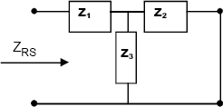
Figure 3.10. Stator impedance with rotor shorted (Zss)
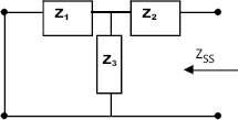
According to the below schematics (Figures 3.8–3.10) using the traditional circuit analysis methods, the following equations are derived:
where,
Zro = rotor impedance with stator open;
Zso = stator impedance with rotor open;
Zrs = rotor impedance with stator shorted;
Zss = stator impedance with rotor shorted.
This traditional, well-known model, although very useful for computing the main electrical characteristics for customers, is of little use to the manufacturers as it cannot deliver data for production purposes. Actually this model does not supply any controllable parameter for the resolver manufacturer (number of windings and wire diameters).
The new model proposed in this chapter is appropriate for resolver manufacturers because it deals explicitly with the actually controllable variables in a resolver production plant — the winding parameters.
The main resolver variables that directly influence the customer-specific electrical characteristics can be grouped into three areas:
Group 1: material-related variables — magnetic permeability of materials (rotor, stator, rotor-transformer, stator-transformer).
Group 2: geometry-related variables — dimensional tolerances of mechanical parts (rotor, stator, rotor/stator air-gap, transformer air-gap).
Group 3: winding-related variables — spatial distribution of windings, number of windings, and winding wire diameters (in all four components: rotor, stator, rotor- transformer, and stator-transformer).
From these three groups of variables, the resolver manufacturer can directly influence only the third group (winding-related variables). In fact, the other two variable groups are usually fixed for the assembly line as the resolver manufacturer usually buys the materials and parts from external suppliers.
In such a scenario a useful mathematical model for a resolver manufacturer must deal explicitly with the controllable variables at the assembly line — winding-related variables (Group 3).
In Figure 3.11 the geometry and function schematics of a pancake resolver are shown. This product is mainly composed by four main coils, identified as A, B, C, and D (A = stator transformer; B = rotor transformer; C = rotor sensor; D = stator sensor).
Figure 3.11. Pancake resolver geometry and schematics

The study developed in this chapter departs from a traditional transformer model [FIG 04] with design variables (ohmic resistors from primary and secondary coils, magnetic resistances and leakage impedances) and updates this model with a sensitivity model that correlates the main electric specifications of a Resolver with the production factors that are controlled by the manufacturer (mainly winding parameters).
The approach developed in this chapter is inspired by the mathematical methodology of a function expansion according to the Taylor series. The strategy adopted here considers the nominal model developed in [FIG 04] to compute the system nominal values — f(x0) — and additionally a linear model, dependent on production controllable parameters, which computes the variable increments. These increments will cancel the deviations on the functional characteristics of the resolver, due to the variability of the production processes in the assembly line. The incremental model that is developed in this chapter is an innovative approach based on experimental parameter identification.
3.2.2.1. Model for nominal conditions — [f(x0)]
Observing the pancake resolver functionality we can consider this device as two standard transformers connected in cascade. The first one supplies the energy into the rotor, with an output voltage that is independent from the relative position of rotor to stator, and the second one, that models the resolver function itself, which can be considered as a rotational transformer with an output voltage that is dependent on the rotor/stator relative angular position.
The model adopted for each one of the above referred transformers is a complete model for a mono-phase transformer, considering magnetic losses in metal and windings. The respective block diagram is presented in Figure 3.12.
Figure 3.12. Complete mono-phase transformer model
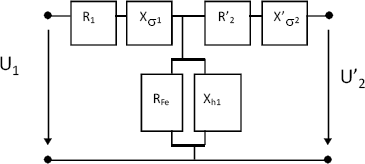
The variables represented in Figure 3.12 account for the following effects:
R1 = primary winding resistance;
R′2 = affected secondary winding resistance (viewed by the primary winding);
RFe = magnetic metal resistance;
Xσ1 = primary winding leakage impedance;
X′σ2 = affected secondary winding leakage impedance (viewed by the primary winding);
Xh1 = impedance related to common flux.
Connecting two of the above transformer models in cascade we get the complete model for our pancake resolver, which is presented in Figure 3.13. The indexes T and D account respectively for transformer and sensor.
Figure 3.13. Complete pancake resolver model
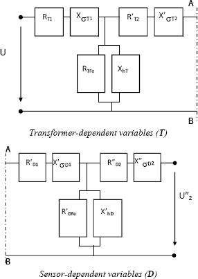
Considering the resolver model described in Figure 3.13, we can simplify this model by combining the impedances (serial and parallel), according to the following schematics.
The simplified impedances are calculated according to the following expressions:
Simplifying the serial association of the Zi and Z0 impedances, we obtain the triangular system of impedances illustrated in Figure 3.15.
Figure 3.15. Pancake resolver model — second step simplification

The simplified impedance Zi0 is calculated according to the expression:
The above model can now be reworked in order to present a star topology, as it is illustrated in Figure 3.16.
Figure 3.16. Pancake resolver model — third step simplification

The simplified impedances (Zx, Zy, and Zz) are calculated according to the following expressions:
After simple manipulations we can reach the pancake resolver simplified model, as it is illustrated in Figure 3.17.
Figure 3.17. Equivalent-impedance pancake resolver model

The simplified impedances (Z1, Z2, and Z3) are calculated according to the following expressions:
These impedances can now be written according to the resolver electrical characteristics, using the former equations [3.6] to [3.11] (see Figure 3.13), which gives:
where:

For industrial applications, beyond the angle measurement accuracy, which was referred to in equation [3.1], the main resolver electrical requirements are:
(i) output voltage from each stator-winding (ucos,usin);
(ii) resolver input current (i).
Considering the representation of dynamic systems according to the transfer function methodology, this chapter computes the resolver mathematical model illustrated in Figure 3.17 and provides the two explicit transfer functions: Ucos(s)/U0(s) and I(s)/U0(s).
To calculate the transfer functions referred to above we started from the resolver model presented in Figure 3.17. This model is then reworked in order to obtain a frequency model, which is explicitly dependent on the frequency input of the supply network (s = jw).
Considering the former model already presented in Figure 3.13, that is equivalent to the following model, illustrated in Figure 3.18, when the below relations are considered:
Considering the resolver model — equations [3.19] to [3.21] (see Figure 3.17) — the system transfer function (U″2(s)/U0(s)) can be directly obtained by using the usual block diagram algebra:
where Z1 and Z3 have already been defined in the former equations [3.19] and [3.21]. Simplifying these impedances now (beginning by the variable ZDen), we obtain, considering the notation from equations [3.22] to [3.27]:
Figure 3.18. Complete pancake resolver model
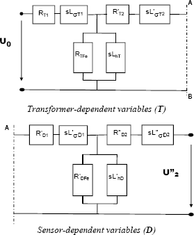
First simplifying the numerator of ZDen (numZDen) we obtain:
After several manipulations, numZDen can be written as:
Rewriting the numZDen in a simplified way, we obtain:
where:
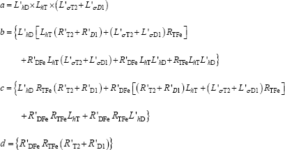
Finally, ZDen can be written in a simplified way:
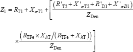
Following the same methodology we can now simplify Z1:
First simplifying the Z1 numerator (numZ1) we obtain:
Finally, Z1 can be written in a simplified way:
Simplifying the last impedance Z3 now we obtain:
Knowing that the relationship between the resolver output voltage Ucos and the voltage U″ is dependent on the device’s global transformer ratio leads to the equation:
where:
rT = transformer ratio from transformer (T);
rD = transformer ratio from sensor (D).
According to this equation we can finally derive the system transfer function (Ucos(s)/U0(s)):
where:

The other important explicit model that will be derived here is the transfer function which relates the resolver current consumption (I) with its input voltage (U0).
Considering the resolver model presented in Figure 3.17 (equations [3.19] — [3.21]), we can directly obtain the system transfer function (I(s)/U0(s)) using the usual block diagram algebra:
where:

This obtained explicit mathematical model is suitable to test the accuracy of the assumed approach. In fact, all the parameters needed can be evaluated experimentally as will be explained in section 3.2.2.3.
The above model will be taken to compute the resolver nominal design variables (the standards for all product variables — f(x0)).
In the next section we will introduce a new differential model to compute the influences on the main functional characteristics of a resolver — output voltage (Ucos, Usin) and input current (I) — caused by small changes in product parameters, due to the variability of the assembly processes.
3.2.2.2. Incremental model — [∂f/∂xi)0(∆xi)]
Having a general function f in Rn [f(x1,x2,…,xn)] this function can be linearized around the point (x10,x20,…,xn0) by cutting its Taylor’s serial development after the first order partial derivatives, which leads to:
This methodology was used to build up a new mathematical model that was able to compute the influences on the resolver main functional characteristics: output voltage (Ucos, Usin) and input current (I) caused by small changes on the manufacturer controllable variables (winding parameters).
The linear model presented here develops a complete new approach to model the product characteristics of a pancake resolver from the knowledge of the manufacturer controllable variables (winding parameters).
In Figure 3.19 the pancake resolver controllable model for a standard manufacturer is shown.
The variables considered by the are:
U0 = resolver input voltage;
F = input frequency;
nst = number of windings of the stator transformer;
nrt = number of windings of the rotor transformer;
nss = number of windings of the stator sensor;
nrs = number of windings of the rotor sensor;
ϕst = winding wire diameter of the stator transformer;
ϕrt = winding wire diameter of the rotor transformer;
ϕss = winding wire diameter of the stator sensor;
ϕrs = winding wire diameter of the rotor sensor.
Figure 3.19. Resolver controllable model

The differential model for the resolver output voltage — Ucos — considers the marginal changes on the manufacturer controllable variables (winding parameters) and it can be computed as it is shown in equation [3.43].
Using the same approach, the influences on the input current — I — caused by small changes on the controllable variables (winding parameters) can be calculated as is illustrated in equation [3.44].
The variables with the subscript 0 refer to the nominal conditions computed by the nominal model, previously described in section — Model for nominal conditions [f(x0)].
The several partial derivatives presented in both equations [3.43] and [3.44] have been experimentally identified, with a set of measuring points, which were fitted by second order polynomials (see next section).
3.2.2.3. Parameter identification
The parameter identification for the model developed in the previous section was performed experimentally at Tyco Electronics — Évora plant, applied to the standard pancake 1—speed resolver, with reference H2109, where nominal specifications are:
Input voltage (U0) = 5 V;
Nominal frequency = 4 kHz;
Max. input current = 50 mA.
3.2.2.3.1. Nominal model
In order to evaluate the nominal model parameters we tested this resolver in both cases: open and short circuited. In the open-circuit case the impedances R and Xσ are much smaller than the parallel impedance RFe//Xh, then the complete model from Figure 3.12 reduces to the model presented in Figure 3.20.
Figure 3.20. Reduced transformer model (open circuit)

In the short-circuit case the model from Figure 3.12 reduces to the model presented in Figure 3.21. These computing approaches were applied to both pancake resolver main components: transformer and sensor.
Figure 3.21. Reduced transformer model (short circuit)

The values measured for both transformer and sensor are presented in Table 3.1.
Using these experimental values together with the standard circuit analysis theory, on both the above models (from Figures 3.20 and 3.21), we identify finally the resolver nominal model parameters, presented in Table 3.2. These computed parameters refer to equations [3.40] and [3.41].
3.2.2.3.2. Incremental model
In order to evaluate the incremental model parameters we need to know all the several partial derivatives calculated at the nominal conditions. Here we face a problem because we do not have these mathematical functions. To solve this problem we identified these partial derivatives by experimental measurements and then numerical approximations by second order polynomials [a + b(x-xm) + c(x-xm)2] were accomplished.
Figure 3.22 shows an example of the previously described methodology applied to the identification of the partial derivative — ∂I/∂nst — (input current elasticity in relation to the number of windings of stator transformer) with all other variables set to the nominal values.
Figure 3.22. Parameter identification in incremental model — function ∂I/∂nst
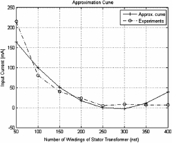
Following the interpolation procedure, we obtain the function:
The procedure described above was applied to identify all the partial derivatives presented in equations [3.43] and [3.44].
3.3. Simulation and experimental results
The results presented in this chapter are split into two groups:
– performance of the overall model (nominal + incremental);
– manufacturer correction tools (incremental model).
3.3.1. Performance of the overall model
The results delivered by the overall model are presented in Figures 3.23 and 3.24. All computations have been done using the Matlab software [MAT].
Figure 3.23. Frequency response results from resolver’s input current magnitude
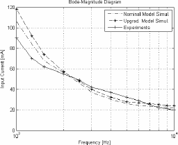
Here we can see the experimental measurements and the simulated values delivered by each model separately — nominal and upgraded models — (upgraded model = nominal model + incremental model).
As was expected, the main contribution is due to the nominal model and the incremental model shows a comparatively reduced contribution although it approximates the simulated values to the measured points.
Figure 3.24. Frequency response results from resolver’s voltage ratio magnitude

3.3.2. Manufacturer correction tools
The results that are shown in this section refer to the incremental model and they were nominated as manufacturer correction tools, as these results are effectively the new developed tools that are available to the resolver manufacturer in order to correct the deviations on product characteristics caused by changes in the production factors (manufacturing processes, materials, etc.).
In fact, a set of correction tools dependent on manufacturer-controlled variables (winding parameters) was developed, and can be used to compensate for deviations in product characteristics.
The knowledge of the developed correction tools permits the resolver manufacturer to change some controllable variables (usually the number of windings in transformers) in order to correct assembled resolvers that without any action would be scrap to the production line (usually input current or output voltage out of specifications).
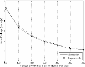
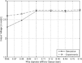
Figures 3.25–3.30 present the simulated and experimental results from some of the developed functions that show the resolver manufacturer the way to act on the correspondent controllable variable in order to influence the resolver main customer characteristics (input current — I, and output voltage — Ucos).
Figure 3.25. Output voltage (Ucos(0)) vs. number of windings of the rotor transformer (nrt)
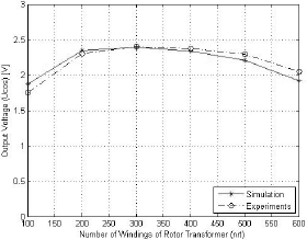
Figure 3.30. Input current (I(0)) vs. number of windings of the rotor transformer (nrt)

3.4. Conclusions
The two-step strategy followed to build up the resolver mathematical model (traditional transformer’s model upgraded with a linear controllable model) proved to be very efficient to the resolver manufacturer.
The newly developed linear model that relates the resolver main electrical characteristics (input current and output voltage) to the manufacturer-controllable variables — basically the winding parameters — allows the development of a set of correction tools that allow the resolver manufacturer to change some controllable variables in order to correct assembled resolvers that without any action would be scrap to the production line.
The denominated correction tools are partial derivatives of the resolver’s main electrical characteristics (input current and output voltage). These partial derivatives reflect the sensitivity of the resolver’s main electrical characteristics to each one of the production controllable variables. This knowledge allows the manufacturer to react quickly to product deviations due to unknown changes in the production processes.
3.5. Acknowledgment
All laboratorial work presented in this chapter was supported by means of manufacturing machinery, test equipment and resolver products by Tyco Electronics — Plant Évora. This work results from an existing cooperation program established between University of Evora and Tyco Electronics — Plant Évora.
The work was supported by Fundação para a Ciência e Tecnologia, through IDMEC under LAETA.
3.6. Bibliography
[ALH 04] ALHAMADI M., BENAMMAR M., BEN-BRAHIM L., “Precise method for linearizing sine and cosine signals in resolvers and quadrature encoders applications”, Proceedings of 30th Annual Conference of IEEE Industrial Electronics Society (IECON 2004), Busan, South Korea, 2–6 November 2004.
[ATT 07] ATTAIANESE C., TOMASSO G., “Position measurement in industrial drives by means of low-cost resolver-to-digital converter”, IEEE Transactions on Instrumentation and Measurement, vol. 56, no. 6, December 2007, pp. 2155–2159.
[BEN 04] BENAMMAR M., BEN-BRAHIM L., ALHAMADI M., “A novel resolver-to-360 degree linearized converter”, IEEE Sensors Journal, vol. 4, 2004, pp. 96–101.
[BEN 05] BENAMMAR M., BEN-BRAHIM L., ALHAMADI M., “A high precision resolver- to-DC converter”, IEEE Transactions on Industrial Electronics, vol. 54, no. 6, December 2005, pp. 2289–2296.
[BEN 07] BENAMMAR M., BEN-BRAHIM L., ALHAMADI M., AL-NAEMI M., “A novel method for estimating the angle from analog co-sinusoidal quadrature signals”, Sensors and Actuators A: Physical, March 2007, Available: http://www.sciencedirect.com.
[BER 03] BERTRAM T., BEKES F., GREUL R., HANKE O., HASS C., HILGERT J., HILLER M., OETTGEN O., REIN P., TORLO M., WARD D., “Modeling and simulation for mechatronic design in automotive systems”, Control Engineering Practice, vol. 11, 2003, pp. 179–190.
[BRA 08] BEN-BRAHIM L., BENAMMAR M., ALHAMADI M., AL-EMADI N., “A new low cost linear resolver converter”, IEEE Sensors Journal, vol. 8, no. 10, October 2008, pp. 1620–1627.
[BRA 09] BEN-BRAHIM L., BENAMMAR M., ALHAMADI M., “A resolver angle estimator based on its excitation signal”, IEEE Transactions on Industrial Electronics, vol. 56, no. 2, February 2009, pp. 574–580.
[BUN 04] BUNTE A., BEINEKE S., “High-performance speed measurement by suppression of systematic resolver and encoder errors”, IEEE Transactions on Industrial Electronics, vol. 51, no. 1, February 2004, pp. 49–53.
[BUR 08] BURROW S., MELLOR P., CHURN P., SAWATA T., HOLME M., “Sensorless operation of a permanent-magnet generator for aircraft”, IEEE Transactions on Industry Applications, vol. 44, no. 1, January 2008, pp. 101–107.
[FIG 04] FIGUEIREDO J., SÁ DA COSTA J., “Analog rotation sensors: an industrial approach for modelling and simulation”, Proceedings of 6th International Conference on Automatic Control, IFAC/APCA, Faro, Portugal, 7–9 June 2004.
[GOL 81] GOLKER W., TAMM H., SMITH S., “Ein messgetriebe fuer den airbus A310: position pick-off unit”, Siemens Components 19, 1981, Heft 4, pp. 125–128.
[HAN 90] HANSELMAN D., “Resolver signal requirements for high accuracy resolver- to-digital conversion”, IEEE Transactions on Industrial Electronics, vol. 37, no. 6, December 1990, pp. 556–561.
[HOS 07] HOSEINNEZHAD R., BAB-HADIASHAR A., HARDING P., “Calibration of resolver sensors in electromechanical braking systems: A modified recursive weighted least-squares approach”, IEEE Transactions on Industrial Electronics, vol. 54, no. 2, April 2007, pp. 1052–1060.
[KIM 09] KIM K., SUNG C., LEE J., “Magnetic shield design between interior permanent magnet synchronous motor and sensor hybrid electric vehicle”, IEEE Transactions on Magnetics, vol. 45, no. 6, 2009, pp. 2835–2838.
[MAP 10] MAPELLI F., TARSITANO D., MAURI M., “Plug-in hybrid electric vehicle: modeling, prototype realization, and inverter losses reduction analysis”, IEEE Transactions on Industrial Electronics, vol. 57, no. 2, February 2010, pp. 598–607.
[MAS 00] MASAKI K., KITAZAWA K., MIMURA H., NIREI M., TSUCHIMICHI K., WAKIWAKA H., YAMADA H., “Magnetic field analysis of a resolver with a skewed and eccentric rotor”, Sensors and Actuators A: Physical, March 2000, Available: http://www.sciencedirect.com.
[MAT] Mathworks, Matlab, The Math Works.
[MUR 02] MURRAY A., HARE B., HIRAO A., “Resolver position sensing system with integrated fault detection for automotive applications”, Proceedings of IEEE Sensors, vol. 2, 2002, pp. 864–869.
[SAR 08] SARMA S., AGRAWAL V., UDUPA S., “Software-based resolver-to-digital conversion using a DSP”, IEEE Transactions on Industrial Electronics, vol. 55, no. 1, January 2008, pp. 371–379.
[SIE 96] SIEMENS E., HALSKE J., Verfahren zur Fernuebertragung von Bewegungen, Patent application no. 93912, Germany, 1896.
[SUN 08] SUN L., “Analysis and improvement on the structure of variable reluctance resolvers”, IEEE Transactions on Magnetics, vol. 44, no. 8, August 2008, pp. 2002–2008.
[VAZ 10] VAZQUEZ N., LOPEZ H., HERNANDEZ C., VAZQUEZ E., OSORIO R., ARAU J., “A different multilevel current-source inverter”, IEEE Transactions on Industrial Electronics, vol. 57, no. 8, August 2010, pp. 2623–2632.
1 Chapter written by João FIGUEIREDO.
