Hierarchical VPLS—Distributed PE Architecture
A hierarchical VPLS (H-VPLS) model allows SPs to interconnect geographically dispersed Ethernet LAN networks. A hierarchical VPLS service is implemented by splitting the physical PE device into many separate physical devices (distributed PE). Therefore, in this architecture, there are two types of PE devices:
User facing PE (u-PE)— CE devices connect to u-PEs directly. A u-PE typically has a single connection to the network PE (n-PE) device placed in the MPLS backbone. The u-PE aggregates the VPLS traffic received from CEs prior to forwarding the same to the n-PE where VPLS forwarding takes place based on the VSI (MAC address learning and switching).
Network PE (n-PE)— u-PEs in an H-VPLS network connect to n-PEs where VPLS information is forwarded based on the VSI. The most common form of implementation uses IEEE 802.1Q encapsulation and tunneling. A double 802.1Q encapsulation, also called Q-in-Q encapsulation, can be implemented to aggregate traffic between u-PE and n-PE. The Q-in-Q trunk, therefore, becomes an access port to a VPLS instance on an n-PE. The network PE devices are connected in a basic VPLS full mesh. For each VPLS service, a single-spoke pseudo wire is set up between the u-PE and n-PE. These pseudo wires get terminated on a virtual bridge instance on the u-PE and the network PE devices. Spoke pseudo wires can be implemented using any L2 tunneling mechanism, such as MPLS (AToM) or Q-in-Q (double tagging with 802.1Q VLAN tags). The network PE devices can function as a hub, with the user PE forming the spokes. The architecture, therefore, evolves itself to form a two-tier H-VPLS network because the VPLS core pseudo wire, formed between the network PE devices, is augmented with access pseudo wires formed between the network PE and u-PE devices.
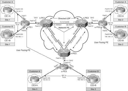
Figure 12-10 shows a H-VPLS network with Q-in-Q tunnels between n-PE and u-PE devices. In this architecture, a full mesh of directed LDP sessions is maintained between n-PE routers. The u-PEs, u-PE1, u-PE2, and u-PE3, connect to the CE devices as well as to the n-PEs.
The spoke pseudo wires are Q-in-Q encapsulated (an 802.1Q VLAN frame encapsulated in another 802.1Q VLAN frame), which allows for customer separation while maintaining customer-specific VLAN information intact. The customer VLAN-tagged traffic is encapsulated in the MPLS backbone with AToM stack and tunneled as Q-in-Q tunnels between u-PE and n-PE.
Figure 12-10 illustrates two customers, Customer A and Customer B, having CE devices located at different sites that are connected to the VPLS provider using Q-in-Q access tunnels. Each customer has its own internal VLANs for workgroup separation. Customer A belongs to VLAN 100 and Customer B to VLAN 200. The objective is to ensure VLAN-to-VLAN connectivity between the different sites belonging to Customer A and Customer B. In the data forwarding and encapsulation process, customers locally generate traffic on each of their workgroup VLANs. The traffic is tagged by customer LAN switches, with appropriate VLAN tags for workgroup isolation, and is sent toward the SP (VLAN tag 100 for Customer A and VLAN tag 200 for Customer B). The u-PE places an additional VLAN tag (VLAN Tag 10) for the traffic originating from the CE device. This traffic is then sent by the u-PE to the network PE, where it is processed according to the VSI for that customer. Outer VLAN tags 100 and 200 are replaced by AToM label stack (LSP label, VC label) and sent across the MPLS backbone.
H-VPLS deployment, therefore, eliminates the need for a full mesh of tunnels as well as a full mesh of pseudo wires per service between all devices participating in the VPLS implementation. It minimizes packet replication and signaling overhead because fewer pseudo wires are required for the VPLS service.
Figure 12-11 shows the data plane forwarding for VPLS architecture using Q-in-Q mode.
Configuration Flowchart for H-VPLS Using Q-in-Q Mode
Refer to Example 12-1 for configuration related to the provider network.
Figure 12-12 shows the steps to configure H-VPLS using Q-in-Q mode.
H-VPLS Configuration Scenario 1—802.1Q Tunneling (Q-in-Q)
The steps to configure the network topology shown in Figure 12-10 are
Step 1. | Configure the Layer 2 interface connected to u-PE device for 802.1Q—In this step, the interface on the n-PE routers connected to the u-PE device for 802.1Q tunneling is configured. This is illustrated in Example 12-20. Example 12-20. Configuring the Layer 2 Interface Connected to u-PE Device
| |
Step 2. | Define the VFI and bind it to the interface connected to the CE—In this step, the VFI is configured. After defining the VFI, you must bind it to one or more attachment circuits (interfaces, subinterfaces, or virtual circuits). The VFI on the n-PE specifies the VPN ID of a VPLS domain, the addresses of other PE routers in this domain, and the type of tunnel signaling and encapsulation (currently, only MPLS encapsulation is supported) mechanism for each peer (shown in Example 12-21). Example 12-21. Define the VFI and Associate It to the Attachment Circuit
|
Verification of VPLS Service
The steps to verify VPLS for the topology shown in Figure 12-10 are as follows:
Step 1. | Ensure that the directed LDP session is operational—Example 12-22 shows the output of show mpls l2transport vc. The output indicates that the AToM VC is functional to transport L2 packets across the MPLS backbone. Example 12-22 shows the output of show mpls l2transport vc on the n-PEs. Example 12-22. show mpls l2transport vc Output on n-PE1, n-PE2, and n-PE3
| ||
Step 2. | Verify data plane forwarding information—Issue the show mpls forwarding-table command on the n-PEs, as shown in Example 12-23. Example 12-23. show mpls forwarding-table Output on n-PE1, n-PE2, and n-PE3
| ||
Step 3. | Verify MPLS bindings, VC type, and pseudo-wire neighbors—Example 12-24 shows the output of show mpls l2transport binding on n-PE1 where the VC type is Ethernet, which is default unless the remote PE supports only VC type 4 (Ethernet VLAN). Example 12-24. show mpls l2transport binding on n-PE1
Example 12-25. Output of show mpls l2transport summary on n-PE1
|
PE Configurations
The configurations for n-PE devices, n-PE1, n-PE2, and n-PE3, are shown in Example 12-26.
Example 12-26. n-PE Configurations
!n-PE1 hostname n-PE1 ! mpls label protocol ldp mpls ldp discovery targeted-hello accept mpls ldp router-id Loopback0 ! l2 vfi QinQ vpn id 10 neighbor 10.10.10.102 encapsulation mpls neighbor 10.10.10.103 encapsulation mpls ! vlan internal allocation policy ascending vlan dot1q tag native ! interface Loopback0 ip address 10.10.10.101 255.255.255.255 ! interface FastEthernet4/12 no ip address switchport switchport access vlan 10 switchport mode dot1q-tunnel ! interface Vlan10 no ip address xconnect vfi QinQ ______________________________________________________________________ !n-PE2 hostname n-PE2 ! mpls label protocol ldp mpls ldp discovery targeted-hello accept mpls ldp router-id Loopback0 ! l2 vfi QinQ vpn id 10 neighbor 10.10.10.101 encapsulation mpls neighbor 10.10.10.103 encapsulation mpls ! vlan internal allocation policy ascending vlan dot1q tag native ! interface Loopback0 ip address 10.10.10.102 255.255.255.255 ! interface FastEthernet4/12 no ip address switchport switchport access vlan 10 switchport mode dot1q-tunnel ! interface Vlan10 no ip address xconnect vfi QinQ ______________________________________________________________________ !n-PE3 hostname n-PE3 ! mpls label protocol ldp mpls ldp discovery targeted-hello accept mpls ldp router-id Loopback0 ! l2 vfi QinQ vpn id 10 neighbor 10.10.10.101 encapsulation mpls neighbor 10.10.10.102 encapsulation mpls ! vlan internal allocation policy ascending vlan dot1q tag native ! interface Loopback0 ip address 10.10.10.103 255.255.255.255 ! interface FastEthernet2/12 no ip address switchport switchport access vlan 10 switchport mode dot1q-tunnel ! interface Vlan10 no ip address xconnect vfi QinQ |
u-PE Configurations
Example 12-27 shows configurations on the u-PE devices, u-PE1, u-PE2, and u-PE3.
Example 12-27. u-PE Configurations
!u-PE1 hostname u-PE1 ! vlan 100,200 ! interface FastEthernet0/1 description connected to CE1-A switchport access vlan 100 switchport trunk encapsulation dot1q switchport mode dot1q-tunnel no cdp enable spanning-tree bpdufilter enable ! interface FastEthernet0/2 description connected to CE1-B switchport access vlan 200 No switchport trunk encapsulation dot1q switchport mode dot1q-tunnel no cdp enable spanning-tree bpdufilter enable ! interface FastEthernet0/12 description connected to n-PE1 no switchport trunk encapsulation dot1q switchport trunk allowed vlan 100,200 switchport mode trunk ______________________________________________________________________ !u-PE2 hostname u-PE2 ! vlan 100,200 ! interface FastEthernet0/1 description connected to CE2-A switchport access vlan 100 No switchport trunk encapsulation dot1q switchport mode dot1q-tunnel no cdp enable spanning-tree bpdufilter enable ! interface FastEthernet0/2 description connected to CE2-B switchport access vlan 200 No switchport trunk encapsulation dot1q switchport mode dot1q-tunnel no cdp enable spanning-tree bpdufilter enable ! interface FastEthernet0/12 description connected to n-PE2 switchport trunk encapsulation dot1q switchport trunk allowed vlan 100,200 switchport mode trunk ______________________________________________________________________ !u-PE3 hostname u-PE3 ! vlan 100,200 ! interface FastEthernet0/1 description connected to CE3-A switchport access vlan 100 No switchport trunk encapsulation dot1q switchport mode dot1q-tunnel no cdp enable spanning-tree bpdufilter enable ! interface FastEthernet0/2 description connected to CE3-B switchport access vlan 200 No switchport trunk encapsulation dot1q switchport mode dot1q-tunnel no cdp enable spanning-tree bpdufilter enable ! interface FastEthernet0/12 description connected to n-PE3 switchport trunk encapsulation dot1q switchport trunk allowed vlan 100,200 switchport mode trunk |
CE Configurations for Customer A and Customer B
The configurations for Customer A and Customer B CE devices are shown in Example 12-28.
Example 12-28. CE Configurations for Customer A and B
!CE1-A hostname CE1-A ! interface FastEthernet0/0.100 encapsulation dot1Q 100 ip address 172.16.1.1 255.255.255.0 ______________________________________________________________________ !CE1-B hostname CE1-B ! interface FastEthernet0/0.200 encapsulation dot1Q 200 ip address 192.168.1.1 255.255.255.0 ______________________________________________________________________ !CE2-A hostname CE2-A ! interface FastEthernet0/0.100 encapsulation dot1Q 100 ip address 172.16.1.1 255.255.255.0 ______________________________________________________________________ !CE2-B hostname CE2-B ! interface FastEthernet0/0.200 encapsulation dot1Q 200 ip address 192.168.1.2 255.255.255.0 ______________________________________________________________________ !CE3-A hostname CE3-A ! interface FastEthernet0/0.100 encapsulation dot1Q 100 ip address 172.16.1.1 255.255.255.0 ______________________________________________________________________ !CE3-B hostname CE3-B ! interface FastEthernet0/0.200 encapsulation dot1Q 200 ip address 192.168.1.3 255.255.255.0 |


