Data Networking with Routers
Until the push of broadband technology in the last several years, the router was the most common hardware used to connect remote sites requiring multiple user support. Routers are known for their Layer 3 routing capability and multiple physical interface support.
This book covers routing with Linux in detail. However, much of the following covers interfaces that can be purchased for both Linux and hardware-based routers.
One of the major advantages of hardware routers over host-based solutions, such as Linux, is their simplicity and dedicated operating system.With a generic operating system, one of the other services can affect the routing functionality. For example the kernel might mistakenly have an unneeded, buggy, IPX stack compiled with the kernel. In addition, there is also the tendency to activate additional services because “the box can do it.”
In addition many hardware routers, like Linux routers, provide security functionality such as packet filtering, network address translation, and additional networking functions such as acting as a frame relay access device in a frame relay network. On the high end, core routers also can process many more packets than a PC mother-board…the router’s back plane is optimized to route packets quickly.
In addition, hardware routers will typically support a wider range of network interfaces, as was covered earlier.
For these reasons, interaction with routers is likely in most environments…at a minimum the Internet access router provided by the ISP is likely to be a hardware router.Therefore we’ll cover some of the more likely facilities used in enterprise networks.
T1 and E1
As covered in the modem section, the T1 is the 1.54Mbps digital facility that is the standard for voice networks. Its proven technology confirmed its effectiveness in customer premises and has become the standard for narrowband digital communications only likely to be offset by the current broadband technologies. HDSL is the natural replacement and is being marketed as the T1 replacement for business connectivity in some markets.
The T1, a 1.544Mbps link, is made of up 24 64kbps channels referred to as DS0s.
Due to the expense of T1s, U.S. telcos offered a fractional T1 service based upon n X DS0s, and it proved itself very popular for Internet connections and networks requiring point-to-point connections. A T1 or fractional T1 is referred to as a leased line or nailed connection because no dialing or signaling must take place—the connection is always on.
The E1 is the European (and other parts of the world) digital facility that operates at 2.048Mbps. It offers 32 channels of DS0s.
To make use of a T1, the two routers communicating must use the same protocol to communicate. Point-to-Point Protocol (PPP) (covered in Chapter 10, “Planning Router Layout and Function”) is a favorite and offers very good interoperability; however, there is some interoperability with HDLC protocol, and if the same types of routers are used, the vendor specific HDLC can be used.
When more than the bandwidth of a T1 or E1 is needed, the next facility available is a DS3, which offers 44.736Mbps. An E3 has 34.368Mbps and is generally not available to customer premises. The expense and exponential increase cannot be justified by most network upgrades; therefore, multiple T1 connections are chosen.
When multiple connections to the same site are used, a protocol that allows the two links to be treated as one must be used. Some routers allow the connections to use load balancing over the connection, which means that each frame that arrives is sent over the connection where the last frame was not sent (as shown in Figure 12.7).
Figure 12.7. Load balancing.

PPP Multilink protocol as defined in RFC 1717 can also be used to combine multiple connections into one logical connection and has the added advantage of increased interoperability likelihood.
Integrated Services Digital Network
ISDN was the first effort to provide digital services to customer premises and the predecessor to ADSL. ISDN provides two interfaces—the basic rate interface (BRI) and the primary rate interface (PRI).
The BRI provides two channels of 64kbps for payload and a signaling channel of 16kbps.The two payload, or bearer channels, are referred to as B channels, and the signaling channel is referred to as the D channel.
The PRI provides 24 channels for T1 (32 for E1). The most popular use of the PRI is private branch exchanges (PBX), or enterprise telephone switches, which provides such features as voice mail and speed dial. PRI is also very popular for remote access services. The BRI interface has enjoyed widespread use in Europe but has not been widely deployed, especially for voice use, in the United States.
ISDN Uses
The BRI does have some interesting applications for data networking, such as dial–on– demand networks, bandwidth on demand, and dial backup.
Because ISDN is digital, the signaling required to connect is, unlike a modem, very quick. This fact, combined with a total bandwidth of 128kbps for the payload provide network designers additional flexibility in network design.
Dial-on-demand networking avoids the use of a leased line and is transparent to the user or application. By connecting two sites with ISDN, one or both B channels can be dialed when traffic is detected for the remote side, and the channels can be torn down after a certain amount of inactivity. ISDN and dial-on-demand networking is popular in areas where fractional T1 services are not available (mostly Europe) or where the costs of the ISDN are cheaper than a fractional T1. Most service providers bill ISDN based upon usage, so the application is limited in many cases.
ISDN can also be used to create additional bandwidth during peak utilization. For example, a router can be configured to bring up a channel after utilization reaches 98% and should bring the channel back down after it goes back below 95%.The “master” channel can be a leased facility or an ISDN channel.
Probably the most popular use of ISDN in North America is dial backup. The router will use an ISDN connection to connect to the remote site when a network failure is determined. The network failure can be determined based upon a loss of signal on the leased line or by a network event, such as a network routing update announcing the route unavailable.
Frame Relay
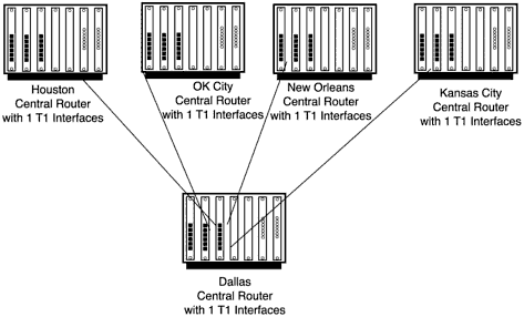
The major disadvantage of leased lines for data communications is the requirement for an interface for each leased line. Consider the network shown in Figure 12.8.There is a central site with four remote sites.With leased lines being used, the central router requires four physical interfaces to be used to network the four remote sites. Additionally, each remote site must route traffic through the central site to communicate with another remote site, or an additional leased line must be activated between the two remote sites.This means that for a 4 node network, 10 connections are required to fully mesh the network.
Figure 12.8. Remote networks with Point-to-Point links.

Because leased lines are very expensive and become more expensive as the distance increases, a network technology that allows a more scaleable architecture is needed for building wide area networks. Frame Relay is such a networking topology.
Frame Relay networks are Layer 2 networks provided by service providers that allow enterprises to build scaleable WANs without requiring a physical interface per connection or leased lines dedicated to individual sites.
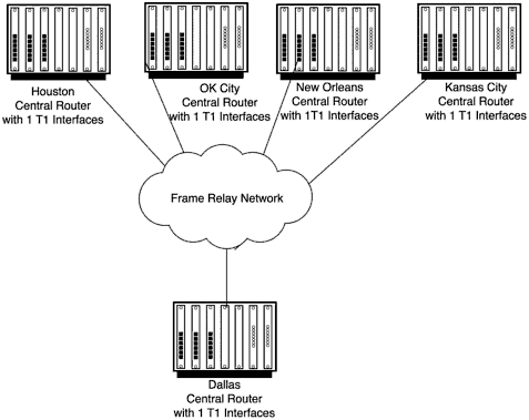
Figure 12.9 shows a typical Frame Relay network as seen by the enterprise customer. It should be noted that the Frame Relay network might or might not provide a complete meshing among the remote sites; typically the customer will have to pay a higher service fee for the full meshing. Should the remote sites not be meshed, traffic will be routed through the central site for Layer 3 routing. Note that the central site in Dallas requires only one T1 interface for connectivity.
Figure 12.9. Typical Frame Relay network.

Figure 12.10 provides a closer look at Frame Relay as seen by the service provider. The Frame Relay switch (FR switch) provides the actual interfaces to the network. Although the Frame Relay network is a private network for the customer, the FR switch is actually a shared resource providing access to many customers in each of the cities where the service provider has a Frame Relay point of presence (POP).
Figure 12.10. Service provider Frame Relay network.

There has not been much Frame Relay development for Linux; however, it is important to know that the technology exists and plays a very important role in many WAN environments. Frame Relay should be considered anytime where multiple site connectivity is needed.
