Open Shortest Path First (OSPF)
The Open Shortest Path First (OSPF) routing protocol is a link-state protocol. This term refers to the reduced amount of information that OSPF keeps track of compared to a protocol such as RIP-2. A link-state protocol uses an entirely different method of choosing routes than a distance-vector protocol.
The Algorithm
Link-state protocols use one of a collection of Shortest Path First (SPF) algorithms. Once again, these algorithms are based on solving graphing problems and then were applied to networking. In the case of OSFP, the algorithm behind the method is the Dijkstra algorithm. Here again, we start with a collection of points. We’ll use the same set shown previously in Figure 1.5.
You must define which points are reachable from which right up front in this case. We don’t start with a theoretical graph where everything can reach everything. You cannot set this data in one direction, either. Some points may only be accessible one way, and others may have a different cost in one direction than in another. So again, let’s use the physical connections laid out in Figure 1.9, adding a new weighting scheme as in Figure 1.14—this time representing both directions of traffic.
Figure 1.14. The example network with bi-directional data paths.

Look back at Table 1.1. The places where data travels over T1,T3, or Integrated Services Digital Network (ISDN) are going to have equal bandwidth traveling in both directions. However, where DSL or 56Kbps modems are used, it might be a different story. Three of the most popular DSL line types consist of two different data pipes and the fourth has four, as shown in Figure 1.15.
Figure 1.15. Data in two types of DSL connections.

The Asynchronous Digital Subscriber Line (ADSL) DSL type has two differently sized pipes for data travel. These bandwidth pipes do not mix. Even if you have completely filled your download bandwidth, it will not start using room allocated for uploading. For the High Density Digital Subscriber Line (HDSL), however, the pipes are equally sized though there are four instead of two. The ISDN Digital Subscriber Line (IDSL) type is a hybrid between ISDN and DSL. While the other DSL types listed here do not keep a connection open on a constant basis (they make the connection when it is needed), IDSL keeps the connection constantly open. This DSL type also has the longest transmission range of the DSLs available today. The fourth popular DSL type is the Synchronous Digital Subscriber Line (SDSL). This line type has equal-sized pipes in both directions.
So, for the sake of making the example network an effective one, let’s say that the DSL item listed in Table 1.1 is ADSL.
The second issue is the 56Kbps modem. Once again, this hardware has different download and upload speeds.You only get 56Kbps for downloads—if you are able to get this speed at all. Uploads are limited to 33.6Kbps in many brands, and while some are able to achieve higher speeds, they typically do not have identical upload and download speeds. The costs to travel from point to point in each direction, taking this information into account, are shown in Figure 1.16.
Figure 1.16. Cost values for our example network using OSPF.

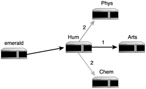
Now that the routers and travel costs are in place, it’s time to actually find the initial best paths. Again, we need a place to start, so let’s use Emerald for consistency. The only place to go from Emerald is Hum, so the algorithm first finds Emerald to Hum, as shown in Figure 1.17.
Figure 1.17. OSPF algorithm in first iteration.

There are three different places you can go from Hum, not counting Emerald (you never travel through the same point twice): Phys, Arts, and Chem. The distances in this direction for each of these are two, one, and two. One is the shortest distance; therefore, the shortest path through these routers, so far, is Emerald to Hum and then to Arts. The paths as they are now are shown in Figure 1.18.
Figure 1.18. OSPF algorithm in second iteration. The heavier line shows the fastest path.

Now we move to the next iteration. This iteration starts at Phys, Arts, and Chem.We cannot pass through a point we’ve already used, so Phys is out of the running for the fastest, shortest path and will not be used in further iterations. However, one key to this algorithm is that we’re not just looking for one path—we’re looking for the fastest way to get from Emerald to everywhere. So, the paths shown in the lighter lines in Figure 1.18 still are useful.
We can still go places from both Arts and Chem. Router Arts reaches to the not yet used nodes of Eng and Math. Chem all of a sudden also has nowhere to go (see Figure 1.19).
Figure 1.19. OSPF algorithm in partial third iteration. The heavier line shows the fastest path up to where it stalls.

Notice that you’re in a dead heat in the costs for going from Arts to Eng and Arts to Math.While this doesn’t affect issues such as where the data’s going, it does cause the problem of determining the central fastest path. This central path is used to determine which router gets the priority as the algorithm goes through its motions. Items on the fastest path get to go through their iterations first, which is why certain points result in dead ends.
How do we then resolve this dead heat? OSPF uses a technique called load balancing to handle such an issue. It literally decides to use both paths alternatively in order to attempt to get the fastest possible data flow. This, however, does not help us with the algorithm itself. To get to the fastest, shortest path and to break the tie, we choose the point with the least number of routers to pass through to get to the rest of the world, which is seven (shown in Figure 1.20).
Figure 1.20. OSPF algorithm with third iteration complete. The heavier line shows the fastest path.

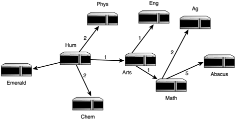
Now that we have this issue handled, we can move to the fourth iteration. The only remaining place to go to from Eng is Ag, and from Math there’s Ag and Abacus. Once again we have to take the fastest central path into account to determine what happens. Because Math is part of the fastest path, we follow that one first. This means that Math leads to both Ag and Abacus, and Eng is another dead end. The algorithm has now finished its job, as shown in Figure 1.21.
Figure 1.21. OSPF algorithm with fourth iteration complete. The heavier lines shows the fastest path. The lighter lines are all paths as well but are dead ends.

How It Works
Now that you understand how the algorithm works, let’s apply OSPF with the same examples used earlier. This protocol is far more complex than RIP-2, so expect this to be a fun ride. Once again, we want to send data from Emerald to Abacus. Emerald knows the following:
What interfaces lead to what routers in its area. An area in OSPF is an independent unit. The example network is a single area in this case. Router three, as it turns out, is the area’s designated router.
A designated router is in charge of talking to the outside world. Within an area, every machine knows how to send data to every address in that area. However, once you get outside of the current area, the routers there see only the designated router and none of the others. As a result, when traffic goes to one of the networks within the area, any router outside sends to the designated router, which then uses its own routing tables to send the traffic to its destination.
If you have an area at all, then you have at least two. Otherwise, there is no need to create one.The sum total of your areas adds up to a full autonomous system (AS). Figure 1.22 shows conceptually how these components all come together. Notice that router Phys has a boundary (and interface) in both of the areas. Remember that the routers have to be able to talk across boundaries! There also will be a router that talks to the outside world from the AS.
Figure 1.22. The example network in its own area, sharing an autonomous system with other areas.

The cost of sending data through each interface. OSPF does not see these costs as any kind of distance measure.They are used simply as a method of weighting which interfaces are going to produce the fastest traffic and which will slow things down.
The shortest paths tree we calculated earlier. Emerald specifically has the tree shown in Figure 1.21. Remember, each machine has its own tree with OSPF.
The cost and path for sending data to the backbone.
Emerald has already used the algorithm we covered earlier to calculate the shortest, fastest paths to all of the other routers. Emerald then knows not only what the next hop will be, but also knows every step of the journey that it would like the data to take. What Emerald does with the data is simply forward it to router Hum, which takes over from there.
Router Hum also has the entire map of the network with costs and both directions. However, it does not use Emerald’s fastest, shortest path calculations. Hum does its own. I’ll leave the algorithm part as an exercise for you, but what Hum comes up with in the end is shown in Figure 1.23.
Figure 1.23. OSPF algorithm results from Hum’s point of view.

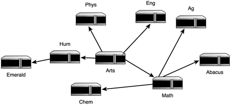
Hum sees Arts as its fastest way to get to Abacus, so it forwards the packet there. Arts then checks its own routing table and fastest, shortest path calculations, as shown in Figure 1.24.
Figure 1.24. OSPF algorithm results from Arts’s point of view.

From Arts, the data goes to Math, and then to Abacus. This time, however, Abacus isn’t on the fastest path. This path gets fairly skewed as each machine builds its own tree.
Now that things are working so nicely, let’s throw the usual wrench in the works. What if our infamous router Arts goes down as it did in the RIP-1 discussion? We’ll use the same three scenarios as we did before to bring home the differences in robustness between RIP-1 and OSPF:
Scenario 1: Router Arts was intentionally removed. It had a critical failure, and there is no backup router available to take its place for a week.
All routers running OSPF regularly—once per HelloInterval setting—make use of the HELLO protocol. This separate communications protocol is used exclusively to connect to the neighbor OSPF routers (those directly connected to the router in question) and to keep that connection going in both directions. The HELLO protocol accomplishes this by using HELLO packets. These special data packets contain introduction information about this router and the costs for traveling through its interfaces, as well as the names of the neighbors of which it is aware.
Arts’s neighbors (Hum, Eng, and Math) are all happily sending out their HELLO packets and receiving them in turn. However, they begin to notice that they are not getting anything from Arts within the set HelloInterval time, which is advertised within the HELLO packets. If they do not hear from Arts within the RouterDeadInterval time after the first missed HELLO packet, the neighbors declare that router unavailable. It won’t be long, then, before all of Arts’s neighbors give up on Arts.
When Hum, Phys, and Math give up on router Arts, they each calculate brand new fastest, shortest path trees with this gaping hole taken into account. No one needs to tell them anything. They can do this all themselves.Thus, where Hum previously had the tree shown in Figure 1.23, it now has the one shown in Figure 1.25. The other two also calculate new trees.
Figure 1.25. Hum’s new path tree when Arts goes down.

As Hum, Phys, and Math send HELLO packets to their neighbors, those neighbors are going to notice the absence of Arts in those packets. They write off Arts as well, and each rebuilds its own tree.
Scenario 2: Router Arts was intentionally removed. It is not going to be replaced with anything else.
While this example was a significantly different issue in the RIP-1 section, it is not here. There is no need for administrators to tell the other routers that Arts is gone. They will all figure this out pretty quickly on their own and build new routing tables, as discussed in Scenario 1.
Scenario 3: The connection Arts uses to access the network went down temporarily, isolating this router, the machines on its own network, and any networks that it is supposed to pass data to from everyone else. This connection stays down for three hours.
At first, this situation behaves as it did in Scenario 1. The fact that there is no router Arts ripples through the network just fine on its own. When the router comes back up, however, you’ll see another big difference in how RIP-1 handled the scenario.
The moment router Arts comes back up, it sends out a broadcast of HELLO packets. All of the neighbors (Phys, Hum, Eng, and Math) get this broadcast and respond to Arts. Then, when these neighbors send out their HELLO packets to others with a list of their neighbors, more of the network sees Arts, and so on. No human intervention necessary.
If you take a glance back at Figure 1.23, you’ll see that this overall system consists of two areas within an AS. This changes the dynamics of the area we’ve been talking about, so let’s discuss that first before we get into the bigger picture. Router Phys is the designated router, also called the border router because it has interfaces in both this area and another. This means that router Phys is considered adjacent, or a neighbor, to every router in the area. Every router sends HELLO packets to Phys, and Phys answers them all. This ensures that Phys always has the big picture of what’s going on in its area.
Now, consider the bigger picture. Figure 1.26 lays out the second area (the dormitories [names abbreviated], which are also networked in the overall campus structure) that router Phys is attached to, and Figure 1.27 shows the fastest, shortest path tree that router East comes up with. First, I need to adjust my vocabulary here. The term router Phys so far has referred to a single machine because you didn’t know it had additional area interfaces. Phys actually refers to the Ethernet card that directly connects to the campus Area. East refers to the Ethernet card that directly connects to the dorm Area.
Figure 1.26. The other area in the AS, where router East is the other interface on router Phys.

Figure 1.27. Router East’s OSPF tree.

The tree for each area is stored separately, and router Phys/East actually runs two copies of the OSPF software for each area. OSPF packets are all marked with an area ID of area they came from, so they don’t leak across a border by accident.
Stepping back even farther, there must be a way available for data to move in and out of the AS. This requires at least one—preferably more than one—AS boundary router. I’ll be a bad network administrator here and add a single AS boundary router to our image, shown in Figure 1.28.
Figure 1.28. The AS complete with its AS boundary router.

This AS boundary router is actually going to receive route advertisements from the outside world as well as send route advertisements to the outside world. These are referred to as external link advertisements. External routing information is shared with all of the routers in the AS with one of two different types of costs:
Type 1. An extension of the path algorithm outside of the AS. Costs for each leg of the path are taken into account exactly.
Type 2. Another type of path extension, except that additional costs are added such that an external path always costs more than any internal path.
The thing to realize is that Phys and East are not designated routers for their Areas because they were somehow born or destined to be designated routers. The HELLO protocol actually elects both a designated and backup designated router. You can stuff the ballot box, though, by giving the specific interface connecting the router to that area a higher priority than the others. If you have two routers connected to the outside world—as you should—then you weight the other one high enough to make it the backup designated router automatically.
Each area in your AS must be internally consistent in its behavior. While I have mentioned some of these values before, a full list of all of the settings that must be identical among all routers in an area—or in the case of an area border router, among all router interfaces in an area—are shown in Table 1.4.
| Setting | Purpose |
|---|---|
| Area ID | The identification value set for the particular area |
| Backup Designated Router | The IP address for the interface leading to the backup designated router |
| Designated Router | The IP address for the interface leading to the designated router |
| Type | The kind of network the interface points to: broadcast, non-broadcast, point-to-point, or virtual link |
Now let’s drill down a bit farther. You also need to be internally consistent for your networks. If you have more than one router attached to a network, which can be a good idea for redundancy reasons, there are certain settings that must be identical for each of the routers attached to that network. The settings I’m talking about here are listed in Table 1.5.
| Setting | Purpose |
|---|---|
| HelloInterval | The number of seconds an OSPF router waits before it sends out its next HELLO packet |
| Network Mask | The netmask for this network, or 0 for an unnumbered point-to-point network or a virtual link |
| RouterDeadInterval | The number of seconds an OSPF router waits since the last HELLO packet before it declares a router dead |
HELLO Packets and Network TypeThe infamous OSPF HELLO packet behaves differently depending on the kind of network you place it on. If you choose a non-broadcast network, then all of the OSPF routers on that network need a list of their neighbors and their ranking in case of a designated router election. On other network types, this is not necessary. |
Drilling down farther still, we get to the OSPF router’s routing table. This table contains:
The IP networks, subnets, and hosts that this destination can forward information to.
The netmask when the destination points to a network or subnet or 0xffffffff if the destination is a host.
The Type of Service (TOS) that should be sent along this route. OSPF is capable of routing data differently depending on its TOS setting.
One of four path types used to send data to this destination: intra-area (within the same area), inter-area (to another area within the same AS), type 1 external, or type 2 external.
The full cost to send data to this destination, as determined by adding the interface costs along the way.
If the path is type 2 external, the routing table also contains the cost for sending the data outside of the AS.
If there are two paths to the same destination with equal costs, the table actually stores the information for both paths in a single entry. In addition to the standard information, there is also the interface to send data out for the next router that can pass the data on to the destination and the IP address of that neighbor. If the destination is in another area or AS, the router ID of the router that data must pass through to get to the destination is included as well.
Finally, the question arises of how all of this data travels between the areas, making the AS a unit unto itself. Just as the Internet is said to have a backbone, an AS has one of its own. The AS backbone consists of area border routers, AS border routers, and networks and routers that don’t exist in an area at all. It is essentially an area of its own, even though it passes through others.
Like a spinal cord, an OSPF AS backbone must be all in one piece to function properly. When two backbone routers are not connected directly by cables, you can connect them using a virtual link in the area border routers.You must create this link in both routers, which will then pretend to have a point-to-point connection between them. The cost for traveling through this connection is the sum of the costs for the real path that the data must take.
As you can see, OSPF is a much more advanced routing protocol than that of the RIP-1 family. It deals with changes in routing structure quickly and efficiently and increases network reliability. The programs used to implement OSPF under Linux are the multi-protocol daemons gated or zebra.
