
Chapter 17: Determining Network Latency Issues
On an enterprise network, it's challenging to manage the everyday demands of keeping the network operational 99.999 percent of the time. The network administrator constantly monitors for issues that can cause a disruption. This situation can be volatile as one error can cause the network to go down. Is there a solution that can help us mitigate this challenge? Fortunately, there is, as Wireshark has several built-in tools that help you troubleshoot the network.
In this chapter, we will address network latency and recognize some of the reasons why packet loss and slow response times occur. You'll gain a better appreciation of the importance of time values while troubleshooting. We'll cover the coloring rules that help identify issues and are used in the Intelligent Scrollbar, so you can quickly identify and move to trouble spots in the capture. Finally, you'll also learn how to navigate the expert information Wireshark generates, which subdivides alerts into categories and guides the analyst through a more targeted evaluation.
This chapter will address all of this by covering the following:
- Analyzing latency issues
- Understanding the coloring rules
- Exploring the Intelligent Scrollbar
- Discovering expert information
Analyzing latency issues
Today, there are many different types of devices that communicate and exchange information across the network, which include intermediary devices, the Internet of Things (IoT), and mobile devices. All of those, along with the many other types of traffic that are added to the network on a daily basis, can make network administration challenging.
Because of these factors, there are multiple reasons why packet loss and slow response times occur. Once it's determined that there is an issue, the troubleshooting process begins.
When troubleshooting connectivity issues, there are many approaches. All have the same goal: identify the trouble spots and narrow the scope to determine the root cause of the problem. Root causes can include misconfiguration, malware, or even hardware malfunction. In the following sections, we will analyze some of the root causes behind network delays and discuss three main concepts: latency, throughput, and packet loss.
Grasping latency, throughput, and packet loss
When users complain of slow response times, the network administrator can do a quick packet capture and observe evidence of trouble. In this section, we will walk through some examples to demonstrate how you can identify issues on the network. If you would like to follow along, go to https://www.cloudshark.org/captures/9a5385b43846, download the client-fast-retrans.pcap capture, and open it in Wireshark.
Once the file is open, we can scroll through the capture. Around packets 20-21, we can see potential problems, as indicated by the black coloring rule seen within the capture:
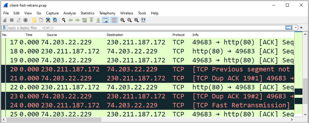
Figure 17.1 – Viewing client-fast-retrans.pcap
As shown, both duplicate Acknowledgments (ACKs) and fast retransmission errors are evident in packets 20-21 and 23-24. Both can periodically occur on a network. However, when there is an excessive number of them, this is generally an indication of congestion.
Note
We'll learn more about the different types of transmission errors later in the chapter.
Commonly, there are three indicators when measuring performance:
- Latency
- Packet loss
- Throughput
Let's take a look at each of these, beginning with latency.
Computing latency
Latency is a measurement of how long it takes to transmit a packet from one point to another. Network latency bogs down the network and can create delays. In addition, it can cause web pages to slow down when retrieving content and can also have a negative effect on voice and video applications as well.
Latency can be measured using Round-Trip Time (RTT), which is how long it takes to make a complete round trip from A to B, and then from B to A.
An optimal RTT remains steady, as shown in the following screenshot:
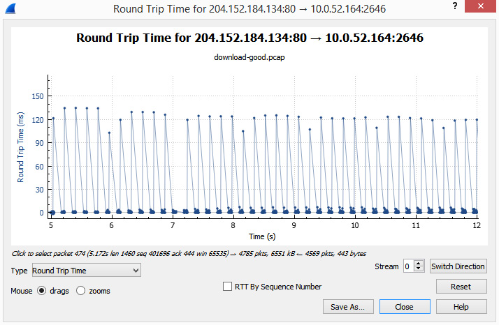
Figure 17.2 – Steady RTT
However, you won't always see a steady RTT, as this value can increase and vary during the course of transmission. When there is latency, you will see an increase in the RTT.
To see the RTT for a particular stream in Wireshark, go to the menu and choose Statistics | TCP Stream Graphs | Round Trip Time, as shown here:
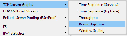
Figure 17.3 – TCP Stream Graphs menu
When you select Round Trip Time, Wireshark will open the graph. Once in, make sure you are viewing the correct stream direction, which you can modify by using the Switch Direction button in the lower right-hand corner.
To see an example of an RTT slowly increasing, follow these steps:
- Open the client-fast-retrans.pcap file in Wireshark.
- Generate a stream graph by going to TCP Stream Graphs | Round Trip Time. Once selected, Wireshark will open the graph, as shown here:

Figure 17.4 – RTT graph for stream 0
When looking at the graph from client-fast-retrans.pcap, we see that the RTT between 230.211.187.172:80 and 74.203.22.229:49683 (or stream 0) is increasing over time. This is most likely due to latency on the network.
Note
We will cover the different types of TCP stream graphs in more detail in Chapter 19, Discovering I/O and Stream Graphs.
Latency refers to how long it takes to transmit a packet and is measured in RTT. When there is high latency, the sender has difficulty sending data, and as a result, less data is able to get to the receiver. Next, let's take a look at throughput.
Measuring throughput
Throughput is how much data is sent and received (typically in bits per second) at any given time. In Wireshark, we can measure this as well as goodput, which is useful information that is transmitted.
Network media can affect throughput. For example, fiber optics has better throughput than copper. Congestion and delays can also affect how much data is getting through. When there is decreased throughput, packet loss can occur, as discussed next.
Experiencing packet loss
When there is latency, data may not be getting through, which can lead to packet loss. Losing or dropping packets on a network occurs for a variety of reasons. Packet loss is determined by the number of packets lost for every 100 packets sent.
Endpoints and applications work to manage transmission delays and network congestion. However, there are times when excessive packet loss occurs, and the network goes into recovery mode. In Wireshark, we see evidence of packet loss with indicators such as keep-alivess, duplicate ACKs, and retransmissions.
Wireshark is capable of identifying many common transmission errors and can calculate delays and interruptions in the data flow by using time values. The following section provides an insight into the significance of time while doing an analysis.
Learning the importance of time values
When doing an analysis on a packet capture, time values can provide an insight into the delays in transmission. In Wireshark, there are choices as to how you can display the time value, which include the following:
- Seconds Since Beginning of Capture
- Seconds Since Previously Captured Packet
- Seconds Since Previously Displayed Packet
It's important to use the correct time format. In most cases, it's best to select Seconds Since Previously Displayed Packet, which will show delays whether or not you used a display filter.
Network latency and transmission errors occur on the network. Fortunately, Wireshark has a way to help identify common issues in the form of coloring rules. The following section outlines Wireshark's coloring rules and how you can use them in your analysis.
Understanding coloring rules
Built within Wireshark are coloring rules or filters, which identify or highlight specific traffic. Locate the default coloring rules by going to the menu and choosing View | Coloring Rules, as shown in the following screenshot:
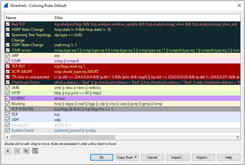
Figure 17.5 – Default coloring rules
Once you are in the Coloring Rules menu, you can edit, delete, or add your own as needed. In addition to using the default coloring rules, you can create and share rules. An example can be found at https://wiki.wireshark.org/Jay%27s_Coloring_Rules.
Each rule is processed until Wireshark finds a match, according to the order shown in the console. To modify the order of a particular rule, select the rule and then drag it to the desired position.
A checkmark on the left-hand side indicates an active rule. To deactivate it, deselect the rule you do not want Wireshark to consider.
To edit a rule, do the following:
- Select and double-click the coloring rule you want to modify.
- You can then edit the name, or the filter used, along with the background and foreground colors.
Although Wireshark can colorize packets, in some cases, the coloring can be distracting. You can disable the coloring rules by selecting the icon, which is generally underneath the Telephony menu item, as outlined in the following screenshot. However, the position of the icon can vary in different versions, platforms, or layouts:

Figure 17.6 – Viewing the coloring rules icon
Wireshark summarizes the coloring rules that are in use in the frame metadata. In addition to the information listed pertaining to the time, frame, and protocols, you will see the coloring rules used. To see an example of the coloring rules summary, follow these steps:
- Open the client-fast-retrans.pcap file.
- Go to frame 20 and expand the frame metadata by clicking the arrow to the right of the Frame 20 label.
- At the bottom of the metadata list, you will see the coloring rules, as shown in the following screenshot:
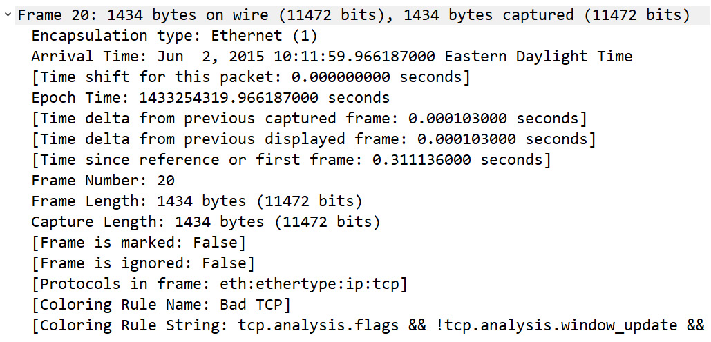
Figure 17.7 – Coloring rules in the frame metadata
When there is trouble on the network, you will most likely see coloring evident in the packet list. The rules provide guidelines on what traffic to home in on during analysis.
Note
For the coloring rules to work, they must be enabled. However, in most cases, the coloring rules are active.
In addition to the colors used in the packet list, there is also a distinct pattern on the right-hand side that is based on the active coloring rules. This pattern represents the Intelligent Scrollbar. Next, let's take a look at how Wireshark incorporates the use of the coloring rules within the Intelligent Scrollbar to easily spot problems.
Exploring the Intelligent Scrollbar
In addition to seeing indications of problems within a capture, you can also easily spot issues using the Intelligent Scrollbar. To see an example of an active Intelligent Scrollbar, go to http://tcpreplay.appneta.com/wiki/captures.html#bigflows-pcap. Once there, download bigFlows.pcap and open it in Wireshark so that you can follow along. Open the capture and then go to frame 586 by doing the following:
- Select the go to specified packet icon.
- In the form box, type 586, then select Go to packet.
- The Intelligent Scrollbar will display indications of network congestion within the packet list, as shown in the following screenshot:
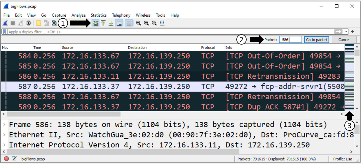
Figure 17.8 – Visualizing network congestion
The Info column header on the right-hand side lists several indications of trouble that warrant further investigation. These include the following:
- [TCP Out-Of-Order]
- [TCP Retransmission]
- [TCP Dup ACK 587#1]
The administrator can click on a color band and go directly to the specified packet in order to zero in on a possible problem. Once you click on a band, Wireshark will adjust the packet list to display the area of concern.
We can see how the coloring rules and Intelligent Scrollbar help to identify transmission errors and trouble spots in the capture. In the next section, we will explore common transmission errors that occur on a network.
Common transmission errors
Long delays in intermediary devices, such as routers and switches, can cause latency, dropped packets, and/or other negative effects. When troubleshooting congestion issues in Wireshark, you may see evidence of transmission errors.
Some common indications include duplicate ACKs, keep-alive segments, and fast retransmissions.
As this information may indicate latency and gaps in the delivery of data, it's important to understand the meaning of what the packets are trying to tell you. Let's start with an overview of duplicate ACKs.
Seeing duplicate ACKs
In a normal TCP conversation, the client recognizes every byte received by transmitting an ACK, with the ACK field value set as the next expected byte. When more than one ACK is sent by the client (with the same ACK field value), this is said to be a duplicate ACK.
To understand what a duplicate ACK is, let's step through a standard TCP transaction:
- In the course of a normal TCP data transaction, TCP sequences and acknowledges every byte of data received.
- The client acknowledges the data received by setting the ACK flag in the TCP header, as shown here:

Figure 17.9 – The TCP ACK flag set
- The client places the value of the next expected byte in the Acknowledgment Number field.
- When the client sends an ACK 180 (acknowledgment number: 180), the client is saying to the server, So far, I've received 179 bytes of data, and I am ready for more (bytes), starting with (byte number) 180, as shown in the following diagram:
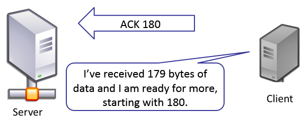
Figure 17.10 – Normal TCP ACK
- The server doesn't wait for confirmation of delivery to send more data. Instead, the data is sent concurrently with the ACKs.
Note
With TCP, an ACK is expectational, in that the ACK is sent with the next expected byte to be sent by the server.
- If the client sends another ACK 180 flag, the client is (again) saying to the server: So far, I've received 179 bytes of data and I am ready for more (bytes), starting with (byte number) 180.
- Wireshark recognizes this as the second ACK 180 flag sent by the client and identifies this packet as a duplicate ACK. This means the client did not receive the next expected byte and is politely asking the server to send the data.
In Figure 17.8, as shown in the Exploring the Intelligent Scrollbar section, you can see a duplicate ACK in frame 589. This indicates that the client is patiently re-requesting the missing data. In addition, in the Info column header, you can see [TCP Dup ACK 587#1]. This means this is the second (or duplicate) ACK flag sent after the original ACK sent in frame 587.
Latency and delays in transmission can be caused by any number of things, such as processing and queuing delays along with general network congestion. As a result, duplicate ACKs may be sent over and over again by the client until it receives the expected data.
Network congestion is part of today's landscape and has many negative effects, such as slow web page retrieval. Another indication of transmission errors and congestion is keep-alive packets, which we will explore next.
Observing keep-alive segments
When communicating with a web server, the client and server both use Hypertext Transport Protocol (HTTP) to communicate with each other. If during a session the network becomes sluggish and both sides begin to experience slow response times, HTTP uses a method called keep-alive. A keep-alive packet doesn't have any data; it has the ACK flag set, and the sequence number is set to one less than the current sequence number.
Keep-alive packets are sent between the client and the server to verify that both sides are still responding. Using this method keeps a session alive instead of dropping the connection and having to go through the expensive negotiation of reestablishing the connection.
If you would like to see an example of a keep-alive packet, go to https://www.cloudshark.org/captures/5618ff446df8. Once open, select Export, found on the right-hand side of the interface, and then select Download the original file, as shown here:
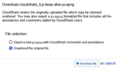
Figure 17.11 – Export file from CloudShark
Open the cloushark_tcp-keep alive.pcapng file in Wireshark. Once open, select packet 158, right-click, and then select Follow | TCP Stream. You can also use the tcp.stream eq 17 display filter. Once you have filtered the traffic, you should see the following:

Figure 17.12 – HTTP keep-alive packets
I have removed the coloring so you can see the exchange of keep-alive packets in frame 153 and frame 158. In this capture, it is most likely that the network is congested, and latency is preventing the exchange of data. As a result, HTTP uses keep-alive packets between both endpoints to keep the session alive.
Therefore, in addition to seeing duplicate ACKs when there is network congestion, you may also see multiple keep-alive packets.
Next, let's take a look at another indication of slow network speeds and congestion: the presence of retransmissions.
Issuing retransmissions
On a congested network, it's common to see retransmissions, fast retransmissions, and spurious retransmissions. All three are related. However, each has subtle differences.
First, let's talk about retransmissions and fast retransmissions on the network.
Recognizing retransmissions
In a TCP connection, each side of a conversation actively monitors the data transaction. When congestion is evident and the data is not getting through, recovery efforts are triggered when certain conditions are met. Depending on the algorithm, you will see retransmissions or fast retransmissions where the server is actively trying to resend the missing data.
Sometimes, the data does get through and the server is not aware that the client has received the data. In that case, the server sends an unnecessary or spurious retransmission.
Sending a spurious retransmission
During the course of the data transaction, the server may resend data that is not needed. The client has previously acknowledged that it received the data, but the server has resent the data, most likely because it did not receive the ACK. This is called spurious retransmission. Although the data is not needed, this can still be a cause for concern, as somehow, the communication to the server has been interrupted.
When just starting out with learning how to do packet analysis, it can be overwhelming. While you may not be able to identify all possible issues, Wireshark provides a guide in the form of curated expert information on the capture. This tool groups common issues together so you can quickly investigate network delays, as we'll explore next.
Discovering expert information
While analyzing a packet capture, you may observe a colored circle in the lower left-hand corner of the interface. That is the Expert Information guide, which is a feature built within Wireshark that helps to alert the network administrator of possible issues once a capture has been made.
As shown in Figure 17.8 in the Exploring the Intelligent Scrollbar section, the expert information icon is a red circle, which indicates an error; this is the highest expert information level.
Return to the bigFlows.pcap packet capture. Double-click the expert information icon in the lower left-hand corner, which will open a console, as shown in the following screenshot:

Figure 17.13 – Expert Information grouped by severity
This may take a few minutes to load, depending on the size of the capture. In addition, there may be a lot of information.
The Expert Information console is a GUI that allows you to see details of what Wireshark identified in the capture, so you can investigate further. The interface is intuitive, with column headers, selection checkboxes, and drop-down lists so you can customize your viewing.
Now, let's take a look at each column header in the following section.
Viewing the column headers
While in the Expert Information interface, I selected Note and then expanded the caret next to Duplicate ACK (#1), as shown:

Figure 17.14 – Note: Duplicate ACK (#1)
Across the top of the interface, you will see column headers. The following bullet points outline what each header indicates:
- Severity: Indicates the severity of the error identified. In the preceding screenshot, the severity is listed as Note.
- Summary: Provides a summary of the error and combines all the errors that are the same under one drop-down summary. For example, in the preceding screenshot, the summary is Duplicate ACK (#1). Once you expand the line, you can drill down into the individual packets to see more details on each error listed.
- Group: Within each summary, there are several common groupings. For example, the items listed under Duplicate ACK (#1) are grouped under Sequence. The following outline some of the groups that you might see:
- Protocol: Lists the main protocol that was in use that caused the alert, such as TCP, as shown in the preceding screenshot.
- Count: Provides a count of the number of references for the particular event grouping. For example, on the top right-hand side of Figure 17.14, we see there is a count of 36104 Duplicate ACK (#1).
As shown, the column headers highlight the details of what the packet contains. In addition, the Expert Information outlines the level of severity by using color, as outlined in the next section.
Assessing the severity
When looking at the Expert Information console, there are five possible categories that indicate the severity of an issue, as shown here:

Table 17.1 – Expert Information severity levels
Having a visual of the issues in the packet capture is helpful, but there are even better ways to present the information. In the next section, we'll learn about ways to sort, search, and display the data.
Organizing the information
When you open the Expert Information console, you'll need to make sense of the data. The interface provides ways to sort and search, along with ways to show only a certain kind of data.
We'll start with an overview of ways to sort data within the interface.
Sorting the data
After you launch the Expert Information console, all the information may not be sorted. As you'll find, you can easily sort any of the column headers. I typically sort the results in order of severity.
To view all the packets for a specific summary, select the caret on the left-hand side of the summary, as shown in Figure 17.14.
If you have applied a display filter, you can select Limit to Display Filter, which is found in the lower left-hand corner, to show only your filtered results. This could be handy if you are troubleshooting a particular conversation and want to only display the filtered conversation.
The default view lists all errors, warnings, notes, and chats. However, you may only be interested in the errors. In that case, you can limit your results by using the drop-down menu in the lower right-hand corner. Once there, you can select or deselect what you would like to display, as shown here:
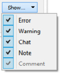
Figure 17.15 – Expert Information | Show categories
In addition, if there are any comments, you can display them as well.
As shown, you can easily sort data within the Expert Information dialog box. In the next section, we'll see how searching data helps to improve your ability to focus on specific issues.
Searching for values
When you need to locate a specific value while in the Expert Information, enter the value in the search box and press Enter. The following screenshot shows the results for the ssdp search:
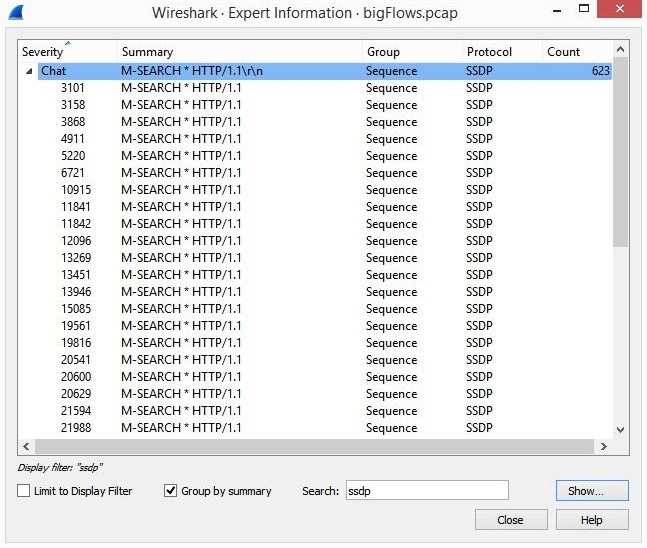
Figure 17.16 – Expert Information search results
The Expert Information console has an advanced menu function. As shown in the following screenshot, when you right-click on a value, you can select any of the menu choices listed:

Figure 17.17 – Expert Information menu choices
Similar to the menu choices offered when you right-click on a field value when in the packet details, you can select any of the following:
- Apply as Filter will select the highlighted conversation and run the filter in the main interface.
- Prepare a Filter will select the highlighted conversation and prepare the filter in the main interface. To run the filter, you must press Enter.
- Find, when selected, will place the variables in the Display Filter in the main interface, as shown in the following screenshot:

Figure 17.18 – Results of the Find menu choice
- Colorize will open the Coloring Rules dialog box and allow you to create a custom coloring rule.
- Look Up will open a browser, do a Google search, and present the results.
- Copy will copy the selected line onto the clipboard. For example, if I right-click on packet 10915 and select Copy, Wireshark will copy the results to the clipboard. I can then paste the results, as follows:
10915 SSDP: M-SEARCH * HTTP/1.1
- Collapse All will collapse the results to a single summary line.
- Expand All will expand the results to show all the packets.
The Expert Information console can provide a great deal of insight into possible problems in a packet capture. Wireshark presents the results in an easy-to-read format in the console, where you can view and analyze any errors, warnings, notes, and chats.
Summary
Networks need to be available nearly 100 percent of the time. A single device failure, malware, or misconfiguration can significantly impact network performance. In this chapter, we reviewed how we measure performance using three main metrics: latency, throughput, and packet loss. We then looked at a few of the many tools available in Wireshark to identify trouble on the network. We discovered the importance of time values and how they factor in discovering latency issues. In addition, we learned how coloring rules can highlight specific types of traffic. We also discovered how any of the rules can be edited, deleted, or moved up or down in priority.
We then looked at the Intelligent Scrollbar, which provides a visual so that we can easily spot and further investigate trouble in a capture. We covered the ways Expert Information helps to alert the network administrator on possible issues once a capture has been made. We summarized by reviewing the Expert Information console, which we can use to drill down on specific issues and subset errors, warnings, notes, and chats.
In the next chapter, we will cover ways to work with large packet captures and break them down into smaller files for analysis. We will look at filtering packets to narrow down the results, as well as reasons and ways to add comments to a single packet or an entire capture. We will then conclude with the many ways and formats that allow us to save and export packet captures.
Questions
Now it's time to check your knowledge. Select the best response, and then check your answers, which can be found in the Assessment appendix:
- ____ is a metric that measures the time it takes to transmit a packet from one point to another and can be measured using RTT.
- Latency
- Packet loss
- Goodput
- Throughput
- ____ is the amount of data that is sent and received (typically in bits per second) at any given time.
- Latency
- Packet loss
- Goodput
- Throughput
- In Wireshark, the _____ is on the right-hand side of the packet list panel and displays a distinct coloring pattern based on the coloring rules set in the application.
- Group metrics
- Time values
- Intelligent Scrollbar
- Goodput meter
- A _____ is a special type of packet that does not have any data. It only has the ACK flag set, so the client knows to keep the session active during an HTTP session.
- Duplicate acknowledgment
- Keep-alive
- Retransmission
- Fast retransmission
- When viewing the expert information icon, a cyan circle indicates a(n) _____, which is general information, unusual errors, or a nonstandard use of a protocol.
- Error
- Warning
- Note
- Chat
- _____ is determined by the number of packets lost for every 100 packets sent.
- Latency
- Packet loss
- Goodput
- Throughput
- It's important to use the correct time format. In most cases, it's best to select Seconds Since _____, which will show delays whether or not you used a display filter.
- 1970-01-01
- Beginning of Capture
- Previously Captured Packet
- Previously Displayed Packet