Chapter 9
Character Studio and IK Animation
At one time or another, almost everyone in the 3D community wants to animate a character. This chapter examines the 3ds Max 2011 toolsets used in the process of character animation. In this chapter, you will learn about two of the three components that make up Character Studio, a full-featured package incorporated into 3ds Max that is mostly for animating bipedal characters, including humans, aliens, robots, and anything else that walks on two feet, though you can have characters with more than two feet in certain situations.
Although Character Studio (CS) creates an instant structure for a character, you will also work with Inverse Kinematics (IK), which creates hierarchical structures for animating individually linked objects.
Character animation is a broad and complex field that nearly everyone wants to experiment with at some point. This chapter introduces you to the basics of using Character Studio and Bones. Further investigation into these tools is a must if you want your animation to be full of life and character.
Topics in this chapter include the following:
- Character animation
- Character Studio workflow
- Creating a biped
- Animating a biped
- Associating a biped with the soldier model
- Using Inverse Kinematics
The character animation CG specialty is easily one of the toughest specialties to master. It takes an exceptional eye and a special insight to become an amazing animator. To use one word, good character animation comes down to nuance. Because we as people move ourselves and are surrounded by other people who move, we are innately critical when a character is not well animated. That is because the detail and nuance in movement is so inherent, so ingrained in our experience, that we never really think twice when we see someone move. We just intrinsically know how they move the way they do. However, we do notice when that nuance is missing in an animation of a person. As observers, we may not know exactly what is missing, but we instinctively know that something is wrong and it looks funny.
When you animate a character, you have to have a keen eye for detail and an understanding of how proportions move on a person’s body. Setting up a CG character to walk exactly like a human being is amazingly complicated. You must account for muscles, bone structures, and a host of other details that most 3D software does not begin to address.
However, good animation for a character is actually not very difficult right out of the box. Character systems such as Character Studio (CS) make it a breeze to set up characters and have them moving in a walk cycle very quickly. Don’t limit your character animation studies to Character Studio, though. While learning and mastering how CS works and how to animate with it, you mustn’t lose sight of the fact that you are trying to learn how to animate as opposed to learning how to run a piece of software. Never let mastery of a software program be your primary mission. You will quickly limit yourself that way.
In other words, once you gain a solid grasp of how CS and other character tools work, use them to learn how to really animate. Character Studio is just a means to an end. You’re here to learn to animate, not to learn how to run CS. Now that we have that out of the way, we can concentrate on getting you comfortable with CS. Have fun!
Character Studio is a system built into 3ds Max to help automate the creation and animation of a character, who may or may not be exactly a biped (two-footed creature). Character Studio comprises three basic components: the Biped system, the Physique and Skin modifiers, and the Crowd system. Biped and Physique are used to pose and animate a single character, and the Crowd system is used to assign similar movements and behaviors to multiple objects in your 3ds Max scene. This chapter covers the Biped and Physique features, but Crowd is beyond the scope of this book.
The first step in the Character Studio workflow is to build or acquire a suitable character model. The model should be bipedal, meaning it stands on two feet. In the future, however, you needn’t limit yourself to strictly humanoid models; CS is perfectly useful for animating anything from a human to a dinosaur to a bumblebee, as long as the model’s configuration allows it. The second step in the process is to skin (bind) the character model to the skeleton so the animation drives the model properly.
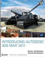
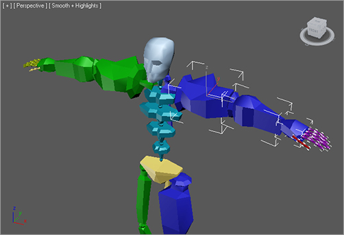
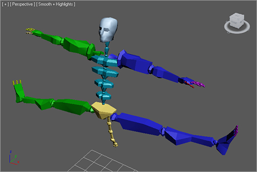
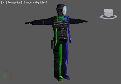
Models should typically be in the reference position known as the “da Vinci pose,” where the feet are shoulder width apart and the arms are extended to the sides with the palms down, as shown in Figure 9-1. This allows the animator to observe all of the model’s features, unobstructed by the model itself, in at least two viewports. This layout of a model is a standard in the CG industry because it facilitates skinning the model to its skeleton.
Figure 9-1: A bipedal character in the reference position

Again, the term bipedal refers to any character with two feet. In 3ds Max, a biped is a predefined, initially humanoid, structure. It is important to understand that you animate the biped that is associated with your model, and not the model itself. Once the model is bound to the skeleton, the biped structure drives the model. You would use the Physique modifier in CS to create that relationship between the skeleton and the model.
Using the Physique modifier ensures that your model follows the biped’s animation. You will work with attaching a model to a biped using Physique later in this chapter. You can also use another 3ds Max methodology, the Skin modifier, to attach the model to the biped skeleton. The differences between the two methodologies are explained next.
Physique versus Skin
Currently, 3ds Max has two modifiers that essentially
do the same thing. Physique and Skin can both be used to transfer the movement of a skeletal system such as a biped to a mesh, making the character move with the skeleton rig. Of the two, Physique is the older modifier. In 3ds Max’s first releases, Character Studio, which included Physique in its package, was developed by Unreal Pictures as the first major plug-in for 3ds Max and was sold as a separate program.
Over time, however, users demanded that a program similar to Physique be included as part of the base 3ds Max package. Autodesk, responsive to the needs of its users, developed the Skin modifier to satisfy the customers’ need. However, when CS was bundled free of charge with 3ds Max, Physique was included, and so the base 3ds Max package included two modifiers to do the same character-skinning task.
Over time, Skin has had numerous improvements that add to its capabilities, while Physique has more or less remained the same. Because both can accomplish the same work, you can choose which one you want to learn. It comes down to personal taste; some users swear by Physique, others swear at it—and the same goes for Skin. Physique is covered in this chapter and will be your introduction to how to attach a model to a biped skeleton. Once you feel you understand the methodology, try your hand at using Skin the next time.
General Workflow
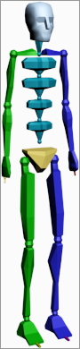
The default biped, shown in Figure 9-2, consists of legs, feet, toes, arms, hands, fingers, pelvis, spine, neck, and head. After your model is ready, you will create a biped and, using its parameters and the Scale transform, fit the biped closely to the model. The better the biped to model relationship, the easier the animation will be.
Figure 9-2: The default biped
Bones and Skin
The Bones system and Skin modifier have capabilities similar to those found in Character Studio. Bones is a series of linked, hierarchical components that are used, in conjunction with the Skin modifier, to control the displacement of a model similar to the Biped and Physique method. Many animators prefer Bones. They appreciate the finer control they are able to achieve over the character’s motion and motion restrictions. With finer control comes more work; Bones requires a more tedious setup process to create a skeleton than Biped.
Once the biped is fit snugly to the model, you select all of the components of the model, not the biped skeleton, and apply the Physique or Skin modifier in a process often referred to as skinning. It may take a while to properly test and refine the relationship between the model and the biped to get it to an acceptable level.
The final step is animating your character. You can accomplish this by adding to the biped any combination of default walk, run, and jump cycles included with CS, then applying any freeform animation to the character, and finally refining the animation keyframes in the Dope Sheet. Don’t expect the default walk, run, and jump cycles to create realistic motion, though. They are just a starting point and must be tweaked to achieve acceptable movements. Character animation is about nuance and subtlety, and those artistic touches take a significant amount of time and effort to master.
In a student or prospective employee’s work, we can immediately spot default or “canned” animations that are straight out of the program’s library of motions. Default cycles are a great place to get your start. Don’t let yourself stop with canned motions, though. You will have to imbue your own sensibility into a character to really make it as a good animator.
The best way to start is to jump in and examine the tools available. In the next section, you will work with a biped and adjust the parameters and components to modify it.
As stated previously, you should create your model first and then create and modify your biped to fit the model. In this section, however, you are going to examine the procedure for creating and modifying a biped first so you can gain an understanding of its capabilities. Later in this chapter, we will revisit the methods for adjusting your biped specifically to match a model.
Placing a Biped in a Scene
Figure 9-3: Click the Systems button.

Let’s create a Biped system for your scene so you can get a feel for how CS works. Unlike many of the objects that you’ve created so far, Biped is located under the Systems category of the Create tab in the Command panel, as shown in Figure 9-3.
Follow these steps to create and adjust a biped:
1. From the Command panel, select Create ⇒ Systems ⇒ Biped.
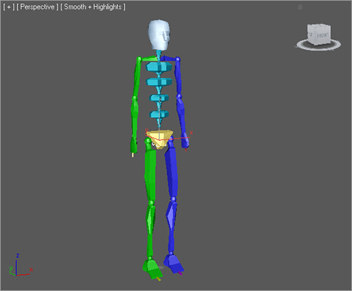
2. Click and drag in the Perspective viewport to create the biped shown in Figure 9-4.
The first click sets the insertion point. Dragging defines the height of the biped system and defines all of the components. All of the biped’s components are sized relative to the biped’s Height parameter.
With this action, you created 30 visible and 5 hidden objects arranged in a linked hierarchy, not just a single object. All of the elements on the left side of the biped’s body are blue, and all of the elements on the right side are green. This coloring scheme is carried throughout 3ds Max.
Figure 9-4: Create a basic biped.
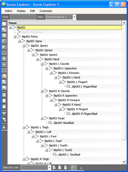
3. Go to Tools ⇒ New Scene Explorer, which opens up a modeless dialog box (one that floats so you can still edit your scene while it is open). Figure 9-5 shows the Scene Explorer that opens when you invoke the New Scene Explorer command; it is for viewing hierarchies, among other things. After you expand each entry, all of the objects are indented from the edge of the dialog box, indicating that they are subordinate to, or children of, the objects above them in the list.
Figure 9-5: The Scene Explorer dialog box
4. Close the Scene Explorer.
5. While the biped is still selected, go to the Command panel and expand the Create Biped rollout if necessary. This rollout is where changes to the biped’s structure are made. You can increase the number of fingers and toes and the number of links in each to match your model. You can add a tail or ponytail by increasing the number of links for these parameters. You can even discard the arms altogether.
Adding neck links will make your biped taller, but adding spine links won’t—it will only subdivide the torso area for more control in the midsection.
6. Change the parameters as you like. The biped in Figure 9-6 includes additional fingers and toes, as well as a tail and a ponytail.
The root object of the hierarchy is named Bip001, for the first biped that you create in a scene, and all the associated objects will have a Bip001 prefix. Changing the name of the object in the Name and Color rollout changes only the name of the root object and does not cascade throughout the hierarchy. Changing the name in the Root Name section of the Create Biped rollout, however, affects all of the objects in the biped.
Figure 9-6: A biped with modified parameters

Modifying a Biped
Bipeds are very generic in appearance. You will rarely, if ever, use the default biped in an actual animation beyond learning CS. Luckily, bipeds have a complete set of tools available for modifying their structure and their behavior to match a model. You will have to select an appropriate editing mode to access the appropriate tools to adjust your biped. This section covers the tools used to adjust the size of a biped’s individual elements.
If you haven’t already, create a biped in your scene as discussed earlier. To begin modifying the biped, follow along here:
1. Clear your selection set by clicking the Select Object button (![]() ) in the Main toolbar and then clicking on any blank area of a viewport. Nothing in your scene should be selected.
) in the Main toolbar and then clicking on any blank area of a viewport. Nothing in your scene should be selected.
2. Click any part of your biped to select it. Bipeds react differently than other objects. Selecting any single component of the biped opens the entire Biped object for editing.
3. Click the Motion tab of the Command panel (Figure 9-7). The purpose of a biped is to create an animation, so all of the biped’s parameters, including those that control animation as well as appearance, are consolidated under the Motion tab of the Command panel, and not under the Modify tab as you may initially think.
Figure 9-7: Biped parameters are on the Motion tab of the Command panel.

4. In the Biped rollout, click the Figure Mode button (![]() ) to display the rollouts that pertain to the biped’s configuration, not its animation or footstep control. The Figure Mode button turns dark to indicate the current mode that the system is using.
) to display the rollouts that pertain to the biped’s configuration, not its animation or footstep control. The Figure Mode button turns dark to indicate the current mode that the system is using.
5. Expand the Structure rollout to access the same parameters that were used when you first created the biped to adjust its basic configuration. Make any additional modifications that you choose.
In the Body Type drop-down menu at the top of the Structure rollout, you can change the overall appearance of the biped from the default Skeleton to Male, Female, or Classic. The body type has little to do with the biped’s capabilities and is more a matter of preference.
6. Select the biped’s left upper arm. In the Main toolbar, click the Select and Rotate button.
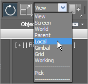
7. In the Main toolbar, set the reference coordinate system for the current Rotate tool to Local, as shown in Figure 9-8. Most transforms that are applied to a biped are applied in the Local coordinate system so they are relative to the object rather than the world or the current viewport.
Figure 9-8: Select the Local coordinate system.
8. Place your cursor over the green Y-axis ring of the Rotate Transform gizmo and drag upward to rotate the upper arm upward, as shown in Figure 9-9. Notice that the arm rotates at the shoulder as it’s supposed to. The pivot point is already placed correctly.
All of the pivot points for the biped elements are already placed at the top of the objects. For example, the upper arm pivots at the shoulder, the lower arm pivots at the elbow, and the hand pivots at the wrist. This is one of Character Studio’s great time savers.
9. Click the Scale transform in the Main toolbar and change the reference coordinate system to Local.
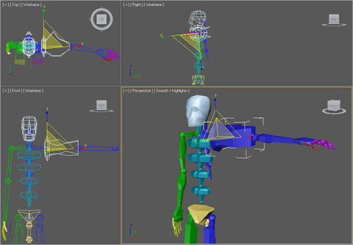
10. Click and drag the X-, Y-, and Z-axis handles of the Scale Transform gizmo individually, as shown in Figure 9-10. The Y and Z handles make the upper arm large or small, causing your biped to bulk up or thin out. Dragging the X handle changes the length of the upper arm. For the best reference, you should observe the changes in all of the viewports while you’re adjusting the scale.
11. Select and adjust the left lower arm, hand, and fingers to suit yourself. Don’t worry about the right side yet; we will discuss that shortly.
Figure 9-9: Rotating a biped component
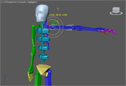
Figure 9-10: Use all the viewports to monitor the size and shape.
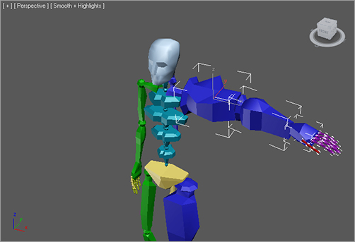
12. Select each of the spine links and scale them to give your biped a nice, tapered torso. Dragging the X handle upward will scale the links vertically and push the elements above them upward, increasing the height of the biped. Scaling the top spine link in the positive Z direction will push the clavicles and all other arm components outward, as shown in Figure 9-11. The clavicles are linked to the middle of the top spine link and can be protruded by that link. If necessary, scale the clavicle to extend beyond the top spine link.
Figure 9-11: Scaling the top spine link pushes the arms outward.

13. Select and scale the pelvis to spread the hips out further.
14. Similar to what you did in steps 11 and 12, use the Scale transform to adjust the scale of the biped’s left upper and lower leg and foot to your liking (Figure 9-12).
Figure 9-12: Scale the legs and foot to the appropriate size.

As you can see, creating a biped is fairly simple. You simply click and drag to place the system, and drag to set the biped’s height and proportionate size. You then adjust the parameters of the structure in the Motion panel. Finally, you position and adjust the size of each of the biped’s components using the transforms to fit the needs of your intended character model.
Copying and Pasting Postures
Most characters are basically symmetrical, with some variations in their surface appearance to make them look less perfect and a bit more natural. Character Studio allows you to set the structure and form—called the posture—for elements on one side of a biped’s body and then paste those features to the elements on the other side. For instance, when the length, width, and pose of the left arm, hand, and fingers are tweaked to your satisfaction, you can paste the same dimensions and orientations to the relative components on the right side. You don’t need to model the opposite side independently.
To follow along with these steps, you can continue with the previous exercise or open CSBiped1.max from the Chapter 9 files on this book’s companion web page at www.sybex.com/go/intro3dsmax2011.
1. Select the biped and access Figure mode if necessary.
2. Double-click the left upper arm. Double-clicking an object selects that object as well as all the objects below it in the hierarchy. In this case, you are also selecting the lower arm, hand, and all finger joints when you double-click the upper arm (Figure 9-13).
Figure 9-13: Select the entire arm and hand by double-clicking the upper arm.
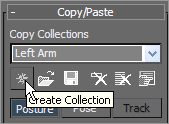
3. Open the Copy/Paste rollout.
4. Postures must be saved as collections prior to being pasted. Click the Create Collection button (as shown in Figure 9-14) and then rename the collection from the default Col01 to Left Arm.
Figure 9-14: Create the collection.
5. Click the Copy Posture button just below the Posture button to copy the selected posture to the Clipboard. A preview of the copied posture will appear in the Copied Postures area of the Command panel, as shown in Figure 9-15.
Figure 9-15: Copy the posture.

6. Click the Paste Posture Opposite button (![]() ). The size, scale, and orientation of the selected objects will be applied to the reciprocal objects on the opposite side of the biped, as shown in Figure 9-16.
). The size, scale, and orientation of the selected objects will be applied to the reciprocal objects on the opposite side of the biped, as shown in Figure 9-16.
Figure 9-16: Pasting a posture to the other side of a biped
Copied postures are not limited to being pasted within a single biped; they can also be pasted to other bipeds. Simply copy the posture, select any part of another biped, and then click the Paste Posture button (![]() ).
).
7. Repeat steps 2 through 6 to copy the posture of the left leg to the right leg.
As you’ve seen in this section, modifying a biped’s appearance and posture is pretty easy! You select any of the biped’s components, use the Rotate and Scale transform tools, and change the components’ size and orientation as needed for your character. Later in this chapter, you will explore the procedures for fitting a biped to a specific model to ensure a smooth animation setup.
Now is a good time to save your scene before you proceed to the next section.
Bipeds can be animated in several ways, including footstep-driven animation and freeform animation. Just as it sounds, with footstep-driven animation you add visible Footstep objects to your scene and direct the biped to step onto those footsteps at particular points in time to suit your animation intent. Footsteps can be added individually or as a set of walk, run, or jump steps; they can be moved or rotated to achieve the desired result and direction. When using footstep-driven animation, the legs and feet of the biped are not the only things animated; the hips, arms, tails, and all other components are animated too. A short animation sequence can generate hundreds, or even thousands, of animation keys.
Footstep-driven animation is often a good starting point, but it is rarely the complete solution to your animation needs. For example, there is no method for turning a biped’s head or raising its arms using footsteps.
Even when footsteps are used to create the initial movement of a biped, freeform animation must be used to augment and tweak the character’s motion. Freeform animation is when you animate the components of the biped manually, as you would animate any other object, such as a bouncing ball. To refresh yourself, you can refer back to Chapter 8, “Introduction to Animation,” which includes using the Auto Key method and the Track View—Curve Editor mode.
Animation keys that are added to the selected Biped objects appear in the track bar, just like other objects, where they can be moved, modified, or deleted to adjust the animation. Some character animators forgo footstep-driven animation altogether and use freeform animation exclusively. They enjoy the finer control freeform animation gives them when they create keys only where they choose and not throughout the automated footsteps. In this section, you will explore both the footstep-driven and freeform methods for animating a biped.
Moving the Biped into Place
As a system, bipeds can’t be moved by using the Move transform in the Main toolbar. To position a biped correctly, you must first select and move the root object using the Body Vertical and Body Horizontal buttons. We will go over this in the following steps.
Continue with the previous exercise or open CSBiped2.max from the Biped Scene Files folder on the companion web page. If you open the web page file, select the biped and enter Figure mode.
Figure 9-17: Keep track of the position as you scale.

1. In the previous exercise, if you scaled either of the leg elements along the X-axis, the feet of the biped moved off the construction plane—also known as the Home Grid—as shown in Figure 9-17. The Home Grid is where the new footsteps will be placed, so you will want the biped’s feet to be at that elevation.
2. Turn on the grid, if necessary, using the G shortcut key. Maximize the Front viewport and zoom so that you can see the dark, horizontal line indicating the construction plane, the feet, and the pelvis. The pelvis isn’t really important at this point, but the root object located inside of it is.
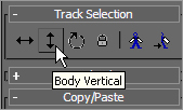
3. In the Track Selection rollout, click the Body Vertical button (see Figure 9-18). This selects the diamond-shaped Bip001 object, which is the root object of the hierarchy, and activates the Move Transform gizmo.
Figure 9-18: The Body Vertical button
4. Use the Move Transform gizmo to move the biped until the feet rest on the Home Grid, as shown in Figure 9-19.
Figure 9-19: Moving the biped to the Home Grid
5. Switch back to a four-viewport display.
Adding Footsteps
Adding footsteps is as simple as adding a specified number of steps with a particular gait, or clicking the mouse button to place footsteps individually. We’ll try both methods in this chapter. First, let’s begin by placing a series of footsteps. Here’s how:
1. With the biped selected, click the Footstep Mode button in the Biped rollout (![]() ). The rollouts change to display the tools for adding and controlling a biped’s motion. The Footstep mode and Figure mode are exclusive; you cannot be in both modes at the same time.
). The rollouts change to display the tools for adding and controlling a biped’s motion. The Footstep mode and Figure mode are exclusive; you cannot be in both modes at the same time.
Figure 9-20: Create footsteps with a walk gait.

2. In the Footstep Creation rollout, make sure that the walk gait is selected and then click the Create Multiple Footsteps button, as shown in Figure 9-20, to open the Create Multiple Footsteps dialog box.
3. In the dialog box that appears, you will assign Footstep properties for the number of steps you want, the width and length of each step, and which foot to step with first. Set the number of footsteps to 8 and leave the other parameters at their default values, as shown in Figure 9-21. Click the OK button.
4. Zoom out in the Perspective viewport to see the footsteps you just created (Figure 9-22). Look at the Time Slider, and note that the scene now ends at frame 123; that’s 23 more frames than the 100 frames the scene had at the beginning of this chapter. 3ds Max recognized that it would take the biped 123 frames, or just over 4 seconds, to move through the eight steps that it was given.
Figure 9-21: Creating multiple footsteps
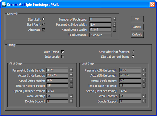
Figure 9-22: Zoom out to review the footsteps.
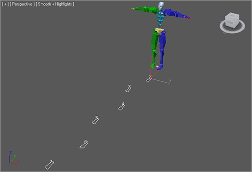
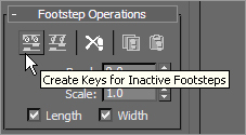
Figure 9-23: The Create Keys for Inactive Footsteps button
5. Click the Play Animation button (![]() ) in the Playback Controls area. What happens? Nothing. The biped must be told explicitly to create animation keys for the steps that you have just added to the scene. Drag the Time Slider back to frame 0.
) in the Playback Controls area. What happens? Nothing. The biped must be told explicitly to create animation keys for the steps that you have just added to the scene. Drag the Time Slider back to frame 0.
6. In the Footstep Operations rollout in the Command panel, click the Create Keys for Inactive Footsteps button shown in Figure 9-23. The biped will drop its arms and prepare to walk through the footsteps that are now associated with it.
7. Click the Play Animation button again. This time the biped walks through the footsteps with its arms swinging and its tail swaying back and forth.
Controlling the View
Now the problem is that if you zoom in on the biped and play the animation, it walks off the screen so you cannot see the end of the walk cycle. What good is that? Motion cycles can be very linear and difficult to track, so Character Studio contains the In Place mode to follow a biped’s animation. While in the In Place mode, the biped will appear to stay in place while the scene moves around it in relation. The In Place mode cannot be used in a Camera viewport, however.
Figure 9-24: Expand the Modes and Display rollout.

1. Go to frame 0 then zoom in on the biped in the Perspective viewport.
2. At the bottom of the Biped rollout, click the Modes and Display text with the plus sign to the left of it, as shown in Figure 9-24. This is actually a small rollout located inside of another rollout that expands to show additional display-related tools.
Figure 9-25: Click the In Place Mode button.

3. In the Modes and Display rollout, click the In Place Mode button (see Figure 9-25).
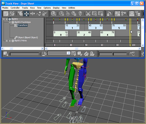
4. Click the Play Animation button again. This time the biped will appear to be walking in place while the footsteps move underneath it, as shown in Figure 9-26. Stop the animation playback when you’re ready.
Figure 9-26: The biped does not change position in the viewport when it is in the In Place mode.

Using the In Place mode helps you work out the way a character moves without having to navigate throughout 3D space with your viewport; so you won’t need to hunt down your biped. It is important to closely watch the cycle movement and try to finesse parts to suit the character, to make it the best animation you can.
The In Place mode is great for tweaking your animation cycle because the viewport moves with the character in 3D space and you can concentrate on how its body is moving.
Walk, Run, or Jump?
What is the difference between a walk, run, or jump gait in 3ds Max? The difference is not speed or length of stride; it’s the number of feet that the biped places on the ground at any given moment. In a walk gait, the biped has either one foot or both feet on the ground at all times. During a run sequence, the biped has either one foot on the ground or, in midstride, zero feet on the ground. When the biped is executing a jump sequence, it has either both feet on the ground or zero feet on the ground while it is airborne. You can use any of these gaits or mix and match them to begin your character’s motion.
Adding a Run-and-Jump Sequence
Creating a footstep cycle does not limit you to these footsteps. Any extra footstep sequences can be added to a biped. These new footsteps are appended to any existing footsteps. This, in turn, extends the length of the animation, if necessary, to accommodate the additional footsteps. In the next exercise, you will add footsteps to the existing animation cycle.
Continue with the previous exercise or open CSBiped3.max from the Biped Scene Files folder on the companion web page, select any biped component, and access Footstep mode from the Motion panel.
1. Click the Run button (![]() ) in the Footstep Creation rollout. This will apply a run gait to any footsteps you will add to your current footsteps in the Create Multiple Footsteps dialog box.
) in the Footstep Creation rollout. This will apply a run gait to any footsteps you will add to your current footsteps in the Create Multiple Footsteps dialog box.
2. Click the Create Multiple Footsteps button to open the Create Multiple Footsteps dialog box.
3. Change the number of footsteps to 10 and click the OK button.
4. In the Footstep Operations rollout, click the Create Keys for Inactive Footsteps button to associate the new footsteps with the biped.
5. Click the Play Animation button. The biped walks through the first 8 steps and then runs through the next 10. As you can see, the run sequence meets the definition of a run, but it is far from realistic. In the next activity, you’ll learn how to add to or modify a biped’s motion with freeform animation to make a better cycle.
6. Click the Jump button in the Footstep Creation rollout, and then click the Create Multiple Footsteps button.
7. In the Create Multiple Footsteps dialog box, set the number of footsteps to 4 and click the OK button. Because a jump is defined as a sequence with either two feet or zero feet on the ground at a time, four jump steps will equal two actual jumps.
8. Click the Create Keys for Inactive Footsteps button to associate the new jump footsteps with the biped.
9. Press the Play Animation button. The biped will walk, run, and then end the sequence with two jumps.
The Actual Stride Height parameter in the Create Multiple Footsteps dialog box determines the height difference from one footstep to the next. For example, to animate your biped walking up a flight of stairs, you would set Actual Stride Height to the same value as the riser height of each stair, so each footstep would correspond to a stair-step.
Adding Freeform Animation
Good animation rarely, if ever, comes from a first try. When you set your keys initially, you will need to edit them to suit good timing and form, as well as to fix any issues that may come up. Character animation is relational: When one part of the body is in one movement, another part of the body is in an accompanying or supportive or even opposite form of movement. When you are walking and your right leg swings forward in a step, your right arm swings back and your left arm swings out to compensate. With character work, you have to remain cognizant of the entire body of the character and how it moves.
As with everything that is automated, the walk, run, and jump cycles that CS creates definitely need some work before they will be acceptable as good animation; they definitely lack the human touch, which is the hallmark of good animation. For example, based on a standard CS cycle, the biped’s head never turns, the torso is very stiff, and the arms swing similarly regardless of the gait type selected. When animating using CS, you will need to add the little nuances of movement that make animation interesting and personable. You will need to add animation to the biped to gain personality. Luckily, you can easily add or modify the biped’s existing animation keys with freeform animation using the Auto Key button and the Dope Sheet. The following exercises contain examples of freeform animation.
Moving the Head
Any character’s head will move along while the character walks. The following steps will guide you through the process of creating head movement for your biped. Continue with the current project scene or open the CSBiped4.max file from the Biped Scene Files folder on the companion web page.
1. Select one of the biped’s components and, if necessary, exit the Footstep mode by clicking the Footstep Mode button.
2. Drag the Time Slider to frame 50, approximately the point when the biped lifts its left foot off of footstep number 2.
Footsteps are numbered, starting with the number 0 and initially alternating from the left to the right side. They are also color-coded, corresponding to the biped, with blue footsteps on the left and green footsteps on the right.
3. Select the biped’s head and note the animation keys that appear in the track bar, as shown in Figure 9-27.
Figure 9-27: Selecting a component of the biped reveals all of that object’s animation keys in the track bar.

Figure 9-28: Delete the keys on either side of frame 50.
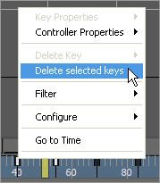
Figure 9-29: Rotate the head to the left and up.
4. In the track bar, select the two keys on either side of the current frame, right-click either one, and then delete them (see Figure 9-28).
5. Click the Auto Key button (![]() ) to turn it on.
) to turn it on.
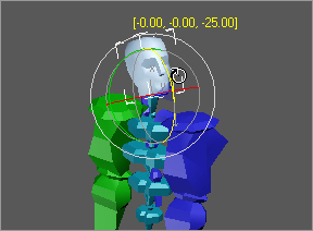
6. Click the Rotate Transform button and rotate the head, as shown in Figure 9-29, to the left and up, as if the character sees somebody in a second floor window off-screen. A new key will be created at frame 50, recording the time and value of the head’s rotation.
7. Scrub the Time Slider back and forth. Watch the head rotate from a neutral position to the orientation that you created and then rotate back to the neutral position.
8. Select all the keys between frame 50 and frame 100 (but not keys at frames 50 and 100). Delete them. This will make room for the new key that you are about to create. If animation keys are too close together, the animation could appear jerky.
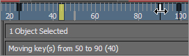
9. Select the key at frame 50, hold the Shift key down, and drag a copy of the key to frame 90, as shown in Figure 9-30. Use the readout at the bottom of the 3ds Max window to drag the key with precision. Copying the key will cause your biped to hold that neck pose for 40 frames, or about one and one-third seconds. Scrub the Time Slider to review the animation.
Figure 9-30: Drag to copy the key.
10. Select the biped’s left upper arm.
11. In the track bar, select and delete all keys between frames 50 and 100. The animation keys for the arms define their swing motion. If you scrub the Time Slider or play the animation, the biped will hold its arm unnaturally stiffly for 60 frames because you deleted the animation keys between two points where it holds its hand forward. That’s OK; we’re just making room for some new keys.
12. Move the Time Slider to frame 60. This is the location for the first new animation key.
Moving the Arms
Now it’s time to animate the arms, which are essential components in any walk cycle. To do so, follow these steps:
1. Rotate the upper arm upward, so that it points to the same location at which the head is looking.
2. Continue adjusting the biped’s left arm, hand, and fingers until they appear to be pointing at something, as shown in Figure 9-31. You may need to turn off In Place mode to zoom in to the arm and hand.
Figure 9-31: Rotate the biped’s arm, hand, and fingers to assume a pointing posture.

3. Double-click on the left upper arm to select it and all of the components below it in the hierarchy.
4. In the track bar, select the key at frame 60, hold the Shift key down, and drag it to frame 85 to create a copy of that key.
5. Drag the Time Slider and watch the Perspective viewport. The biped will walk for a bit, notice something off-screen, point at it, and drop its arm while looking forward again before breaking into a run and then a jump.
6. Click the Auto Key button to turn it off.
Completing the Motion Sequence
The CSBiped5.max file in the Biped Scene Files folder on the companion web page contains the completed scene to this point.
For additional practice, add keys to the animation of the biped’s arms when it jogs through the run cycle. For example, when the left foot is fully extended and the heel plants on the ground, the right arm should be bent at the elbow and swung forward and slightly in front of the biped’s body. As the right foot swings forward during the next step, the right arm should swing backward and assume a nearly straight posture. Bend each of the spine links and swing both arms backward to prepare the biped for each of the jumps. Use the Body Vertical button in the Track Selection rollout to lower the pelvis into a pre-launch position, as shown in Figure 9-32, before the biped launches into its upward motion. Remember to make sure the Auto Key button is turned on to record all the changes that you make as animation keys.
Figure 9-32: Use the Body Vertical button to position the biped for a jump.

Modifying Animation in the Dope Sheet
What if you need to change the animation that is generated with CS? To that end, you will need to edit the keyframes of the biped once you are happy with the base animation cycle. For this, you need to use the Track View–Dope Sheet. The Track View–Curve Editor, as you have already seen, is used to edit the function curves between animation keys; however, the Track View–Dope Sheet interface is cleaner and is used to edit the specific value and position of the keys. It is not a different set of keyframes or animation; it’s just a different way of editing them. Furthermore, access to editing the footstep keys is available only in the Dope Sheet. In this exercise, you will add individual footsteps and modify the footstep timing in the Dope Sheet to make the biped dance and jump.
Control of footstep animation is not available in the Track View–Curve Editor. You can, however, convert footstep animation to freeform animation using the Convert button (![]() ) in the Biped rollout. All existing animation will be retained, but the footstep-driven feature will be replaced by simple function curves that can be edited in the Curve Editor.
) in the Biped rollout. All existing animation will be retained, but the footstep-driven feature will be replaced by simple function curves that can be edited in the Curve Editor.
Adding Footsteps Manually
With the following steps, you will manually add footsteps to your biped character:
Create a new scene with a biped or open CSBiped6.max from the Biped Scene Files folder on the companion web page. This is a biped with no footsteps applied.
1. Enter the Footstep mode.
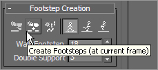
2. In the Footstep Creation rollout, click the Walk button and then the Create Footsteps (at Current Frame) button, as shown in Figure 9-33.
Figure 9-33: The Create Footsteps (at Current Frame) button
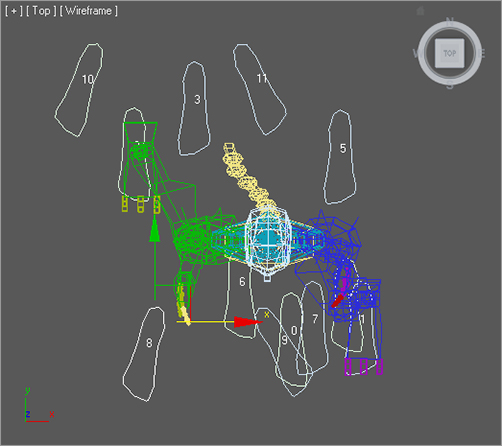
3. In the Top viewport, click in several locations around the biped to place alternating left and right footsteps to your liking.
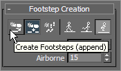
4. Change the gait to a jump, and then click the Create Footsteps (Append) button (see Figure 9-34) to create additional footsteps. Create about 12 footsteps in all.
Figure 9-34: The Create Footsteps (Append) button
5. When you are done, use the Move and Rotate transforms to adjust the footstep locations and orientations as desired. Your Top viewport should look similar to Figure 9-35.
Figure 9-35: Manually place the footsteps in the Top viewport.
6. In the Footstep Operations rollout, click the Create Keys for Inactive Footsteps button and then play the animation.
7. Character Studio doesn’t have a collision detection feature, so it is very possible that limbs will pass through one another, which is quite uncomfortable in real life. If this happens, the footsteps must be modified to eliminate these conditions. If necessary, move any footsteps that cause collisions or other unwanted conditions during the playback.
Using the Dope Sheet
In Chapter 8, you experimented with the Track View–Curve Editor and learned how to adjust the values of animation keyframes while observing the values between keyframes displayed as a function curve. When the Track View is in Dope Sheet mode, frames are displayed as individual blocks of time that may or may not contain keys. Although you cannot see the flow from key to key that the Curve Editor displays with its curves, the Dope Sheet mode has its advantages. For one, the Dope Sheet has the ability to add Visibility tracks to control the display of an object, as well as Note tracks for adding text information regarding the keys. Notes are helpful when you are working with other animators, or even when you want to remind yourself of something later on regarding that animation.
Using the Track View–Dope Sheet, you can adjust the point in time when a foot plants on or lifts off the ground, how long the foot is on the ground, and how long the foot is airborne. Rather than appearing as single-frame blocks in the Dope Sheet, like other keys do, footstep keys appear as multiframe rectangles that identify each foot’s impact time with the footstep. Let’s try the Dope Sheet on for size here:
1. Exit the Footstep mode.
2. In the Main toolbar, choose Graph Editors ⇒ Track View - Dope Sheet. The Dope Sheet will open.
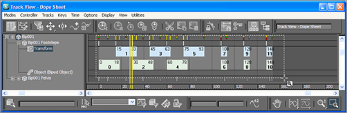
3. In the Navigation pane on the left, scroll down until you find the Bip001 entry. Expand the Bip001 and Bip001 Footsteps entries. The footstep keys appear as rectangles in the Key pane. As expected, the left keys are colored blue and the right keys are colored green. If necessary, click the Zoom Region button (![]() ) in the lower-right corner of the Dope Sheet window and drag a zoom window around the footstep keys, as shown in Figure 9-36. The region will expand to fit the key pane.
) in the lower-right corner of the Dope Sheet window and drag a zoom window around the footstep keys, as shown in Figure 9-36. The region will expand to fit the key pane.
Figure 9-36: Zoom to the Footstep keys.
4. Select a few Footstep keys in the panel on the right.
The white dot on the left side of a selected key identifies the frame when the heel of the biped’s foot first impacts the footstep. Similarly, the white dot on the right side of a selected key identifies when the biped’s foot lifts off a footstep (Figure 9-37). A blue key overlapping a green key indicates that both feet are on the ground. A vertical gray area with no footstep indicates that the biped is airborne and neither foot is on the ground.
Figure 9-37: The dots indicate when contact begins and ends. You can drag a dot to change the duration of contact.

5. Select the first key (numbered 0), place the cursor over the right edge of the key (as shown in the second image in Figure 9-37), then drag the dot to the right to extend the length of time that the biped’s foot is on the ground.
You can’t move the end of one footstep key beyond the beginning of another one, and you must maintain a one-frame gap between same-side footsteps. You can’t move a key to a point in time beyond the active time segment, nor can you modify keys for footsteps that have been created but not yet associated to the biped. In addition, footsteps must be at least two frames long.
6. The double vertical line in the Dope Sheet’s Key pane is another Time Slider that allows you to scrub through the animation. Drag the Dope Sheet’s Time Slider to a point in time when the biped is airborne, as shown in Figure 9-38.
Figure 9-38: Drag the Time Slider until the biped is airborne.
A biped’s airborne time is calculated using the standard physics values for acceleration due to gravity: 32 ft/s2 or 9.8 m/s2. The biped does not simply hover at a user-defined altitude by moving it on the Z-axis and setting a key, as you would do with most other 3ds Max objects. Therefore, increasing the airborne time by increasing the gap between footsteps will boost the height to which the biped rises, acting against the gravitational force pushing it downward.
7. Select the last four jump keys and drag them to the right to create a gap approximately 30 frames wide, as shown in Figure 9-39. This will cause the biped to be airborne for about one second.
Figure 9-39: Create a key gap to get your biped airborne.

It is possible to move a footstep beyond the limits of the active time segment in the Dope Sheet. For example, in a 100-frame animation, you can move the last footstep to start at frame 105 and end at frame 123. When you play the animation, it will begin to loop at frame 100, and you will never see the animation created by the last keys. Use the Alt+R key combination to extend the active time segment to include all existing keys.
8. Click Alt+R to lengthen the active time segment, then move the Time Slider to the frame when both feet are planted before the jump starts. Turn on the Auto Key button.
9. Deselect any keys by clicking a blank area in the Key pane.
10. To prepare the biped to leap, select the Bip001 object and move it downward, causing the biped to bend its knees more. Rotate the spine links, neck, and head to bend the torso forward and tuck the chin. Rotate both arms backward into a pre-jump posture, as shown in Figure 9-40. Be sure to choose Local as the reference coordinate system for the Rotate transform.
11. Move the Time Slider forward until the biped is at the apex of the jump. Rotate the biped’s components into positions you like, such as the split shown in Figure 9-41. Delete any animation keys that may interfere with your desired motion, and turn off Auto Key.
The CSBiped7.max file in the Biped Scene Files folder on the companion web page contains the completed exercise so you can check your work.
As you saw in this section, there are several ways to animate a biped, including the footstep-driven method, the freeform method, and a combination of techniques. You can also modify the animation in the track bar, with the Auto Key button, and with Track View–Dope Sheet. The next section addresses the methods for associating your biped with a 3D model, also known as skinning.
Figure 9-40: Prepare your biped to jump.

Figure 9-41: Position your biped in mid-jump.
Associating a Biped with the Soldier Model
The purpose of a biped is to be the portal through which you add animation to your model, rather than animating the model itself using direct vertex manipulation or deforming modifiers. Any motion assigned to a biped is passed through it to the nearest vertices of the associated model, essentially driving the surfaces of the model. For this reason, it is important that the biped fit as closely as possible to the model.
Creating and Modifying the Biped
In the following steps, you’ll create and adjust a biped to fit to a character model. Set your project to the Soldier project available for download from the companion web page at www.sybex.com/go/intro3dsmax2011. You can then open the CSSoldier.max file from the Scenes folder of the Soldier project. It contains a completed soldier model in the reference position. Be sure to set the project folder to the root folder for the CSSoldier project.
1. With the soldier model file open, select the character, right-click in a viewport, and choose Freeze Selection. This will prevent you from inadvertently selecting the soldier instead of the biped.
2. Create a biped with a height about the same as the soldier’s. This will size most of the biped’s parts similar to those of the soldier, as shown in Figure 9-42.
Figure 9-42: Create a biped about the same height as the soldier model.
3. With the biped still selected, click the Motion tab of the Command panel and enter Figure mode. Changes to the biped’s features or pose must be made in Figure mode to be retained by the system.
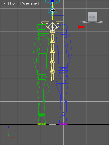
4. Use the Body Vertical and Body Horizontal buttons in the Track Selection rollout and the Move Transform gizmo to position the biped’s pelvis in the same location as the model’s pelvis, as shown in Figure 9-43. With the pelvis located properly, scaling the legs or spine to match the model’s proportions will be much easier. Check to make sure the location is correct in all of the viewports.
As you did earlier in this chapter, you will modify one side of the biped to fit the model and then paste that posture to the other side.
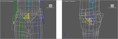
5. In the Front viewport, select the pelvis and scale its width so that the biped’s legs fit inside the soldier’s legs. Scale the pelvis in the Right viewport so that it roughly encompasses the soldier’s lower region. See Figure 9-44. Make sure the coordinate system for the Scale transform is set to Local.
Figure 9-43: Match the positions of the biped pelvis and the model pelvis.

Figure 9-44: Scale the pelvis to fit.
Viewing Frozen Objects
If your background color is similar to the default shade of gray that Max uses to depict frozen objects, the model may seem to disappear against the background. There are several solutions to this situation:
- You can go to Object Properties, turn off Show Frozen as Gray, turn on See-through, and set all viewports to Smooth + Highlights mode.
- You can change the shaded color in the Customize User Interface dialog box (Customize ⇒ Customize User Interface ⇒ Colors).
- You can change the viewport background color in the Customize User Interface dialog box (Customize ⇒ Customize User Interface ⇒ Colors).
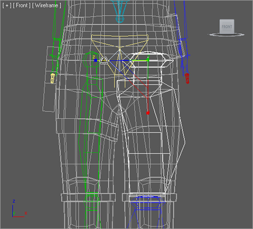
6. Select the biped’s left upper leg, and then scale it along the X-axis until the knee aligns with the soldier’s knee. Scale it on the Y- and Z-axes until it is similar in size to the soldier’s thigh, as shown in Figure 9-45.
7. Select the biped’s left calf. In the Right viewport, rotate the calf to match the model and then scale it on the X-axis until the biped’s ankle matches the soldier’s ankle. You may need to select the left foot and use the Move transform, in the Front viewport, to orient the calf to the model. Scale the calf to match the proportions of the soldier’s calf.
Figure 9-45: Scale the length, width, and depth of the biped’s upper leg to match the soldier’s thigh.
Modifying a biped to match a model can be a time-consuming task that requires continual tweaking and modification. Moving the foot as described in the previous step may require that the upper leg’s proportions be readdressed. Don’t expect to perform this task quickly without making any revisions to components on which you have previously worked. The better the biped matches the model now, the easier the animation will be later.
Figure 9-46: Increasing the Ankle Attach parameter to move the ankle
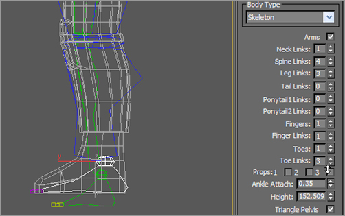
8. Continue working down the leg by scaling the biped’s foot to match the soldier’s. Be sure to check the orientation of the foot in the Top viewport. In the Structure rollout, use the Ankle Attach parameter to move the biped’s ankle slightly backward, as shown in Figure 9-46.
Figure 9-47: Match the model’s boot and the biped’s toe.
9. In the Structure rollout, change the number of toes to 1 and toe links to 2. Because the soldier is wearing boots, a single, wide toe will suffice.
10. Scale and move the biped’s toe to match the model’s boot. Be sure to scale the toe links on the Z-axis, as shown in Figure 9-47.
11. Double-click the left upper leg to select it and all of the objects below it in the hierarchy. Create a collection and then copy/paste the posture of the left leg to the right as you did in the “Copying and Pasting Postures” section in this chapter. The model is not perfectly symmetrical; make any necessary changes to the right side of the biped.
Adjusting the Torso and Arms
Similar to the method used to adjust the legs, you will use the Scale and Rotate transforms to fit the biped to the model. The locations of the arms rely on the scale of the spine links. You can continue with your file from the previous exercise or open CSSoldier2.max from the Scenes folder of the Soldier project available on the companion web page. Just make sure your project is set to the Soldier project.
1. In your scene (or the one from the web page), select the biped, and then access Figure mode, if you need to.
Figure 9-48: Match the biped’s clavicles to the model.

2. Select each of the spine links in turn, and then rotate and scale them to fit the soldier’s torso. Only the lowest spine link can be moved, and this will move all of the links above it as well. Each spine link should be scaled down slightly on the X-axis to lower the biped’s clavicles to match the model’s, as shown in Figure 9-48.
3. Move, rotate, and scale the left clavicle as required to place the biped’s shoulder socket in the proper location.
4. Scale and rotate the left upper arm and left forearm using the same techniques you used to adjust the biped’s legs.
5. Scale and rotate the left hand as required to fit the model.
Once the fingers have been adjusted, you cannot go back and change the number of fingers or finger links. If you do, all modifications to the fingers will be lost.
Figure 9-49: Match the biped’s fingers to the model’s.
6. The hands need only two fingers (the second finger is actually the thumb) and two links each. Adjust the biped’s fingers to match the model’s fingers, as shown in Figure 9-49. This can be one of the most tedious tasks in character animation, depending on the complexity and orientation of the model’s fingers. Take your time and get it right. (Would you rather do it right or do it over?)
7. When you are done, paste the posture to the right side of the biped and make any required changes.
Adjusting the Neck and Head
Figure 9-50: Adjust the neck links to match the model’s neck.

The neck and head will seem easy to adjust when compared to the hands. You need to make sure the neck links fill the soldier’s neck area, and scale the head to fit. Follow along here:
1. In the Structure rollout, increase the number of neck links to 2.
2. Move, scale, and rotate the neck links to match the proportions of the model’s neck, as shown in Figure 9-50.
Figure 9-51: Matching the head

3. Move and scale the head to the approximate size of the soldier’s head, as shown in Figure 9-51.
That’s it. The biped has been created and adjusted to fit the 3D model, and half the battle is over. Next you will tie the biped to the model and make adjustments to the skinning process. Now would be a good time to save your work and take a break.
Applying the Physique Modifier
The Physique modifier is the tool used to skin the 3D model to the biped so that all of the biped’s animation is passed through to the model. It’s important to remember that the modifier is applied to the model and not to the biped. Continue with the previous exercise or open CSSoldier3.max from the Scenes folder of the Soldier project on the companion web page to follow these steps:
1. Right-click in any viewport and select Unfreeze All from the Quad menu to unfreeze the soldier model.
2. Select all of the biped’s components by double-clicking the Bip001 object.
If you have trouble double-clicking the Bip001 in a dense model, try selecting Bip001 using the Select from Scene dialog box and then pressing Ctrl+Page Down to select everything below it in the hierarchy.
3. In the Named Selection Sets field in the main toolbar, enter the name SoldierBiped to save the biped as a named selection set (see Figure 9-52). This makes it easier to select all the components for the biped in one fell swoop by selecting its name from the drop-down list on the Main toolbar.
By creating named selection sets, you can quickly access all of the desired components by selecting the named selection set from the drop-down list on the main toolbar. For reference, see Chapter 3, “The 3ds Max Interface,” for the icons and functions of the named selection sets.
Figure 9-52: Create the name selection set.

4. Select the Soldier model and click the Modify tab of the Command panel.
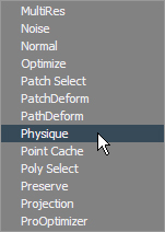
5. Expand the Modifier List and select the Physique modifier, as shown in Figure 9-53.
Figure 9-53: Select the Physique modifier.
6. In the Physique rollout, click the Attach to Node button (![]() ). The button will turn dark and wait for you to identify the root object in the hierarchy that controls the mesh.
). The button will turn dark and wait for you to identify the root object in the hierarchy that controls the mesh.
7. Press the H key to open the Pick Object dialog box. This method will be easier than trying to click on the object directly in a cluttered scene. Select the Bip001 Pelvis object and click the Pick button, as shown in Figure 9-54.
8. In the Physique Initialization dialog box, accept the defaults and click the Initialize button. The cursor will briefly turn into a coffee cup to indicate that the initialization is in progress. It will return to normal when the process is complete.
Figure 9-54: Use the Pick Object dialog box to select the root object in a cluttered scene.

Testing the Model
The most time-consuming part of the process is complete. You have created a biped, adjusted all of its component parts to fit your model, and applied the Physique modifier to link the model to the biped. The next step is to test the model by adding animation.
1. Select any element of the biped and click the Motion tab of the Command panel.
2. Enter Footstep mode.
3. Add a footstep sequence as you did in the “Animating a Biped” section of this chapter. Don’t forget to create keys for the inactive footsteps. Exit Footstep mode when you are done.
4. Activate In Place mode, and then zoom and pan the Perspective viewport to get a good view of the action.
5. Exit Footstep mode, then select the SoldierBiped named selection set from the drop-down list on the Main toolbar.
6. Right-click in any viewport and choose Hide Selection from the Quad menu to hide the biped and obtain an unobstructed view of the model.
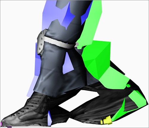
7. Click the Play Animation button. Your soldier will walk through the scene. It should be similar to the rendered soldier shown in Figure 9-55.
Figure 9-55: The rendered soldier during a walk cycle

As you can see, you still need to do a little work to successfully rig this character. Certain parts of the model seem to drag other nearby parts of the model along with them. This is particularly visible in the feet and arms. This is fixed in the next section.
Tweaking Physique
Each element in the biped has an area of influence, called an envelope, that determines which parts of the model it affects. The biped’s left foot, for instance, should control the movement of only the model’s left foot and the lower part of the ankle. In our case, the envelopes extend to affect some of the vertices on the opposite side. To fix the envelopes, follow this procedure:
1. Right-click in the viewport and choose Unhide by Name from the quad menu. In the Unhide dialog box, click Display ⇒ Expand All. Select all of the Biped objects, then click the Unhide button to unhide the biped.
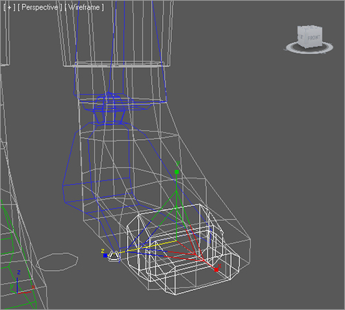
2. Scrub the Time Slider until the left foot rests on the ground after its first step. In the Right viewport, zoom into the feet and legs then render the viewport. Figure 9-56 shows the condition where the left foot drags along some of the vertices from the right foot.
Figure 9-56: There is a problem with the feet.
3. Select the mesh, then, in the Modify panel, click the Hide Attached Nodes option at the bottom of the Physique Level of Detail rollout. This will turn on the sides of the biped temporarily and display the links as thin orange lines.
Figure 9-57: Select the Envelope sub-object level.
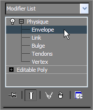
4. In the Modifier Stack, expand the Physique modifier and select the Envelope sub-object, as shown in Figure 9-57.
5. Select the orange links for the left foot and toes. The inner and outer envelopes appear as shown in Figure 9-58. Also, notice that the model’s vertices that are affected by the links are displayed in the viewport as small crosses.
Figure 9-58: Select the Envelope sub-object level

Figure 9-59: Reduce the radial scale
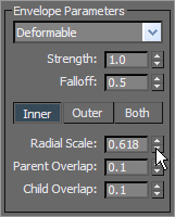
6. In the Envelope Parameters section of the Blending Envelopes rollout, click the Inner button, then reduce the Radial Scale value (see Figure 9-59) until the envelope just encompasses the boot in the Front viewport. Clicking the Inner button causes changes to affect only the inner bound of the envelope.
7. Repeat the procedure with the Outer button selected and watch the vertices from the opposite foot become unselected as the envelope shrinks.
8. Switch to the Right viewport and use the Strength parameter and the Scale transform, alternately with the Inner and Outer buttons selected, to adjust the size and shape of the envelopes. The goal is to have the foot links affect only the boot and ankle.
9. Repeat this procedure with the remaining links in the model. You can use the Parent Overlap and Child Overlap options to determine how much one link affects the vertices controlled by the links before or after it in the hierarchy. You may also want to add some freeform animation to make the character livelier.
The completed Character Studio Soldier exercise can be found in the CSSoldierComplete.max file in the Scenes folder of the Soldier project on the companion web page.
As we mentioned at the beginning of the chapter, Character Studio is a very complete character animation package, and we’ve barely scratched the surface here. There are tools for saving biped configurations and sequences of animation. You can mix animation sequences from different files to create an entirely new motion. When the model does not skin as well as you need, you can use envelopes to refine the skinning process further, define vertices to be excluded from a specific Biped object’s influence, or include bulge conditions to define the model’s behavior depending on the angle between subsequent biped elements. The list goes on, but the good news is that the CS tutorials and help system that ship with 3ds Max are very thorough, and you should find the information in those places to expand your Character Studio skills once you have a solid footing with the basics of CS. It’s important to realize that animation requires nuance, and the best animation with the simplest rig and setup will beat a mediocre animation created with a more wonderful, complicated, ingenious setup.
When a hierarchy is set up through linking, the result is a kinematic chain. As you saw in Chapter 8, transforms are passed from a parent object to all of the child objects down the chain. Imagine your arm is a system of linked 3ds Max objects; when you pivot your forearm (the parent) at the elbow, your hand (the child) and your fingers (the descendants) are also transformed to maintain the relationship between the objects. This is known as Forward Kinematics (FK) and is the default method of passing transforms in a hierarchy.
When Inverse Kinematics (IK) is used, the child object is transformed while the parent and ancestor objects maintain their relationships throughout the chain. Using the same arm example, lifting your arm by grabbing and pulling up on a finger would raise the hand, which would raise the forearm, causing a curl at the elbow. With IK, the end of the chain, the child, is positioned in your animation and the rest of the chain upstream rotates and pivots to fit the new layout of the chain to achieve a possible pose. IK setups require the use of an IK solver to determine how the parent objects react to the child transforms and joint constraints to prevent unnecessary twists in the motion.
In the following exercise, we will play some more with toys of war by linking a machine gun mounted on a tank model. Here, the goal is to arrange the IK setup so that the gun pivots vertically at the joints only and then pivots at the turret.
Linking the Objects
The machine gun unit consists of the gun itself, two two-component pivot assemblies, two shafts, and the turret. The gun is at the top of the hierarchy, and the turret is at the bottom.
1. Open the IKGun1.max file from the Biped Scene Files folder on the companion web page.
2. Begin by linking the Gun object to the PivotTop object, the cylindrical object near the gun. The PivotTop object will flash briefly to signify that is has been linked. If you are having difficulty selecting the proper object directly, press the H key to open the Select Parent dialog box.
3. Continue creating the hierarchy by also linking the PivotTopRing to PivotTop, PivotTop to Shaft1, and then Shaft1 to PivotBottom.
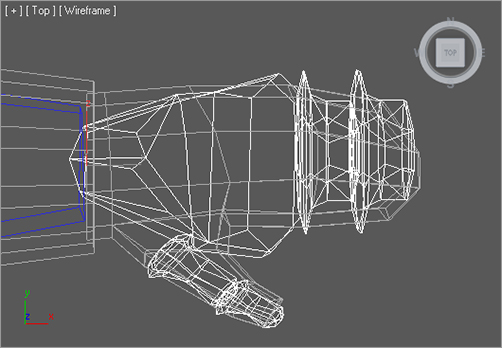
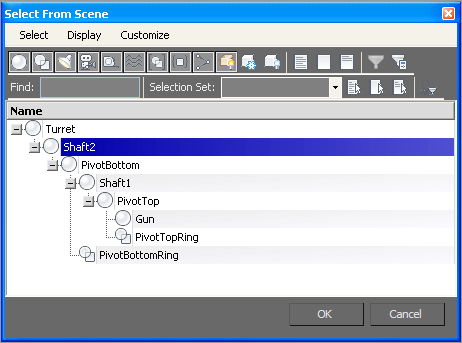
4. Complete the setup by linking PivotBottomRing to PivotBottom, PivotBottom to Shaft2, and Shaft2 to Turret. If you open the Select from Scene dialog box and make sure Display Subtree is checked, you hierarchy will look like Figure 9-60.
Figure 9-60: The Select from Scene dialog box showing the hierarchy
Creating Joint Constraints
The gun assembly should be able to rotate in only certain ways. The gun itself should pivot only perpendicular to the PivotTop object, for example. This is accomplished by constraining the Rotate transform for the PivotTop object, the parent of the gun, to a single axis. The transforms can further be restricted by limiting the range of motion an object can rotate within an acceptable axis. This method is used to prevent the gun barrel from rotating to the point where it disappears within the tank body to which it may be attached. Both of these tasks are accomplished under the Hierarchy tab of the Command panel, as you will see in the following steps:
1. In the Command panel, click the Hierarchy tab (![]() ).
).
Figure 9-61: The Interactive IK button
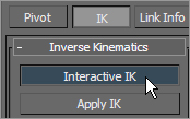
2. Click the IK button and then, in the Inverse Kinematics rollout, click the Interactive IK button, as shown in Figure 9-61. The IK button will turn light gray to signify which family of rollouts is displayed. The Interactive IK button will turn dark to indicate that this feature is active and any transforms applied to objects in the hierarchy are applied in IK mode.
3. In the Perspective viewport, select and move the Gun object along the X-axis. The gun’s orientation changes and all of the hierarchy elements, including the turret, change to maintain the connection, but they all rotate oddly. This is because the orientation at the joints is not constrained to a single axis or limit of degrees.
4. Undo any transforms that were applied.
5. Select the PivotTop object. In the Rotational Joints rollout, uncheck the X Axis and Z Axis Active check boxes.
Figure 9-62: Drag the To: spinner to –40.

6. Check the Limited check box in the Y Axis section. Decrease the From parameter to approximately –65 by dragging the spinners. The Pivot and its children will rotate in the viewport and then snap back to their original orientations when the mouse is released. Drag the To spinner to approximately –40, as shown in Figure 9-62. Limiting the orientation restricts how far the object can rotate in a particular axis, and dragging the spinners instead of typing in the values gives visual feedback regarding the axis about which the object is rotating.
7. Select Shaft1 and uncheck the Active option for the X-, Y-, and Z-axes in the Rotational Joints rollout. Repeat the process for the Shaft2 and Gun objects. None of these objects needs to rotate on their own; they just need to follow their parent objects.
8. Select the PivotBottom object. Check the Active and Limited options in the Y-axis area. Set the From value to –4 and the To value to 30. Uncheck the X Axis and Z Axis Active options.
9. Select the Turret object. Only the Z Axis option should be checked so the turret can rotate only laterally, and not flip over. Do not check the Limited option; the turret should be able to rotate freely.
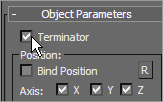
10. In the Object Parameters rollout, check the Terminator option to identify the turret as the top object in the IK structure(see Figure 9-63).
Figure 9-63: Check the Terminator option.
11. Select the Gun object and then click the Link Info button at the top of the Hierarchy panel. In the Rotate section of the Locks rollout, check the X option, as shown in Figure 9-64. The gun should now not rotate on any axis except the local X-axis.
Figure 9-64: Lock the X Rotate axis.

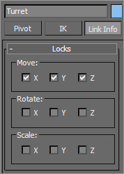
12. Select the Turret object and check the X, Y, and Z options in the Move section (see Figure 9-65) to lock any movement for the turret. The turret should be fixed in place. In a complete 3ds Max scene, the turret would be linked to a larger structure to define its transforms.
Figure 9-65: Lock all the Move axes for the Turret.
13. Click the IK button at the top of the Hierarchy panel, and then click the Interactive IK button again to turn it on if necessary. Test your IK chain by moving the gun. As it moves, the other objects in the chain will reorient to maintain the proper relationships with their parent objects.
14. Turn off the Interactive IK button when you are done.
Applying the IK Solver
An IK solver calculates the controls required to position and orient the members of an IK chain when one or more members is moved or rotated. The IK solver defines the top of the chain and identifies the goal, or the base of the chain. The IK solver precludes the need to activate the Interactive IK mode in the Hierarchy panel whenever IK is required.
The two appropriate IK solvers for this situation are the HI (History Independent) solver and the HD (History Dependent) solver. The HI solver is better suited for long animation sequences and character animation, and the HD solver is better suited for machine animation. Because this animation is for a machine, in this case a tank, the HD solver will be used here.
Continue with the previous exercise or open the IKGun2.max file from the Biped Scene Files folder on the companion web page.
1. Undo any transforms that were applied in your own scene during the previous exercise.
2. Choose Edit ⇒ Hold from the Main menu. Some IK operations, including applying an IK solver, are not always undoable through the Undo command. If the result of the IK solve is not correct, choose Edit ⇒ Fetch to restore your scene to the point just before you executed the Edit ⇒ Hold.
Figure 9-66: A line stretches from the gun’s pivot to the cursor.

3. Select the Gun and choose Animation ⇒ IK Solvers ⇒ HD Solver. A rubber band line will stretch from the gun’s pivot point to the cursor, as you can see in Figure 9-66.
4. Place the cursor over the Shaft2 object and click to define it as the end of the IK chain. The IK chain should now be bound to the object that has been designated as the Terminator.
When the cursor is moved over the other viewports while an IK solver is being assigned, the view will update to show the rubber banding line projecting from the object to the cursor in that particular viewport. The viewport does not have to be the active viewport for this viewport change to occur.
5. The End Effector acts as the pivot point of the Terminator object and can be used to straighten out the chain without actually moving the child object. On the Motion panel, in the IK Controller Parameters rollout, click the Link button in the End Effectors area and then click on the turret. Turret appears in the End Effector field.
6. Select the gun and use the Move transform to test your IK setup. Moving the gun forward, backward, up, or down will now cause the two pivots to rotate within their limits.
The HD solver’s IK components are not listed in the Select Objects dialog box, because they act on behalf of the objects to which they are assigned. To modify any of its properties, select the object and open the Motion panel of the Command panel. The IK Controller Properties rollout contains the options for modifying the IK chain.
This chapter introduced you to two powerful tools for reducing the time and effort required to animate objects and characters. Character Studio is a fantastic tool that speeds up the process of character animation. Using the Biped system, you can quickly create and adjust the substructure that controls a 3D model. Once the Physique modifier associates or skins the model to the biped, character animation can be added using footstep-driven or freeform animation.
IK is used throughout mechanical design and character animation, and it is another 3ds Max tool that you may find invaluable once its workflow becomes second nature to you. The exercises in this chapter examined the basics of an IK setup and the basic use of an IK solver for a mechanical animation of a gun. The IK setups can include several IK chains controlling the transforms for different components of the same model. Easily selected controls can be placed in the scene for simple selection and manipulation of a complex model’s components. IK can also be used for organic character animation, because 3ds Max has different types of IK for character work as well (such as the HI IK or Limb Solver IK). This chapter covered only one type of IK (using the HD solver) for a simple use of IK. Most practical applications will use the HI system; however, for the purposes of this book, familiarizing you with the simpler HD solver primes you for further study in 3ds Max IK systems.