

Operations
This chapter discusses the interfaces that are available to monitor and manage configurations using Parallel Sysplex InfiniBand coupling links.
The following topics are covered:
•Managing your InfiniBand infrastructure
•z/OS commands for PSIFB links
•Coupling Facility commands
•Hardware Management Console and Support Element tasks
•PSIFB Channel problem determination
•Environmental Record, Editing, and Printing
7.1 Managing your InfiniBand infrastructure
One thing that you need to be aware of when you start using InfiniBand links is a greater need for strong system management practices. Strong practices will make management of the InfiniBand infrastructure easier and reduce the possibility of operational errors.
Prior to InfiniBand, each coupling link was only able to be associated with one channel-path identifier (CHPID) and one sysplex. So if you accidentally disconnected the wrong coupling link, you would only lose access from one CHPID, and only one sysplex would be affected. Also, because of the one-to-one relationship between links and CHPIDs, if you have two (or more) online links to a CF, you knew that you had two (or more) working physical links.
However, with InfiniBand, you can have multiple CHPIDs assigned to a link. So a link might be in use by multiple sysplexes. Therefore, if you accidentally disconnect one InfiniBand link, you can remove access for multiple CHPIDs, which can impact multiple sysplexes.
In addition, prior to zEC12 and zBC12, it was not possible to determine the relationship between CHPIDs and physical InfiniBand links from RMF reports or by using z/OS commands. As a result, you might actually be down to just one working physical link but it would not be obvious. When you look in z/OS, you could see multiple CHPIDs online and therefore not realize that you have a single point of failure.
zEC12 provided significant enhancements in the manageability of InfiniBand links. Just about all the information you are likely to need about an InfiniBand CHPID is now available both on the z/OS console, and also in RMF.
Because of the performance characteristics of InfiniBand links, you might find that you need fewer physical coupling links than you had with previous link types. Most clients are likely to find that two InfiniBand links will provide sufficient bandwidth to meet their coupling needs. You need, though, to ensure that your InfiniBand link infrastructure does not contain any single points of failure; because a single InfiniBand adapter supports either two or four ports, ordering a minimal configuration might result in both links being on the same adapter.
Also keep in mind that STP might be using InfiniBand links to transmit timing signals between processors. STP works at the CHPID level, so if you were to physically vary all the CHPIDs associated with an InfiniBand link offline, STP would no longer be able to use that link1.
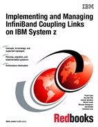
For these reasons, it is especially important to keep current information available for the operators, system programmers, and hardware engineers that clearly shows the relationships between physical links, which HCA and port they are connected to, which CHPIDs are associated with that port, and which sysplexes are using those CHPIDs. They should also have easy-to-use documentation that shows how to retrieve this information from the Support Element (SE) if the system is on a CPC prior to zEC12. Figure 7-1 shows an example of the type of table you might use. This chapter is intended to show how to manage your InfiniBand infrastructure, and how to obtain information to help you create and verify your documentation.
Figure 7-1 Documenting InfiniBand infrastructure
This chapter provides an overview of the interfaces and tools that are available to operate and monitor Parallel Sysplex InfiniBand (PSIFB) coupling links:
•z/OS commands for PSIFB managing coupling links
•Corresponding CFCC commands
•Hardware Management Console (HMC) and Support Element (SE) tasks related to PSIFB coupling links
7.2 z/OS commands for PSIFB links
To successfully manage an InfiniBand configuration, you need to be able to display the status of the components in the current configuration, to understand and be able to control the status of the CF, and to be able to take paths on and offline. As described in Chapter 4, “Migration planning” on page 63, there can be situations where you want to take a link offline on both the z/OS and CF ends; we describe the CF commands to achieve this in 7.3, “Coupling Facility commands” on page 202.
In a normal production environment, several z/OS images are typically attached to a given CF image. When you display the status from the z/OS systems, you will see information about the z/OS end of the links to the CFs. When you display information from the CF side, you will be presented with information about the CHPIDs that are used to connect that CF to the members of the sysplex. Information about links between two CFs will be provided in both the output from the CF and also from z/OS.
7.2.1 z/OS CF-related commands
The following z/OS commands are used to display the PSIFB coupling links and status. You enter the z/OS commands at a z/OS console.
D CF,CFNAME=yyyy
|
Tip: zEC12 delivered significant enhancements to the D CF command. This section shows the command on a CPC prior to zEC12 and also on a zEC12.
It is important to note that the CF does not have to be running on a zEC12 or zBC12. If z/OS is running on a zEC12 or later, detailed information will be provided about the z/OS end of the link. If the CF is running on a zEC12 or later, detailed information about that CF’s end of any CF-to-CF links will be provided.
|
zEC12 and later
The D CF,CFNM=yyyy command displays the status of the named CF and detailed information about the connections to that CF. Example 7-1 shows the output from this command. It shows detailed information about the CF with the name FACIL04, which is the name that was defined in the Coupling Facility Resource Management (CFRM). The output of this command (which was issued from a z/OS system on a zEC12) contains details about the following items:
•The processor and logical partition (LPAR) that the CF resides in
•Storage utilization in the CF
•The Coupling Facility Control Code (CFCC) level
•The CHPIDs that are defined as having access to the CF
•A list of the device numbers and associated subchannels for the CF
•Information about any peer CFs and how they are connected to this CF
Example 7-1 D CF,CFNAME=FACIL04 output
COUPLING FACILITY 002817.IBM.02.0000000B3BD5 1
PARTITION: 2F CPCID: 00
CONTROL UNIT ID: FFFC
NAMED FACIL04
COUPLING FACILITY SPACE UTILIZATION
ALLOCATED SPACE DUMP SPACE UTILIZATION
STRUCTURES: 1426 M STRUCTURE DUMP TABLES: 0 M
DUMP SPACE: 20 M TABLE COUNT: 0
FREE SPACE: 2208 M FREE DUMP SPACE: 20 M
TOTAL SPACE: 3654 M TOTAL DUMP SPACE: 20 M
MAX REQUESTED DUMP SPACE: 1 M
VOLATILE: YES
CFLEVEL: 17
CFCC RELEASE 17.00, SERVICE LEVEL 10.29
BUILT ON 07/30/2013 AT 10:28:00
STORAGE INCREMENT SIZE: 1 M
COUPLING FACILITY HAS 0 SHARED AND 1 DEDICATED PROCESSORS
DYNAMIC CF DISPATCHING: OFF
COUPLING FACILITY IS NOT STANDALONE
...
2
PATH PHYSICAL LOGICAL CHANNEL TYPE AID PORT
B1 / 0723 ONLINE ONLINE CIB 12X-IFB3 000A 02
B5 / 0724 ONLINE ONLINE CIB 12X-IFB3 001A 02
BA / 0727 ONLINE ONLINE CIB 1X-IFB 001D 01
BB / 0728 ONLINE ONLINE CIB 1X-IFB 001D 02
COUPLING FACILITY SUBCHANNEL STATUS
TOTAL: 78 IN USE: 78 NOT USING: 0 NOT USABLE: 0
OPERATIONAL DEVICES / SUBCHANNELS:
FC54 / 2A12 FC55 / 2A13 FC56 / 2A14 FC57 / 2A15
...
REMOTELY CONNECTED COUPLING FACILITIES
CFNAME COUPLING FACILITY
-------- --------------------------
3 FACIL03 002827.IBM.02.00000000B8D7
PARTITION: 3F CPCID: 00
CHPIDS ON FACIL04 CONNECTED TO REMOTE FACILITY
RECEIVER: CHPID TYPE
96 CIB
99 CIB
SENDER: CHPID TYPE
96 CIB
99 CIB
The output of this command shows information from the coupling link perspective, as explained here:
1 The output provides the type and serial number for the processor that contains the CF LPAR and the ID of the LPAR that the CF resides in.
2 Information is provided for each CHPID that is defined to access the CF. Specifically, it displays:
•The CHPID and the VCHID number, for example, CHPID B1 and VCHID 0723.
•The physical status, ONLINE in this case. Also, if the CHPID is running in degraded mode, the display will say “DEGRADED” and the speed that the link associated with that CHPID is running at.
•The logical status, ONLINE in this case.
•The channel type now includes not only the fact that the CHPID is for an InfiniBand link. It also displays the adapter speed (1X or 12X) and the mode (IFB or IFB3).
•The Adapter ID (AID) and Port. This is really vital information to help you determine if there are any single points of failure in the connection to this CF. Ideally, every CF will be connected using at least two different AIDs. In the worst case, if all CHPIDs are on the same AID, they should at least be spread across more than one Port.
3 FACIL03 is another CF. It might be connected to FACIL04 to enable the use of System Managed Duplexing, or it might be connected to transmit STP signals between the two processors. This section contains information about the CHPIDs that are used to connect the two CFs, and the type of each CHPID. The CHPIDs are sorted by receiver and sender depending on the CHPID configuration. If the same CHPID is displayed under both sections, the same CHPID is capable of acting as a receiver and a sender.
In this example, because FACIL04 is in a z196, detailed information about the CF-to-CF CHPIDs is not provided. However, Example 7-2 contains an example of the information that is provided by a CF that is running on a zEC12. This information is from a CF that was running on the zEC12 and connected to FACIL04.
Example 7-2 Sample CF-to-CF CHPID information about zEC12
FACIL04 002817.IBM.02.0000000B3BD5
PARTITION: 2F CPCID: 00
CHPIDS ON FACIL06 CONNECTED TO REMOTE FACILITY
RECEIVER: CHPID TYPE
B1 CIB 12X-IFB3
B5 CIB 12X-IFB3
SENDER: CHPID TYPE
B1 CIB 12X-IFB3
B5 CIB 12X-IFB3
5
5Any CHPIDs that are not operational for the selected CF are listed. If you make dynamic changes to the processor that the CF is running on, and those changes remove CHPIDs from the CF LPAR, those CHPIDs will be listed in this part of the display. Even though they are no longer in the configuration for that LPAR, the CFCC remembers that it was using that link previously, and will continue to list the CHPID in the NOT OPERATIONAL section until the CF is deactivate and reactivated.
Remember that each z/OS that is connected to the CF could potentially be using different CHPIDs to communicate with the CF. Also, it is possible for a CHPID to be offline in one z/OS system, but online in another z/OS in the same processor. Therefore, to obtain a complete picture of the connectivity to the CF, issue the command on all members of the sysplex. You can easily achieve this by using the ROUTE command, for example, RO *ALL,D CF,CFNM=yyyy.
|
Tip: More information about each CHPID is provided by RMF, both in Monitor III and in a new Channel Path Details RMF Post Processor report. For more information about the enhanced RMF support, refer to Appendix A, “Resource Measurement Facility” on page 233.
|
Pre-zEC12
The D CF,CFNM=yyyy command displays the status of the named CF and connections to that CF. Example 7-3 shows the output from this command. It shows detailed information about the CF with the name FACIL04, which is the name that was defined in the Coupling Facility Resource Management (CFRM). The output of this command (which was issued from a z/OS system on the z10 in Example 7-3) contains details about the following items:
•The processor and LPAR that the CF resides in
•Storage utilization in the CF
•The Coupling Facility Control Code (CFCC) level
•The CHPIDs that are defined as having access to the CF
•A list of the device numbers and associated subchannels for the CF
•Information about any peer CFs and how they are connected to this CF
Example 7-3 D CF,CFNAME=FACIL04 output
D CF,CFNM=FACIL04
IXL150I 12.09.50 DISPLAY CF 662
COUPLING FACILITY 002817.IBM.02.0000000B3BD5 1
PARTITION: 2F CPCID: 00
CONTROL UNIT ID: FFF2
NAMED FACIL04
COUPLING FACILITY SPACE UTILIZATION
ALLOCATED SPACE DUMP SPACE UTILIZATION
STRUCTURES: 0 M STRUCTURE DUMP TABLES: 0 M
DUMP SPACE: 20 M TABLE COUNT: 0
FREE SPACE: 3635 M FREE DUMP SPACE: 20 M
TOTAL SPACE: 3655 M TOTAL DUMP SPACE: 20 M
MAX REQUESTED DUMP SPACE: 0 M
VOLATILE: YES STORAGE INCREMENT SIZE: 1 M
CFLEVEL: 17
CFCC RELEASE 17.00, SERVICE LEVEL 04.18
BUILT ON 10/26/2011 AT 13:31:00
COUPLING FACILITY HAS 0 SHARED AND 1 DEDICATED PROCESSORS
DYNAMIC CF DISPATCHING: OFF
CF REQUEST TIME ORDERING: REQUIRED AND ENABLED
COUPLING FACILITY SPACE CONFIGURATION
IN USE FREE TOTAL
CONTROL SPACE: 20 M 3635 M 3655 M
NON-CONTROL SPACE: 0 M 0 M 0 M
SENDER PATH PHYSICAL LOGICAL CHANNEL TYPE 2
B7 / 0704 ONLINE ONLINE CIB
B8 / 0705 ONLINE ONLINE CIB
B9 / 0731 ONLINE ONLINE CIB
BA / 0732 ONLINE ONLINE CIB
BB / 0733 ONLINE ONLINE CIB
BC / 0734 ONLINE ONLINE CIB
BD / 0735 ONLINE ONLINE CIB
BE / 0736 ONLINE ONLINE CIB
COUPLING FACILITY SUBCHANNEL STATUS
TOTAL: 56 IN USE: 56 NOT USING: 0 NOT USABLE: 0
OPERATIONAL DEVICES / SUBCHANNELS:
FCD7 / 4F46 FCD8 / 4F47 FCD9 / 4F48 FCDA / 4F49
...
REMOTELY CONNECTED COUPLING FACILITIES
CFNAME COUPLING FACILITY 3
-------- --------------------------
FACIL03 002097.IBM.02.00000001DE50 4
PARTITION: 0E CPCID: 00
CHPIDS ON FACIL04 CONNECTED TO REMOTE FACILITY
RECEIVER: CHPID TYPE
80 CIB
86 CIB
SENDER: CHPID TYPE
80 CIB
86 CIB
NOT OPERATIONAL CHPIDS ON FACIL04 5
A5 A7 A9 AB
The output of this command shows information from the coupling link perspective, as explained here:
1 The output provides the type and serial number for the processor that contains the CF LPAR and the ID of the LPAR that the CF resides in.
2 Information is provided for each CHPID that is defined to access the CF. The information in the PATH column is the VCHID number. You can use this information to display the VCHID information about the Support Element. On the Support Element, you can determine which AID and Port is associated with that CHPID.
3 In some cases, you might notice that the CF being reported on is also listed as a remote CF. This happens when the CF is in the same processor as the system the command was issued from, and is a corollary of the use of peer mode links. In this example, FACIL04 is on a different processor than the z/OS system, so FACIL04 is not listed as a remote CF for FACIL04.
4 FACIL03 is another CF. It might be connected to FACIL04 to enable the use of System Managed Duplexing, or it might be connected to transmit STP signals between the two processors. This section contains information about the CHPIDs that are used to connect the two CFs, and the type of each CHPID. The CHPIDs are sorted by receiver and sender depending on the CHPID configuration. If the same CHPID is displayed under both sections, the same CHPID is capable of acting as a receiver and a sender.
5Any CHPIDs that are not operational for the selected CF are listed. If you make dynamic changes to the processor that the CF is running on, and those changes remove CHPIDs from the CF LPAR, those CHPIDs will be listed in this part of the display. Even though they are no longer in the configuration for that LPAR, the CFCC remembers that it was using that link previously, and will continue to list the CHPID in the NOT OPERATIONAL section until the CF is deactivate and reactivated.
Remember that each z/OS that is connected to the CF could potentially be using different CHPIDs to communicate with the CF. Also, it is possible for a CHPID to be offline in one z/OS system, but online in another z/OS in the same processor. Therefore, to obtain a complete picture of the connectivity to the CF, issue the command on all members of the sysplex. You can easily achieve this by using the ROUTE command, for example, RO *ALL,D CF,CFNM=yyyy.
|
Important: If you review the output from the command, you will see that it reports the CHPIDs that are defined to connect to the CF. However, it does not provide any information about the relationship between those CHPIDs and the underlying InfiniBand infrastructure. At the time of writing, it is not possible to get this information from z/OS; it is only available on the SE or in hardware configuration definition (HCD).
Therefore, although the D CF command is effective for checking that the CF is online and how many CHPIDs are online, it does not help identify any single points of failure that might exist in the underlying coupling links.
|
D M=CHP(xx)
|
Note: Just as the D CF command provides additional information when issued on a zEC12 or later, similarly the D M=CHP command also provides additional information, so we will show the result of a D M=CHP command separately for zEC12 and for pre-zEC12.
|
zEC12
You can also use the D M=CHP command to obtain information about the CHPIDs that are used to connect to the CF (the CHPIDs that are displayed in the response to the D CF command). This command displays the status of any CHPID, including the path status to all of its defined devices. Example 7-4 on page 197 shows an example of the output from the display matrix command for an InfiniBand CHPID. It shows which devices have been defined and the subchannel status for each device. It also provides summary information about the attached CFs.
Example 7-4 D M=CHP(B1) output
D M=CHP(B1)
IEE174I 10.54.24 DISPLAY M 287
CHPID B1: TYPE=26, DESC=COUPLING OVER INFINIBAND, ONLINE
COUPLING FACILITY 002817.IBM.02.0000000B3BD5 1
PARTITION: 2F CPCID: 00
NAMED FACIL04 2 CONTROL UNIT ID: FFFC
3
PATH PHYSICAL LOGICAL CHANNEL TYPE AID PORT
B1 / 0723 ONLINE ONLINE CIB 12X-IFB3 000A 02
COUPLING FACILITY SUBCHANNEL STATUS 4
TOTAL: 78 IN USE: 78 NOT USING: 0 NOT USABLE: 0
OPERATIONAL DEVICES / SUBCHANNELS:
5 FC54 / 2A12 FC55 / 2A13 FC56 / 2A14 FC57 / 2A15
...
The output for this command shows the following items:
1 The type and serial number for the processor that is attached to this coupling link.
2 The CF name is provided, to help you ensure that you are looking at the intended CHPID.
3 The CHPID number and the associated VCHID number are shown, together with all the other information for that CHPID that is displayed in the response to the D CF command.
4 A summary of the state of the CF subchannels associated with this CF. Note that the summary includes information about the subchannels associated with the full set of CHPIDs that are defined for this CF. It does not show simply the subset associated with the selected CHPID:
– TOTAL: The total number of subchannels that were defined for this CF. The number depends on the number of defined coupling links and the number of subchannels that were defined for each CHPID.
– IN USE: The number of subchannels that are currently online.
– NOT USING: The number of subchannels that have temporarily been taken offline by the XES subchannel tuning function. This number can rise and fall, depending on the level of link buffer contention.
– NOT USEABLE: The number of subchannels that are not usable either because there is a problem with the associated CHPID, or because the CHPID has been configured offline.
5 All defined devices with their associated subchannels are shown and the status for each is provided.
The D CF and D M=CHP commands provide physical information about the CHPID and the connected CF.
Pre-zEC12
You can also use the D M=CHP command to obtain information about the CHPIDs that are used to connect to the CF (the CHPIDs that are displayed in the response to the D CF command). This command displays the status of any CHPID, including the path status to all of its defined devices. Example 7-5 on page 198 shows an example of the output from the display matrix command for an InfiniBand CHPID. It shows which devices have been defined and the subchannel status for each device. It also provides summary information about the attached CFs.
Example 7-5 D M=CHP(B7) output
D M=CHP(B7)
CHPID B7: TYPE=26, DESC=COUPLING OVER INFINIBAND, ONLINE
COUPLING FACILITY 002817.IBM.02.0000000B3BD5 1
PARTITION: 2F CPCID: 00
NAMED FACIL04 CONTROL UNIT ID: FFF0 3
SENDER PATH PHYSICAL LOGICAL CHANNEL TYPE
B7 / 0704 ONLINE ONLINE CIB
COUPLING FACILITY SUBCHANNEL STATUS
TOTAL: 56 IN USE: 56 NOT USING: 0 NOT USABLE: 0 4
OPERATIONAL DEVICES / SUBCHANNELS:
FCD7 / 4F46 FCD8 / 4F47 FCD9 / 4F48 FCDA / 4F49 5
FCDB / 4F4A FCDC / 4F4B FCDD / 4F4C FCDE / 4F0E
FCDF / 4F0F FCE0 / 4F10 FCE1 / 4F11 FCE2 / 4F12
FCE3 / 4F13 FCE4 / 4F14 FCE5 / 4F15 FCE6 / 4F16
FCE7 / 4F17 FCE8 / 4F18 FCE9 / 4F19 FCEA / 4F1A
FCEB / 4F1B FCEC / 4F1C FCED / 4F1D FCEE / 4F1E
FCEF / 4F1F FCF0 / 4F20 FCF1 / 4F21 FCF2 / 4F22
FDA9 / 4F2A FDAA / 4F2B FDAB / 4F2C FDAC / 4F2D
FDAD / 4F2E FDAE / 4F2F FDAF / 4F30 FDD3 / 4F31
The output for this command shows the following items:
1 The type and serial number for the processor that is attached to this coupling link.
2 The CF name is provided, to help you ensure that you are looking at the intended CHPID.
3 The CHPID number and the associated VCHID number are shown, together with the physical and logical status of the CHPID, and the type (CIB, CBP, CFP, or ICP) of the associated coupling link.
4 A summary of the state of the CF subchannels associated with this CF. Note that the summary includes information about the subchannels associated with the full set of CHPIDs that are defined for this CF. It does not show simply the subset associated with the selected CHPID.
– TOTAL: The total number of subchannels that were defined for this CF. The number depends on the number of defined coupling links and the number of subchannels that were defined for each CHPID.
– IN USE: The number of subchannels that are currently online.
– NOT USING: The number of subchannels that have temporarily been taken offline by the XES subchannel tuning function. This number can rise and fall, depending on the level of link buffer contention.
– NOT USEABLE: The number of subchannels that are not usable either because there is a problem with the associated CHPID, or because the CHPID has been configured offline.
5 All defined devices with their associated subchannels are shown and the status for each is provided.
The D CF and D M=CHP commands provide physical information about the CHPID and the connected CF. It obtains this information by querying those devices.
Other helpful z/OS commands
There is another command that might be helpful, namely the D XCF,CF command. The difference with this command is that it displays information about the CF as it is defined in the CFRM CDS. An example is shown in Example 7-6.
Example 7-6 Using the D XCF,CF command
D XCF,CF,CFNM=FACIL04
IXC362I 17.46.31 DISPLAY XCF 402
CFNAME: FACIL04
COUPLING FACILITY : 002817.IBM.02.0000000B3BD5 1
PARTITION: 2F CPCID: 00
SITE : N/A
POLICY DUMP SPACE SIZE: 20000 K
ACTUAL DUMP SPACE SIZE: 20 M
STORAGE INCREMENT SIZE: 1 M
CONNECTED SYSTEMS: 2
#@$2 #@$A
MONITORING SYSTEM: #@$A
NO STRUCTURES ARE IN USE BY THIS SYSPLEX IN THIS COUPLING FACILITY
Again, notice that the processor type and serial number is displayed (1). However in this case, this information is obtained from the CFRM CDS instead of from the CF itself. These two values should match. It also provides a list of the z/OS systems that are connected to the CF (2). However, note that it does not provide information about the number of CHPIDs or the number of physical links between each z/OS and the CF.
There is another z/OS MVS command that might be helpful in displaying information about the current configuration. The CONFIGxx members of SYS1.PARMLIB can be used to define the desired status of all channels and devices in the configuration. The CONFIGxx member can be created using option 2.6.6 in HCD. You can then use the D M=CONFIG(xx) command to request the system to compare the desired status to the current status for each channel and device defined in the corresponding member. Any deviations from the desired configuration will be listed in the output.
You can also use the CONFIG MEMBER(xx) command to issue commands intended to bring the current configuration to the desired state as defined in the CONFIGxx member. For more information, see the Redbooks publication I/O Configuration Using z/OS HCD and HCM, SG24-7804 and z/OS MVS System Commands, SA22-7627.
|
Tip: Before changing any aspect of the system configuration, it is always useful to display the status before making any changes. This information can be invaluable if you later encounter problems trying to bring the configuration back to its original status.
|
If you want to make changes to the configuration relating to a CF, always obtain the latest version of the white paper titled “Best Practices: Upgrading a Coupling Facility”, available on the web at the following site:
Unlike this Redbooks document, that white paper will be updated over time as new features and functions become available, so it is important to always retrieve the most recent version to ensure that you are using the latest guidance.
The specific commands to use, and the sequence in which the commands are to be issued, depend on the specific situation and the change that you are trying to effect. See the Best Practices document and Chapter 4, “Migration planning” on page 63 for more information. The following list is a brief summary of the commands you are likely to use during such a procedure:
SETXCF START,MAINTMODE,CFNM=xxxx
This command places the CF into a mode where it will not be eligible for new structure allocations. Further, if a SETXCF START,REALLOCATE command is issued, that CF will appear to have been removed from all structure’s PREFLISTs, meaning that structures that currently reside in that CF will be moved to another CF in their PREFLIST. This is the recommended method for emptying a CF.
SETXCF STOP,MAINTMODE,CFNM=xxxx
This command makes the CF available for use again. However, this command does not trigger the re-duplexing process, meaning that you have an opportunity to use the SETXCF START,REALLOCATE command to evaluate each allocated structure on a one-by-one basis, resulting in less performance impact as the CF is repopulated and structure placement that more closely reflects the objectives specified in the PREFLISTs.
D XCF,REALLOCATE,TEST
This command (delivered with z/OS 1.13) provides a report describing what actions would be taken if a SETXCF START,REALLOCATE command were to be issued.
Review the output from this command any time you plan to issue a SETXCF START,REALLOCATE command, to ensure that the actions it will take are in line with your expectations, and that no error or warning conditions will arise.
SETXCF START,REALLOCATE
This is the recommended command to use to empty a CF (in conjunction with the SETXCF START,MAINTMODE command) or to re-populate a CF after it has been made available again.
D XCF,REALLOCATE,REPORT
Because the SETXCF START,REALLOCATE command can potentially cause many structures to be moved or duplexed, it can produce a significant number of messages, which might make it difficult to determine precisely which structures were affected.
To make this task easier, the D XCF,REALLOCATE,REPORT command was introduced in z/OS 1.13. This command provides a succinct, structure-by-structure report of what, if any, actions were carried out against each allocated structure.
CONFIG CHP(xx),OFFLINE|ONLINE
The MVS CONFIG command is used to take the named CHPID online or offline.
If the CHPID is the last online link to the CF, the UNCOND keyword must be added to the command.
If the CHPID is the last timing link between two processors, the CONFIG command will not allow you to take the link offline.
|
Note: Because CHPIDs can be shared by multiple LPARs, configuring a shared CHPID offline in one LPAR will not make the CHPID go physically offline. When the CHPID is taken offline in the last LPAR that is using that CHPID, it will go physically offline at that point.
With traditional coupling links, there was a one-to-one relationship between CHPIDs and links, so after the CHPID was configured offline in all LPARs using that CHPID, the link could be opened at that point.
However, with InfiniBand links, many CHPIDs could be associated with a single link. The link should not be opened until all the CHPIDs associated with both ends of that link have been configured offline in all LPARs using each of those CHPIDs. The physical status of the CHPIDs sharing a link can be checked on the HMC or the SE, as discussed in 7.4.4, “Displaying the status of a CIB link (CPC view)” on page 219.
|
VARY PATH(PATH(CFname,xx),OFFLINE,UNCOND)
This command does not take the CF Link CHPID offline. However, it does stop z/OS from using the indicated CHPIDs to access the named CF.
Considerations for configuring CHPIDs offline from HMC
An alternative to taking CHPIDs offline from z/OS or the CF is to use the Toggle function on the HMC or the SE. Generally speaking, it is preferred that the CHPIDs are taken offline from z/OS or the CF. In that case, the operating system takes the CHPID offline in a planned manner. If you Toggle the CHPID offline from the HMC or SE, the event appears as an error to the operating system and normal channel error recovery must be invoked.
Considerations for dynamic activate
z/OS and z/VM provide the ability to dynamically activate configuration changes without performing a power-on reset. This means that you can add CHPIDs to a CF that is running on a processor that also has z/OS or z/VM LPARs. Further, the new CHPIDs can be brought online by the CF without having to deactivate and activate that LPAR.
This dynamic reconfiguration capability is especially powerful when combined with the fact that you can have multiple CHPIDs on a single InfiniBand link. If a new sysplex is added to the configuration, or additional CHPIDs are needed for other reasons, they can be added at short notice, with no procurement cost, by simply updating the configuration definition in HCD and activating the new configuration.
But there is one point to be aware of relating to dynamic configuration changes for HCA3-O 12X InfiniBand links. Remember that HCA3-O 12X ports, when connected to another HCA3-O 12X port, can run in either IFB or IFB3 mode. The mode is determined dynamically, based on the number of CHPIDs defined to the port. The mode can change in the following dynamic change situations:
•The number of CHPIDs defined to the port is increased from four or less to more than four.
•The number of CHPIDs defined to the port is reduced from more than four to four or less.
When the mode of the port is changed, the port will reinitialize itself. This means that all CHPIDs assigned to the port will go offline concurrently for a short time. When this happens, access to whatever is at the other end of the link will be lost. This includes situations where the link was the last link between the two processors.
Normally, if you try to use an MVS CONFIG command to take the last path to a CF offline, the command will be rejected and you must use the UNCOND or FORCE parameter. And if the path was the last timing link between the two processors, there is no way using MVS commands to remove that link.
However, if you perform an ACTIVATE that results in the mode of an HCA3-O 12X port changing, and that port supported the last coupling link to the CF or the last timing link between the two processors, the port will reinitialize and all access across that link will be lost. You will not be prompted with a WTOR asking if it is OK to proceed.
|
Important: Use care when making dynamic changes that affect the number of CHPIDs assigned to a HCA3-O 12X port. Always ensure that there is at least one other, active, link connecting to the same CFs and the same processor as the port you are changing.
Also, remember that with InfiniBand links, multiple sysplexes can be using a single link, meaning that a change that causes a port to reinitialize can potentially impact multiple sysplexes. This is a significant change from traditional coupling links, where each link can only be used by one sysplex.
|
7.3 Coupling Facility commands
CFCC commands are used to display the information about the Coupling Facility (CF) end of coupling links and their status. The CFCC commands are entered at the CF console, which is integrated in the HMC.
Get help for CF commands
You can get help for all CF commands by entering help directly in the Operating System Messages command line when logged on to the CF console. To get more help for a specific command, enter help followed by the command name. Figure 7-2 shows an example of the help and the help display commands.

Figure 7-2 Example of the help display command from the CF console
There is also a CF command online document on the HMC itself. You can find it in the Welcome section under Library. Figure 7-3 shows the Library resource on the HMC.

Figure 7-3 Picture of Library contents on the HMC Welcome section
DISPLAY CHP command
The Display CHP command shows a summary of all available CHPIDs for the CF and the definition type. Figure 7-4 shows the result of the Display CHP command. Each CHPID that is active in the CF in which the command was entered is listed here.

Figure 7-4 Example of the Display CHP ALL command from the CF console
|
Note: All coupling CHPIDs are shown as type CFP regardless of the actual physical link type.
|
Notice that the CF does not provide any information about what is on the other end of each link. Also, CHPIDs that are used to communicate with a peer CF are included in the same list, with no way to determine which CHPIDs are communicating with z/OS LPARs, and which are communicating with a peer CF (and, of course, the same CHPID might be used to communicate with both a peer CF and z/OS LPARs if they are both in the same processor).
CHPIDs or links that are offline or not operational on the CF end are not shown in the list. Therefore, to ensure that everything is as you expect, you need to have information about the expected configuration, and then compare that to the actual configuration as reported by the D CHP command. Also be aware that a CHPID that was configured offline on the z/OS end will still show in the list, because as far as the CF is concerned, that CHPID is still available and ready to be used as soon as the z/OS end comes back online.
DISPLAY RESOURCES
The Display RE command shows a summary of all available resources for the selected CF partition. Figure 7-5 shows the result of the Display RE command, and shows the number of CPs, the number of CF link CHPIDs sorted by type, and the allocated memory for the CF in which the command was entered.
Figure 7-5 Example of the Display RE command from the CF console
The output from the DISPLAY RE command differentiates between CF Receiver and CF Sender channels. From the CF’s perspective, any channel that can be used to communicate with another LPAR (either a z/OS LPAR or a CF LPAR) is a Receiver. However, Sender links are those that have a CF LPAR at the other end. In the example in Figure 7-5, notice that there are two CHPIDs that can be used to communicate with a peer CF, and a total of 12 CHPIDs that are connected to either a CF LPAR or a z/OS LPAR.
CONFIGURE chpid ON or OFF
The CON xx ON or CON xx OFF command configures CHPIDs online or offline in the CF configuration. Trying to configure offline the last CHPID will result in a message saying it is the last CHPID and the CHPID will not be taken offline. This can be overridden by using the optional FORCE keyword. Figure 7-6 shows the result from configuring the last CHPID offline.

Figure 7-6 Example of the Configure CHPID off command from the CF console
|
Important: Remember that the CF0075I Last link message applies to peer CFs, as well as to connected z/OS LPARs.
If fewer links are used to connect the CFs to each other than are used to connect the CF to z/OS, it is possible that you will receive this message even though there are still more CHPIDs available to communicate with z/OS.
The message does not indicate which LPARs the CF is going to lose communication with.
|
CP CP_Addr ON or OFF
The CP xx OFF(ON) command (where xx stands for the CP number) configures central processors (CPs) online or offline in the CF configuration. The maximum number of CPs that can be used by the CF is the total of the INITITAL and RESERVED values from the LPAR’s activation profile. The INITIAL CPs are configured online when the CF LPAR is activated. The CP command must be used to bring RESERVED CPs online.
Figure 7-7 shows the status of the CF LPAR (on the SE) prior to the CP command being used. Notice that the LPAR has one CP online, and a second one defined, but currently not operating.
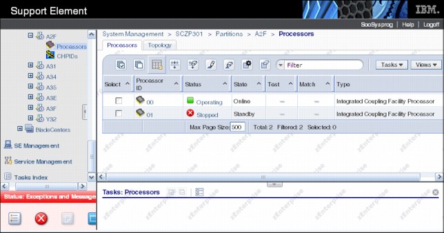
Figure 7-7 Example of the CF-CP Processor view from the SE with CP 01 stopped
The CP command is then used to bring an additional CP online, as shown in Figure 7-8.

Figure 7-8 Example of the Configure CP on command from the CF console
Figure 7-9 shows that both CPs are shown as Operating on the SE.

Figure 7-9 Example of the CF-CP Processor view from the SE with CP 01 operating
SHUTDOWN
The SHUTDOWN command ends CF operation, puts all CF logical central processors (CPs) into a disabled wait state, and then performs a System Reset for the CF LPAR, but only if no structures are present in the CF.
Figure 7-10 shows the confirmation panel after the command has been entered.
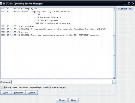
Figure 7-10 Example of the shutdown command from the CF console
|
Note: If structures are present in the CF, the shutdown operation is canceled and the CF continues operating. This is a safer way to shut down a CF than using the Deactivate task on the HMC. Even though the operator is warned that doing a Deactivate could be disruptive, the same message is issued regardless of whether the CF contains structures or not. If the operator replies to proceed with the deactivation, the CF will be deactivated, regardless of whether it contains structures or not.
If the SHUTDOWN completed successfully for the CF, there will be no need to then perform a DEACTIVATE for the CF.
In the case where a SHUTDOWN cannot be completed successfully (for the last CF in the sysplex, for example), the HMC DEACTIVATE function must be used.
|
7.4 Hardware Management Console and Support Element tasks
The Hardware Management Console (HMC) and Support Element (SE) provide link information from a hardware point of view. All panels discussed here are based on a z196 with the HMC and the SE running the code level shown in Figure 7-11 on page 212.
|
Important: The information in this section is relevant to both z196 and zEC12 CPCs. However, on zEC12 and later, you can use the D CF command to obtain information that was previously only available on the HMC or SE. If your system is running on a zEC12 or later, check if the D CF command will provide the information you require before using the SE.
|
Figure 7-11 System information
For all the examples, we were logged on in SYSPROG mode (User role) and we used the Tree-Style User Interface (UI).
The HMC and SE can also be set to the User Interface style called Classic User Interface. This is the well-known style used by IBM for a long time but the default style was recently set to the Tree-Style User Interface because it allows more flexibility and is easy to use. For details about both UI styles or how to change the UI style, see System z Hardware Management Console Operations Guide, SC28-6905.
The panels might differ when viewing another processor generation or LIC level. However, the basic information and data that can be gathered should be the same.
|
Note: Channels can be displayed on the SE by selecting the processor or an image. The key difference is that the PCHID or physical link status is shown when selecting the processor perspective, whereas the logical channel or link status is shown if you select the image perspective.
|
The following functions are explained in this section:
The Display Adapter ID panel shows the correlation between the physical adapter location and the assigned AID.
Displaying the status of a CIB link provides information about the status, type of link, logical channel, CHPID characteristic, AID and port number, all owning images, hardware location, and the swapped status from the processor point of view.
Displaying the status of a logical CIB link provides information about the status, type of link, PCHID, CHPID characteristic, AID and port number, owning images, hardware location, and the swapped status from the image point of view.
The View Port Parameters panel shows information such as Link Width, bandwidth, and the Port state about a coupling link.
The Channel Problem Determination function provides access to several selections. One of these in particular will be discussed in detail because it provides useful information:
The Analyze Channel Information panel shows information about a coupling link such as the Connection Type, Node Descriptor, the State and Status and several configuration details about the selected coupling link.
The System Activity Display provides information about the activity of the selected resources, which can be links, channels, or processors.
7.4.1 Display Adapter IDs
The Display Adapter ID panel can be accessed by performing the following steps:
1. Log on at the HMC (using SYSPROG authority).
2. Open Systems Management.
3. Open Servers.
4. Select the processor whose AIDs you want to look at (SCZP301, in our example).
5. Click Single Object Operation under the Recovery task list and confirm the selection in the new window that is brought up. You are now logged on to the Support Element.
6. Open System Management.
7. Open Server Name (SCZP301, in our example).
8. Open CPC Configuration in the Tasks area.
9. Click Display Adapter ID.
Figure 7-12 shows the Display Adapter ID panel from our z196. All installed fanouts are listed with their location code, the type of the fanout, and the assigned AID. Note, however, that this display does not differentiate between the different types of InfiniBand coupling fanouts.

Figure 7-12 Display Adapter ID
|
Note: All fanouts have an AID assigned but only PSIFB fanouts use them. The MBA and HCA-IO fanouts do not use an AID.
|
7.4.2 Determining the CHPIDs that are associated with an AID/port
If you are going to perform actions that result in an InfiniBand port going offline, you will need to identify all the CHPIDs and LPARs that might be affected by that action. There are two ways to get this information. One way is by using the SE, and the other is through HCD. However, because operators typically do not have access to HCD, we focus on the SE method here. There is no mechanism to display the AID/Port that is associated with a CHPID on z/OS, or to get a list by AID/Port on the HMC or SE. However, the AID/Port are assigned to a Cage/Slot/Jack in the CPC, and we can get a list of all the Vouched and CHPIDs that are associated with the Cage/Slot/Jack. To do this, perform the following steps:
1. Log on at the HMC (using SYSPROG authority).
2. Open Systems Management.
3. Open Servers.
4. Select the processor containing the AID/port that you will be working on (SCZP301, in our example).
5. Click Single Object Operation under the Recovery task list and confirm the selection in the new window that is brought up. You are now logged on to the Support Element.
6. Open System Management.
7. Expand the CPC (SCZP301, in our example).
8. Click Channels.
A list of all the channels on the CPC will be presented, sorted by the PCHID/VCHID value. Scroll through the list until you find one of the VCHIDs that you know will be impacted by the change. In this example, we will assume that VCHID 73B is assigned to the port that is being changed.
In the list shown in Figure 7-13, notice that VCHID 073B is assigned to CHPID AE in CSS 2, and that CHPID is assigned to a port that resides at Cage-Slot-Jack A25B-D215-J01.

Figure 7-13 SE Channel list
To determine which other CHPIDs are assigned to the same port, note that location and then sort the Cage-Slot-Jack column by clicking the up-arrow in that column heading. Scroll down to the Cage-Slot-Jack that you noted. An example is shown in Figure 7-14.

Figure 7-14 Sorted channel list
You can see that CHPIDs AE, 98, 97, and 96, all in CSS 2, are assigned to that port. Using the CSS and CHPIDs information, it should be possible to identify all the LPARs on that CPC that will be affected by any change to that port. Follow the same process to identify the CHPIDs (and therefore, the LPARs) that are assigned to the port on the other end of the link.
7.4.3 Toggling a CHPID on or offline using HMC
As discussed in “Considerations for configuring CHPIDs offline from HMC” on page 201, it is generally preferable for CHPIDs to be configured online or offline from the operating systems that are using them, rather than from the HMC. However, there might be situations where you need to perform this action from the HMC, so we illustrate here how to do this.
|
Important: When performing a toggle action, you must select the LPAR where you want the change to take effect. For example, if LPARs A21 and A22 are using CHPID 93 in CSS 2, and you attempt to perform the toggle action after selecting both LPARs, you will be presented with a panel indicating that the action can only be performed against one LPAR, and asking you to select which of the two LPARs you want to perform the action against.
|
1. Log on to the HMC (using SYSPROG authority).
2. Open Systems Management.
3. Open Servers.
4. Select the processor whose CHPID status you want to change (SCZP301, in our example).
5. Select the LPAR or LPARs that uses the CHPID that you want to change.
6. Expand the Operational Customization option.

Figure 7-15 Toggling a CHPID offline using the HMC
8. You are presented with a list of the CHPIDs that are available to the selected LPAR, and the status of each CHPID. This is shown in Figure 7-16.

Figure 7-16 List of CHPIDs available for toggle action
9. Select the CHPIDs that you want to toggle offline. In this example, we select CHPID 93.
10. To change the state of the selected CHPID from offline to online, or online to offline, click the Toggle button at the bottom of the window, as shown in Figure 7-17.

Figure 7-17 Toggling a CHPID offline
11. After you press Toggle, the desired state of the CHPID will change to Standby. However, the action to configure the CHPID offline has not started yet. If you prefer, you can clear the CHPID, or select additional CHPIDs.
12. When you are ready to implement the change, click the Apply button.
13. When the status change completes, you are presented with a status panel as shown in Figure 7-18.

Figure 7-18 Result of toggle action
|
Note: If you have a valid reason for toggling the CHPID offline to several LPARs simultaneously, you can do that from the SE.
Select the CHPIDs that you want to toggle from the channel list and select the Configure On/Off option under Channel Operations. If the CHPID is in use by multiple LPARs, you will be asked to select which LPARs you want to be affected by the toggle action.
|
7.4.4 Displaying the status of a CIB link (CPC view)
|
Tip: On a zEC12 or later, much of the information that you can obtain about a CIB CHPID from the SE can also be obtained using the z/OS D CF or D M=CHP(xx) command.
|
The channel and link work area can be opened by performing the following steps:
1. Log on at the HMC (using SYSPROG authority).
2. Open Systems Management.
3. Open Servers.
4. Select the processor whose CHPID status you want to look at (SCZP301, in our example).
5. Click Single Object Operation under the Recovery task list and confirm the selection in the new window that is brought up. You are now logged on to the Support Element.
6. Open System Management.
7. Open Server Name (SCZP301, in our example).
8. Click Channels.
Figure 7-19 on page 220 shows the channel status of a processor called SCZP301. This panel shows the following information for each defined channel:
– Channel ID (PCHID or VCHID number)
|
Note: A PCHID in the range from 0700 to 07FF lacks the exact one-to-one relationship between the identifier and the physical location. For more information see 2.4.2, “VCHID - Virtual Channel Identifier” on page 28.
|
– Logical channel, consisting of channel subsystem ID (CSS ID) and CHPID
– Channel status and State (physical link status)
– The hardware location of the channel consisting of the Cage, Slot, and Jack
– Type (Coupling over InfiniBand, in our case)

Figure 7-19 Status of CIB links (processor view)
|
Tip: All parts of the window and the table can be readjusted in size to provide more flexibility in viewing specific information.
|
For a better understanding of how changes in z/OS and the CF are reflected on the SE, try the following actions on a test sysplex after making sure that more than one link is available and check the SE changes for both ends of the link after each one:
– Configure a shared CHPID offline in one of the sharing z/OS systems.
– Configure that CHPID offline in all the other systems that are sharing it.
– Configure a CHPID offline from the CF console.
9. To get additional information, click the Channel ID (PCHID or VCHID) you want to look at. A detailed coupling link status is shown in Figure 7-20 on page 221.
From this panel you can see the following information:
•Channel status
•Type (Coupling over InfiniBand, in our case)
•Logical channels, consisting of CSS ID and CHPID
•CHPID characteristic
•Adapter ID and port number
•The LPARs in the CHPID’s access list
•The hardware location of the channel consisting of Cage, Slot, and Jack
•Swapped status

Figure 7-20 PSIFB coupling link details: Processor view
|
Tip: You can go directly to Channel Problem Determination from here. This option is described in 7.4.7, “Useful information from the Channel Problem Determination display” on page 224.
|
7.4.5 Display the status of a logical CIB link (Image view)
|
Tip: On a zEC12 or later, much of the information that you can obtain about a CIB CHPID from the SE can also be obtained using the z/OS D CF or D M=CHP(xx) command.
|
You can open the CHPID work area by following these steps:
1. Log on at the HMC (using SYSPROG authority).
2. Open Systems Management.
3. Open Servers.
4. Select the processor whose CHPID status you want to look at (SCZP301, in our example).
5. Click Single Object Operation under the Recovery task list and confirm the selection in the new window that is brought up. You are now logged on to the Support Element.
6. Open System Management.
7. Open Server Name (SCZP301, in our example).
8. Open Partitions.
9. Open Partition Name (A2F, in our example).
10. Click CHPIDs.
Figure 7-21 on page 222 shows the CHPID status of an image called A2F. This panel shows the following information for each channel defined for this specific LPAR:
– Logical channel, consisting of CSS ID and CHPID
– PCHID (or VCHID number)
|
Note: A PCHID in the range from 0700 to 07FF lacks the exact one-to-one relationship between the identifier and the physical location. For more information see 2.4.2, “VCHID - Virtual Channel Identifier” on page 28.
|
– Channel status and State (logical link status specific to this LPAR)
|
Important: When looking at a shared coupling link from two logical partitions (Image view), the coupling link (CHPID) might have a different status for each. It is essential to select the CHPID through the desired logical partition from which you want to view.
|
– CHPID characteristic
– Type (that is, Coupling over InfiniBand)

Figure 7-21 Status of logical CIB link (Image view)
11. To get additional information, click the logical channel number that you want to look at. A detailed coupling link status is shown in Figure 7-22 on page 223. This is similar, but not identical to, the display that is shown in Figure 7-20 on page 221.
This panel shows the following information:
•Channel status
•Type (Coupling over InfiniBand, in our case)
•PCHID (or VCHID)
•CHPID characteristic
•Adapter ID and port number
•Owning Image and all owning images
•The hardware location of the channel consisting of Cage, Slot, and Jack
•Swapped status

Figure 7-22 PSIFB coupling link details: Logical partition view
7.4.6 View Port Parameters panel
You can open the View Port Parameters panel by following these steps:
1. Log on at the HMC (using SYSPROG authority).
2. Open Systems Management.
3. Open Servers.
4. Select the processor whose CHPID status you want to look at (SCZP301, in our example).
5. Click Single Object Operation under the Recovery task list and confirm the selection in the new window that is brought up. You are now logged on to the Service Element.
6. Open System Management.
7. Open Server Name (SCZP301, in our example).
8. Click Channels.
9. Select the coupling link you want to view the port parameters (CHPID 2.80, in our example).
10. Now the PSIFB coupling link details panel is shown. Click Advanced Facilities.
11. In the new Advanced Facilities panel, click Card Specific Advanced Facilities.
12. Another Advanced Facilities panel is loaded. Click View Port Parameters here.
Figure 7-23 shows the View Port Parameters panel. The panel shows the Link Width, the bandwidth, and the Port State for the selected PSIFB coupling link.

Figure 7-23 View port parameters
This panel helps you determine the physical status of the link for link problem determination. Further, it provides information about the current Link width. For example, in case of a problem with a 12x link, the Link width field could have values down to 8x, 4x, 2x, or 1x. The Port State shows whether the physical link is active or down.
|
Note: In the panel, the Link speed field actually reports the speed of each fibre pair in the link (for example, it could be 2.5 Gbps for a Single Data Rate link or 5.0 Gbps for a Double Data Rate link). To determine the full bandwidth of the link, multiply the value in the Link speed field by the number of lanes, as reported in the Link width field.
Thus, in this example, the design bandwidth of the link is 6 GBps (5.0 Gbps per lane times 12 lanes).
|
7.4.7 Useful information from the Channel Problem Determination display
You can open the Channel Problem Determination panel by following these steps:
1. Log on at the HMC (using SYSPROG authority).
2. Open Systems Management.
3. Open Servers.
4. Select the processor whose CHPID status you want to look at (SCZP301, in our example).
5. Click Single Object Operation under the Recovery task list and confirm the selection in the new window that is brought up. You are now logged on to the Service Element.
6. Open System Management.
7. Open Server Name (SCZP301, in our example).
8. Click Channels.
9. Select the coupling link you want to see detailed information about (CHPID 2.80, in our example).
10. Now the PSIFB coupling link details panel is shown. Click Channel Problem Determination.
11. In the Select Partition and CSS.CHPID panel, select the partition from where you want to look at the coupling link (in our example, we select partition A21).
On the Channel Problem Determination panel, there are several valid options to choose from for the selected coupling link; see Figure 7-24. We now discuss two of these options in more detail because they provide useful information about the status of the selected coupling link.

Figure 7-24 Channel Problem Determination
Analyze Channel Information option
The Analyze Channel Information option is shown in Figure 7-25.

Figure 7-25 Analyze Channel Information option
Here are the details for the information provided in Figure 7-25:
•Channel Type (Coupling over InfiniBand).
•Partition ID - Provides the Partition ID of the selected partition.
•MIF ID - Provides the MIF ID of the selected partition.
•Channel Mode - Shows whether the link is spanned, shared, or dedicated.
•CSS.CHPID - Shows the logical channel, consisting of CSS ID and CHPID.
•PCHID - Shows the currently selected PCHID.
•CPATH - Provides the CSS and CHPID of the CHPID at the other end of this link.
•CSYSTEM - Provides the system name of the processor at the other end of this link.
|
Note: The CPATH and the CSYSTEM must match the Tag value from the attached node.
|
•LSYSTEM - Provides the system name of the local system as defined in the HCD.
•State and Status (from the processor view).
Provides the state and status of the link as seen from the processor view.
•Image Channel State and Image Channel Status (from the image view).
Provides the state and status of the link as seen from the image view.
•Node Descriptor for the local system (on the left side of the display) and the connected system (on the right side of the display).
– Node type - Self means the shown Node Descriptor (ND) information is from the channel itself. Attached indicates the shown Node Descriptor (ND) information is from the attached node.
– Node status - Valid means that there has been a successful port login. Invalid means there has not been any port login. A node status Valid but not current means there has been a port login, but the link was dropped afterward.
– Type/Model - Provides the CPC type and model of the node.
– Plant - This is the plant of manufacture of the node.
– Sequence number - The serial number of the node.
– Tag - The Tag field represents the CSS/CHPID for System z processors. The first character of the Tag field represents the CSS. The last two digits represent the CHPID (the second digit showing a 0 is reserved).
Table 7-1 illustrates the CSS-to-Tag relation. Read the tag value in the top line and get the corresponding CSS IDs the link has been defined to. For instance, Tag = C080; C indicates the link is defined to CHPID 80 in CSS0 and CSS1.
Table 7-1 CSS-to-tag relationship
|
CSS/Tag
|
1
|
2
|
3
|
4
|
5
|
6
|
7
|
8
|
9
|
A
|
B
|
C
|
D
|
E
|
F
|
|
0
|
|
|
|
|
|
|
|
X
|
X
|
X
|
X
|
X
|
X
|
X
|
X
|
|
1
|
|
|
|
X
|
X
|
X
|
X
|
|
|
|
|
X
|
X
|
X
|
X
|
|
2
|
|
X
|
X
|
|
|
X
|
X
|
|
|
X
|
X
|
|
|
X
|
X
|
|
3
|
X
|
|
X
|
|
X
|
|
X
|
|
X
|
|
X
|
|
X
|
|
X
|
•Card Description (InfiniBand fanout card - optical).
•Connection Type (HCA2-O 12x IFB, in our example).
|
Note: At the time of writing, this panel is the only place where you can obtain information about the physical type (HCA1, HCA2, or HCA3, and 1X or 12X) and protocol (IFB or IFB3).
|
7.4.8 System Activity Display
This displays the system activity for CPCs or a group of CPCs. System activity includes the channel activity and physical processing activity that has been defined in the system activity profiles that are stored in the selected CPCs. For more information about assigning and customizing activity profiles, see System z Hardware Management Console Operations Guide, SC28-6905.
With the System Activity Display, you can create a list of links you want to monitor (that is, if a problem is suspected to be caused by one or more CIB links). Figure 7-26 on page 228 shows a System Activity Display customized for CHPIDs 2.8* on processor SCZP301 as an example. These are the CHPIDs that are in use by our CF, FACIL04.
Note that the utilization reported on the System Activity Display is the utilization of the CHPID, not the utilization of the bandwidth of the associated InfiniBand link.

Figure 7-26 System Activity Display for InfiniBand CHPIDs
7.5 PSIFB Channel problem determination
There can be situations where a channel is not working as expected. Reasons for this include the following possibilities:
•A CPC has been added or an existing CPC was upgraded
•A physical cable might be broken or damaged
•Hardware errors
•Network issues
•Configuration errors
This section describes the actions you can take to investigate the cause of the problems.
7.5.1 Checking that the link is physically working
The first step to take in your investigation is to determine whether the physical link is working. See 7.4.4, “Displaying the status of a CIB link (CPC view)” on page 219 for a description of how to display the physical link status of a PSIFB channel. If the channel is online to at least one LPAR, use the “Channel Problem Determination” button to display the PCHID details panel as shown in Figure 7-20 on page 221.
See 7.4.7, “Useful information from the Channel Problem Determination display” on page 224 for further details about the configuration from the perspective of the selected LPAR.
Additionally, the “View Port Parameter” function, described in 7.4.6, “View Port Parameters panel” on page 223, is a useful place to determine whether the link is running at the correct speed. These three points are the basics from the hardware perspective.
7.5.2 Verifying that the physical connections match the IOCDS definitions
A useful way to determine whether the current IOCDS accurately reflects how the adapters and ports are connected to each other is to display the IOCDS CIB channel information about the SE using the Input/Output (I/O) Configuration task, and then to compare that information to the physical cabling and connections.
The following example displays the IOCDS information for both ends of a defined CIB coupling channel link. In this example, we were logged on in SYSPROG mode (User role) and we used the Tree-Style User Interface (UI).
1. Log on to the HMC (using SYSPROG authority), and then open Systems Management.
2. Open Servers.
3. Select the CPC whose IOCDS you want to look at (SCZP201, in our example).
4. Click Single Object Operation under the Recovery task list and confirm the selection in the window that is brought up. You are now logged on to the Support Element.
5. Open System Management.
6. Open Server Name (SCZP201, in our example).
7. Open CPC Configuration in the Tasks area.
8. Click Input/output (I/O) Configuration.
9. Select the active IOCDS and click View on the taskbar and then click Channel Path Configuration.
10. In the Channel Path Configuration click the CHPID you want to look at (0.93 in our example), select View on the taskbar, and then click CHPID Information.
Figure 7-27 shows the CHPID Information for CHPID 0.93. In our IOCDS A0, the AID 09, Port 2 is linked to CHPID 2.85 on the SCZP301 CPC.

Figure 7-27 CHPID Information from the Input/output (I/O) Configuration for System SCZP201
Next, we followed the same steps for the system at the other end of the link, SCZP301. Figure 7-28 shows the result for that system. In IOCDS A0 on that CPC, AID 0A, Port 1 is connected to CHPID 0.93 on the SCZP201 CPC.
Use this information to verify that the actual cabling matches the definitions. Note that, unlike FICON channels, there is no way on the SE to view the actual connection information, so this checking must be carried out physically.

Figure 7-28 CHPID Information from the Input/output (I/O) Configuration for System SCZP301
7.5.3 Setting a coupling link online
A coupling link should be set online from the CF LPAR first, and then from the z/OS LPAR. The management of the coupling link for the CF LPAR is normally handled from the Operating System Console on the HMC or SE.
Although a coupling CHPID can be toggled offline using the Configure Channel Path On/Off selection on the HMC or SE, the CF console must be used to bring the CHPID online to the CF.
If you are unable to configure online a correctly defined coupling link, use the following checklist to check the status and attempt to resolve the error:
1. Make sure that the CF LPAR is activated.
You can obtain the status of the CF LPAR by using the LPAR operating view on the HMC/SE panels, as shown in Figure 7-15 on page 216.
2. Make sure that the z/OS LPAR is activated.
You can obtain the status of the z/OS LPAR by using the LPAR operating view on the HMC/SE panels, as shown in Figure 7-15 on page 216.
3. Check the physical coupling link status.
Use the procedure described in 7.5.1, “Checking that the link is physically working” on page 228 to determine whether the link is working correctly; if the link is working correctly, then proceed to the next step.
If the link is not working correctly, follow your normal installation procedures for addressing coupling link problems.
4. Check the logical coupling link status.
The logical status of the coupling link is determined by using the z/OS and CF consoles.
a. Check the CHPID status on the CF by issuing the following command on the CF console:
DISPLAY CHP ALL
|
Note: If the z/OS LPAR is not activated, the channel status of “Online/Loss of Signal” or “Online / Sequence Timeout” is a normal status.
|
b. Next, display the CHPID status on z/OS, using the following command:
D M=CHP(xx)
In the output from this command, check the LOGICAL column near the start of the output. The LOGICAL status should be ONLINE.
If it is OFFLINE, use a VARY PATH command to bring it logically online.
c. On the SE where the z/OS LPAR resides, obtain the status from the associated CHPIDs, as explained in 7.4.4, “Displaying the status of a CIB link (CPC view)” on page 219.
|
Note: If the CHPID is only online on the z/OS LPAR, then configure it off first using the procedure from the HMC, as described in 7.4.3, “Toggling a CHPID on or offline using HMC” on page 216.
|
5. Configure the channel on from the CF LPAR side.
On the Operating System Console for the CF LPAR on the HMC, use the following command:
CON xx,ONLINE
6. Configure the channel on from the z/OS LPAR side.
Use the following MVS command to configure the link online:
CF CHP(xx),ONLINE
If the D CF command indicated that the logical status of the CHPID was OFFLINE, use the following command to bring the path logically online:
V PATH(cfname,xx),ONLINE
7. The coupling link should now be online.
7.6 Environmental Record Editing and Printing
When an error occurs, the system records information about the error in the Logrec data set or the Logrec log stream. The information provides you with a history of all hardware failures, selected software errors, and selected system conditions.
Use the Environmental Record Editing and Printing (EREP) program to print reports about the system records to determine the history of the system, or to learn about a particular error.
For further information, refer to z/OS MVS Diagnosis: Tools and Service Aids, GA22-7589.
1 Configuring a shared CHPID offline to a z/OS system using the MVS CONFIG command, or deactivating an LPAR that is using a particular CHPID does not impact STP’s ability to use that CHPID for timing signals. The CHPID will only become inaccessible to STP if it is configured offline in all sharing LPARs.
..................Content has been hidden....................
You can't read the all page of ebook, please click here login for view all page.