

Migration planning
The migration from earlier sysplex connectivity solutions to InfiniBand connectivity options provides you with the opportunity to completely refresh your coupling infrastructure, resulting in improved availability, flexibility, and performance. However, because it involves the eventual replacement of all your existing coupling links, you must plan the migration carefully, especially if you need to complete the migration without impacting application availability.
It is safe to say that every enterprise’s sysplex environment is unique. It might range from a small 1-CPC sysplex in a single computer room to a large n-way sysplex using structure duplexing technology spread over many kilometers. Some enterprises are able to schedule a window to perform a disruptive migration; others need to perform the migration without any outage to their core applications.
This chapter describes several of the most common migration scenarios. They have been tested and documented to help you plan your specific migration. All scenarios focus on the basic steps to successfully complete the migration. You will need to adapt each scenario to your specific installation, depending on the number of coupling links, Coupling Facility CPCs, involved logical partitions, and number of System z servers in your configuration.
The following topics and scenarios are presented in this chapter:
•Migration considerations
•Connectivity considerations
•Introduction to the scenario notation
•Scenario 1: Disruptive CPC upgrade, PSIFB already in use (ICFs)
•Scenario 2: Migration to PSIFB with no POR (ICFs)
•Scenario 3: Concurrent CPC and link upgrade
•Scenario 4: Concurrent PSIFB implementation (stand-alone CFs)
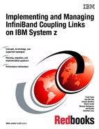
•Scenario 5: Concurrent migration from IFB to IFB3 mode
•Scenario 6: Concurrent switch between IFB modes
4.1 Migration considerations
You must carefully plan for the migration to PSIFB coupling links. Introducing PSIFB links into an existing environment requires a thorough understanding of the different System z CPC implementations of Coupling Facility technology. When implementing a new CPC (like a z196 and z114) you need to consider migration to InfiniBand as part of the overall migration plan. A conservative approach aimed at providing easy fallback and minimizing application disruption is likely to consist of multiple steps.
We assume that you have familiarized yourself with the technical aspects of InfiniBand technology on IBM zEnterprise and System z servers as described in Chapter 2, “InfiniBand technical description” on page 17. Further, we assume that you have finished the planning for the implementation of the InfiniBand technology in your specific environment by taking into account all considerations listed in Chapter 3, “Preinstallation planning” on page 37.
This chapter focuses on the actual implementation steps, providing sample step-by-step guidance for each of the most common implementation scenarios. Table 4-1 contains a list of the scenarios discussed in this chapter.
Table 4-1 Sample migration scenarios
|
Section
|
Description
|
Page
|
|
4.3
|
Scenario 1 - Disruptive CPC upgrade, PSIFB already in use (ICFs)
|
|
|
4.4
|
Scenario 2 - Migration to PSIFB with no POR (ICFs)
|
|
|
4.5
|
Scenario 3 - Concurrent CPC and link upgrade
|
|
|
4.6
|
Scenario 4 - Concurrent PSIFB implementation (stand-alone CFs)
|
|
|
4.7
|
Scenario 5 - Concurrent migration from IFB to IFB3 mode
|
|
|
4.8
|
Concurrent switch between IFB modes
|
Depending on your environment and migration goals, you might need to use several of the migration scenarios, one after the other. The following example shows how you might need to combine a number of scenarios to get from where you are now to where you want to end up.
Example implementation steps
The sysplex environment consists of several System z10 CPCs, currently connected using ICB4 links. Your company has decided to upgrade to the latest generation of zEnterprise servers, and you are responsible for ensuring that the migration is carried out with no application outages. In this case, you need to use several of the sample scenarios.
•First, you need to add the InfiniBand adapters to your existing System z10 CPCs; see 4.4, “Scenario 2” on page 76, “Migration to PSIFB with no POR (ICFs)”.
•Next, you need to upgrade the z10s to z196s. There are a number of options for that migration:
– 4.3, “Scenario 1” on page 68, “Disruptive CPC upgrade, PSIFB already in use (ICFs)”
– 4.6, “Scenario 4” on page 95, “Concurrent PSIFB implementation (stand-alone CFs)”, depending on your configuration.
•Finally, you want to achieve the performance benefits of IFB3 mode, and this will involve replacing your HCA2-O adapters with HCA3-O adapters. 4.7, “Scenario 5” on page 108, “Concurrent migration from IFB to IFB3 mode” provides an example of how such a migration can be completed without impacting application availability.
Although this multistep process might seem complex, it can help you progress through a number of technology changes without impacting your application availability (depending on which migration option you select). Alternatively, if you are able to plan for an application outage, it might be possible to consolidate a number of changes into a single outage, thereby reducing the total number of steps that are required.
4.1.1 Connectivity considerations
In the migration scenarios we sometimes connect one version of an HCA adapter (HCA2, for example) to a different version (HCA3). The ability to mix and match adapters like this depends on the CPC generations that are to be connected. For example, a z10 with an HCA2-O fanout can be connected to a zEC12 with HCA3-O fanout; however, the link will run in IFB mode rather than in IFB3 mode.
Table 4-2 lists which 12X InfiniBand HCA fanouts can be interconnected, along with specific considerations.
Table 4-2 12X connectivity options
|
Server
(Link type)1
|
z9
(HCA1-O)
|
z10
(HCA2-O)
|
zEC12/zBC12
z196/z114 (HCA2-O)
|
zEC12/zBC12
z196/z114
(HCA3-O)b
|
|
z9
(HCA1-O)
|
NO
|
YES
|
YES
|
NO
|
|
z10
(HCA2-O)
|
YES
|
YES
|
YES
|
YES
|
|
zEC12/zBC12
z196/z114
(HCA2-O)
|
YES
|
YES
|
YES
|
YES
|
|
zEC12/zBC12
z196/z114
(HCA3-O)2
|
NO
|
YES
|
YES
|
YES
|
1 Refer to 2.2, “InfiniBand fanouts” on page 19 and 2.5, “InfiniBand coupling links” on page 30 for further detail regarding HCA fanouts.
2 HCA3-O fanouts support two modes, IFB and IFB3. The improved 12X IFB3 mode can only be used if the link is implemented between two HCA3-O fanouts and a maximum of four CHPIDs are defined to the HCA3-O ports at each end of the link.
Table 4-3 provides similar information for the 1X InfiniBand fanouts.
Table 4-3 1X connectivity options
|
Server
(Link type)1
|
z9
(N/A)2
|
z10
(HCA2-O LR)
|
zEC12/zBC12
z196/z114
(HCA2-O LR)3
|
zEC12/zBC12
z196/z114
(HCA3-O LR)
|
|
z9
(N/A)b
|
N/A
|
N/A
|
N/A
|
N/A
|
|
z10
(HCA2-O LR)
|
N/A
|
YES
|
YES
|
YES
|
|
zEC12/zBC12
z196/z114
(HCA2-O LR)c
|
N/A
|
YES
|
YES
|
YES
|
|
zEC12/zBC12
z196/z114
(HCA3-O LR)
|
N/A
|
YES
|
YES
|
YES
|
1 Subchannels and link buffers need to be considered during the migration phase; see Appendix C, “Link buffers and subchannels” on page 247.
2 Long-reach HCA fanouts are not supported on System z9.
3 HCA2-O LR adapters are still available for z10, but they have been withdrawn from marketing for z196 and z114. On z196 and z114, the replacement is HCA3-O LR. However, you still might have HCA2-O LR HCAs on a z196 if they were carried forward during a CPC upgrade.
4.2 Introduction to the scenario notation
To make it easier to understand and compare the various scenarios, we present each one using the same structure. After a brief description of the scenario, a diagram of the starting configuration is presented. The target configuration of each scenario is also shown in a diagram, typically at the end of the steps in the scenario. Depending on the complexity of the scenario, intermediate configurations might be shown as well.
The descriptions refrain from using actual PCHID or CHPID numbers because they will be different for each client. Instead, the relevant links are numbered and referred to accordingly, where necessary.
|
Note: To avoid making the scenarios overly complex, the number of links used in each scenario (and shown in the diagrams) represent the minimum number of links that are recommended to avoid any single point of failure.
If you use more than the minimum number of links, the scenario steps will be still the same with the exception that steps that deal with managing the links themselves will have to be repeated based on the number of links actually in use.
|
Different kinds of coupling link types are used in each scenario. For the legacy links we might have ISC3 links, ICB4 links, or a mixture of both link types. The links will be updated to the most appropriate PSIFB link types; for example, an ISC3 link is replaced by a 1x PSIFB link and an ICB4 link is replaced by a 12x PSIFB link. However, the handling of the various link types is identical, so the link type used in each scenario can be replaced to suit your configuration.
Table 4-4 lists the systems used in our examples. Note that the CPC name-to-CPC relationship might change in a scenario where the current CPC is going to be replaced by another one.
Table 4-4 CPCs used in migration scenarios
|
CPC
|
Model
|
CPC name 1
|
LPAR types
|
|
System z10 EC
|
E26
|
CPC1
|
z/OS
|
|
|
|
|
CF
|
|
System z10 EC
|
E40
|
CPC2
|
z/OS
|
|
|
|
|
CF
|
|
System z9 EC
|
S18
|
CPC3
|
z/OS
|
|
|
|
|
CF
|
|
zEnterprise 196
|
M32
|
CPC4
|
z/OS
|
|
|
|
|
CF
|
|
zEnterprise 196
|
M32
|
CPC5
|
z/OS
|
|
|
|
|
CF
|
|
System z10 EC
|
E26
|
CF01
|
CF only
|
|
System z10 EC
|
E26
|
CF02
|
CF only
|
1 CPC name that is specified for the CPC ID in the IOCDS.
The LPARs and their associated names from Table 4-5 are used in our examples. Depending on the scenario, the LPARs might reside in the same or in different CPCs.
Table 4-5 LPARs used in migration scenarios
|
LPAR Type
|
Name
|
|
z/OS
|
ZOS1, ZOS2
|
|
CF
|
CF1, CF2, CF3, CF4
|
Disruptive versus concurrent migrations scenarios
Whenever we describe a migration scenario as “concurrent”, we mean that it is required that all z/OS LPARs on the involved CPCs (and therefore all core applications) continue to be available throughout the migration. In these scenarios we assume that it is acceptable to move coupling structures between CF LPARs and also to deactivate a CF LPAR as long as at least one CF LPAR remains connected to all systems in the sysplex.
Note that if your critical applications exploit sysplex data sharing and dynamic workload routing, you have greater flexibility because the availability of your critical application is no longer tied to the availability of particular z/OS LPARs. This means that you can use a scenario that we describe as disruptive but without impacting your application availability.
If all involved CPCs, and therefore all z/OS LPARs and all applications, need to be shut down, the scenario is considered to be disruptive. Also, if the core applications are not configured for sysplex-wide data sharing, this also means that the scenario needs to be considered disruptive.
The terms “disruptive” and “concurrent” can be interpreted differently by one enterprise than by another. There is no absolute definition possible, because you might consider a given scenario to be disruptive, but it might be considered concurrent by someone else. Therefore it is important that you define your migration objectives as clearly as possible to be able to match them to one of our migration scenarios.
|
Note: The scenarios in this document reflect the current best practice guidance for CF outages as described in the white paper titled Best Practices: Upgrading a Coupling Facility, which is available at the following website:
|
|
Tip: Regardless of which scenario applies to your situation, at the start of the migration it is useful to clearly map which LPAR and CPC is connected to every coupling CHPID in each LPAR, for CF and z/OS LPARs.
Also, if the migration will consist of a number of configuration changes, document the expected configuration at the start of each step. This might take a little time, but it will prove invaluable in helping avoid human error (and potential outages) by configuring the wrong CHPID on or offline.
|
4.3 Scenario 1
Disruptive CPC upgrade, PSIFB already in use (ICFs)
There are two servers installed at the start of this scenario: a z9 EC and a z10 EC. Both CPCs already have InfiniBand fanouts installed and are connected with 12x PSIFB links. The z9 EC is going to be upgraded to a z196 server. Two LPARs, ZOS1 and CF1, are in use and reside in the z9 EC. Two more LPARs, ZOS2 and CF2, reside in the z10 EC. Figure 4-1 on page 69 shows the configuration at the start of the project.
In this case, the installation has already planned for a complete outage to allow for an upgrade to the computer room environment (for recabling and power maintenance), so they are going to take the opportunity of the outage to upgrade the z9. Because both CPCs will be down, this is considered to be a disruptive scenario where all LPARs on both CPCs are being stopped. However, if the installation prefers, it is possible to complete this migration without impacting the systems on the z10; that type of migration is described in 4.5, “Scenario 3” on page 86.

Figure 4-1 Scenario 1: Starting configuration
In this scenario, the z9 system uses HCA1-O fanouts for the PSIFB coupling connections. The z10 system has HCA2-O fanouts installed. The upgrade of the z9 is done as a “frame roll MES”, which means that the actual frames of the z9 will be replaced with the new frames of the z196, but the serial number will stay the same. Due to the nature of a frame roll MES, the CPC that is being upgraded will always have to be shut down.
In a frame roll MES, several I/O cards or fanouts might be transferred to the new frame. However, in this specific case, no InfiniBand fanouts are carried forward because the z196 does not support the HCA1-O fanouts. Therefore, new HCA fanouts are ordered. To be better positioned for future upgrades, order new HCA3 fanouts for the z196 because they are not only compatible with the HCA2 fanouts in the z10, but will also allow utilization of the improved IFB3 mode when the client upgrades their z10 CPC to a z196 in the future.
|
Note: The process described here, and in subsequent scenarios, might seem intricate. However, the objective is to shut down everything in an orderly manner, ensuring that the subsequent restart will be clean and will complete in a timely manner.
In this first scenario, we include steps that are not strictly necessary if one or both CPCs are going to be powered-down. However, we included the steps in an effort to have more consistency between the various scenarios presented in this chapter.
|
Following are the steps in this migration:
1. Update hardware configuration definition (HCD) for the new z196 and create the z196 IOCDS.
The new IOCDS for the z196 is generated and saved to the z9. The IOCDS will be carried forward during the upgrade to the z196 by the System Service Representative (SSR). This is the most convenient way to install an IOCDS on an upgraded CPC.
2. Write the changed IOCDS for the z10 EC.
Depending on the z196 definitions in HCD, the IOCDS for the z10 EC might need to be updated. If the LSYSTEM name of the z196 will be different than the LSYSTEM name of the z9, and/or the CHPID numbers for the HCA3 adapters in the z196 will be different than the corresponding numbers in the z9, then the z10 IOCDS will need to be updated.
If you use the same CHPIDs and CSSs on the new PSIFB links that you used before on the coupling links, and the same LSYSTEM name, then no IOCDS change is required in relation to the coupling links. For more information, see “LSYSTEM” on page 162.
3. The CFRM policy is updated.
Because the z9 EC is being upgraded to a z196, the CFRM policy needs to be updated. The changes that you need to make depend on whether you plan to use the same name for the z196 CF. The CPC serial number will remain the same because this is an upgrade MES, but the CPC type is going to change and that needs to be reflected in the CFRM policy as well.
The structure sizes have to be updated as well, because the new z196 will have a different Coupling Facility Control Code (CFCC) level than the z9. To determine the correct sizes, use either CFSizer or the Sizer tool available on the CFSizer site. An alternate process is described in the document titled “Determining Structure Size Impact of CF Level Changes”, available on the web at:
Save the updated policy with a new name, for example, “newpol”. This gives you the ability to fall back to the previous CFRM policy if problems are encountered.
Note that the new policy will not actually be activated until after the upgrade is complete.
4. Quiesce all work on all z/OS LPARs in preparation for stopping z/OS and powering down both CPCs.
5. Set the CF in the z9 EC into maintenance mode.
As the first step to emptying the CF1 CF on the z9 EC, set the CF into maintenance mode by using the following z/OS command:
SETXCF START,MAINTMODE,CFNM=CF1
6. Move CF structures from the CF in the z9 EC to the CF in the z10 EC.
|
Note: If you are running z/OS 1.12 or higher, verify that the reallocation will have the desired effect by using this command first:
D XCF,REALLOCATE,TEST
Address any problem that is detected before you reallocate the structures.
|
Reallocate the structures into the CF LPAR on the z10 EC using the following command:
SETXCF START,REALLOCATE
It is important that you empty the CF in the CPC that is being upgraded before you shut down the sysplex. If you do not do this, information about the structures in the z9 CF will be retained in the Coupling Facility Resource Management (CFRM) Couple Data Set and cannot be removed.
7. Check that all structures have been moved.
Determine if any structures have remained in the CF by using this command:
D XCF,CF,CFNAME=CF1
If any structure did not move, check whether application-specific protocols are needed and use these to move (or rebuild) the structure. Repeat this step until all structures have been moved.
|
Note: If you are running z/OS 1.12 or higher, review the reallocation report to determine why a structure was not moved by using this command:
D XCF,REALLOCATE,REPORT
If you have a z/OS 1.13 or higher system in the sysplex, you might find that system provides more helpful messages to explain why a structure is not being moved to the CF you expect.
|
For more information about moving structures out of a CF, refer to the sections titled “Removing structures from a coupling facility for shutdown” and “Removing a structure from a coupling facility” in z/OS MVS Setting Up a Sysplex, SA22-7625.
8. Set the z9 EC CF logically offline to all z/OS LPARs.
Placing CF1 in MAINTMODE and verifying that the REALLOCATE command was successful can ensure that no structures are left in CF1. However, to be sure that no active structures remain in the CF, it is prudent to take the CF logically offline to all connected z/OS systems before shutting it down.
This is achieved using the following command in each z/OS system:
V PATH(CF1,xx),OFFLINE (you will have to add the UNCOND option for the last CHPID)
This has the effect of stopping the issuing z/OS from being able to use the named CF. If this z/OS is still connected to any structure in the CF, the command will fail.
Note that this command does not make the named CHPIDs go offline; it is simply access to the CF that is removed. The CHPIDs will be taken offline later. If you issue a D CF,CFNM=CF1 command at this time, you will see that each CHPID still shows as being physically ONLINE, but logically OFFLINE.
|
Note: The paths to the CF can be brought logically back online by using the VARY PATH(cfname,chpid) command or by performing an IPL of the z/OS system.
|
9. Shut down CF1.
Next you need to deactivate the CF1 LPAR. If the CF is empty, use the SHUTDOWN command from the CF1 console on the HMC. The advantage of using a SHUTDOWN command, compared to deactivating the LPAR using the HMC DEACTIVATE function, is that the SHUTDOWN command will fail if the CF is not empty. The end result of the SHUTDOWN is effectively the same as the end result of performing a DEACTIVATE, so it is not necessary to perform a DEACTIVATE of a CF LPAR that was successfully shut down using the SHUTDOWN command.
If the CF still contains one or more structures, but the decision has been made that the instance of the structure does not need to be moved or recovered, the SHUTDOWN command will not complete successfully, so DEACTIVATE the CF LPAR instead.
10. Stop ZOS1 and deactivate the ZOS1 LPAR.
The z/OS LPAR on the z9 is now shut down (using V XCF,sysname,OFFLINE). When that system has entered a wait state, the LPAR should be is deactivated.
All LPARs on the z9 should now be in a state that is ready for the CPC to be powered down.
11. STP-related preparation.
Note the current STP definitions and the STP roles (CTS, PTS, BTS, and Arbiter) before any changes are made, so they can be reinstated later.
For more details refer to the Redbooks document Server Time Protocol Recovery Guide, SG24-7380, and the white paper Important Considerations for STP and Planned Disruptive Actions, available on the web at:
To better protect a sysplex against potential operational problems, STP was changed so that it prevents the shutdown of a zEnterprise or System z10 CPC that has any STP role assigned. This change is documented in the white paper Important Considerations for STP server role assignments, available on the web at:
As a result of this change, you need to remove the STP server roles in the STP configuration panel before the CPCs are shut down. Remove the Arbiter role first (not applicable in this scenario) and then the BTS role1.
To implement the role changes, check the setting of the option called “Only allow the server(s) specified above to be in the CTN”2 in the STP network configuration tab on the HMC:
– If this option is currently selected:
• It must be cleared so that the BTS role can be removed from the z9 (because no server role assignment changes can be made if this option is enabled).
• Remove the BTS role from the z9.
– If this option is not selected:
• Remove the BTS role from the z9.
Note the original setting of this option because it is required in step 21.
|
Note: Remove the STP server roles only if the complete CTN will be shut down. If your CTN contains other CPCs that will continue to work, the STP server roles need to be reassigned to the still-active CPCs.
|
When the z9 is upgraded to a z196, the STP definitions on that CPC will need to be updated to specify the name of the CTN that the CPC is to join. If you remove the z9 from the CTN prior to powering it down, you will be able to configure offline all coupling links between the two CPCs because they are no longer being used by STP.
To remove the z9 from the CTN, logon to the z9 SE, go into the System (Sysplex) Time option, select the STP Configuration tab and blank out the Coordinated timing network ID field.
Finally, select the “Only allow the server(s) specified above to be in the CTN” option on the HMC so that after the POR, the CTN configuration will be remembered.
12. Configure offline all paths to the z9 EC CPC.
When all LPARs on the z9 EC are down, configure offline all coupling links to that CPC. To do this, issue the following command for each CHPID going to CF1, for each z/OS LPAR that is communicating with CF1:
CONFIG CHP(xx),OFFLINE
Because the CF1 LPAR is down at this point, it should not be necessary to use the CONFIG CHP(xx),OFFLINE,UNCOND command for the last CHPID from each z/OS LPAR to CF1.
Note that each z/OS LPAR might use different CHPIDs to connect to CF1, so ensure that you configure the appropriate CHPIDs for each LPAR (in our example, there is only one z/OS at this point, ZOS2).
After issuing all the CONFIG CHP commands, issue a D CF,CFNM=CF1 command from each connected z/OS to ensure that all the CHPIDs to that CF are now both logically and physically offline to that LPAR.
When the CONFIG OFFLINE command is issued for a z/OS CHPID, the z/OS end of the link will be taken offline; however, the CF end will remain online. In this example, that is not an issue because the CPC containing CF1 is going to be replaced.
If there are any CF-to-CF links between CF2 and CF1, issue the following command on CF2 to take those CHPIDs offline:
CON xx OFF
Finally, use the z10 SE to check if there are any remaining coupling links online to the z9. Toggle offline any such VCHIDs or PCHIDs at this point, using the HMC.
13. Shut down z/OS LPARs on z10.
The next step is to prepare the z10 for power-down to enable the computer room maintenance.
Use your normal procedures to shut down the z/OS LPARs on the z10 (in our example, ZOS2). After the z/OS systems have been stopped, deactivate those LPARs.
14. Deactivate the CF2 CF LPAR.
Prior to stopping the CF1 CF, any structures in that CF were moved to the CF2 CF. When the z/OS LPARs are shut down, various structures will remain in the CF2 CF. For that reason, the CF SHUTDOWN command will fail. Therefore, simply deactivate the CF2 LPAR.
15. Power down the CPCs.
Power down the z9 now.
Then power down the z10 EC.
16. The SSR starts the upgrade of the z9 EC.
17. The z10 is powered on and activated with the updated IOCDS (if an IOCDS update was necessary); however, no LPARs are activated yet.
Note that if the IOCDS was updated as part of the z9 upgrade, then all CHPIDs will be online at the end of the activation. However, if the IOCDS was not updated, then any CHPIDs that were taken offline as part of the shutdown will be offline after the activation completes.
18. After the SSR is finished with the z9 upgrade, the z196 is powered on and activated with the new IOCDS3. Again, no LPARs should be activated yet.
19. Ensure that there is an available timing link between the z10 and the z196.
Use the z10 SE to ensure there is at least one coupling CHPID online from the z10 to the z196 so that STP can exchange time signals between the two CPCs.
20. Add CTN ID to the z196.
In this step and the next one, we make changes to the STP configuration, so disable the “Only allow the server(s) specified above to be in the CTN” option on the z10 HMC before proceeding.
Because the z196 is considered to be a new CPC by STP, you must log on to the z196 HMC, select the System (Sysplex) Time option, and enter the CTN ID on the STP Configuration tab.
After the CTN ID of the z196 has been added, use the STP panels on the z10 and z196 to ensure that the change was successful and that both CPCs are now in the CTN.
21. STP roles reassignment.
Define or reassign the STP roles that were removed or reassigned in step 11.
After all required STP changes have been made, return the “Only allow the server(s) specified above to be in the CTN” option to the original setting as noted in step 11.
22. z10 CF LPAR is activated.
The sequence in which the LPARs are activated needs to be controlled.
Activate the CF2 LPAR in the z10. The CF1 CF is not activated yet because we want to be able to control the allocation of structures in that CF. Even though CF1 was in maintenance mode prior to the power-down, changing the CPC type from z9 to z196 will cause that to be reset. We want to place it back in maintenance mode before the CF connects to the systems in the sysplex.
23. Activate z/OS LPARs.
After CF2 has successfully initialized (and you have verified this using the CF console), activate and load the z/OS LPARs.
24. Activate the new CFRM policy with the following command:
SETXCF START,POLICY,TYPE=CFRM,POLNAME=newpol
Note that this will make z/OS aware of the newly-upgraded CF. However, because the CF1 LPAR has not been activated yet, z/OS will not be able to place any structures in that CF.
25. Place CF1 back in maintenance mode.
Use the following command to place CF1 in maintenance mode:
SETXCF START,MAINTMODE,CFNM=CF1
26. Activate CF1 CF.
Now that CF1 has been placed in maintenance mode, it can be initialized without fear of structures immediately being placed in it.
27. Bring paths to CF1 online.
If the z10 IOCDS was updated as part of the upgrade, all CHPIDs will be online now, so you can skip to the next step.
If the z10 IOCDS was not updated as part of the upgrade, the coupling CHPIDs from the z10 to CF1 will still be offline. To make CF1 accessible to the z10 z/OS system, you now need to bring all those CHPIDs back online. Verify that none of the CHPIDs used to connect to CF1 have changed as a result of the upgrade. Configure the CHPIDs online using the following command:
CONFIG CHP(xx),ONLINE
After all the CONFIG commands have been issued, verify that all CHPIDs have the expected status using the D CF,CFNM=CF1 command.
If CF-to-CF paths were in use prior to the upgrade, the CF2 end of those paths will need to be brought online again. Do this using the following command from the CF2 console:
CON xx ON for each CF-to-CF CHPID.
Verify that the CHPIDs were successfully brought online by issuing the DISP CHP ALL command on the CF console.
28. Make CF1 available for use again.
Before structures can be moved into CF1, you must take it out of maintenance mode. To do this, issue the following command:
SETXCF STOP,MAINTMODE,CFNM=CF1
29. Move all the structures that normally reside in CF1 back into that CF.
If you are running z/OS 1.12 or later, issue the following command to ensure that all structures will successfully move into the correct CF as defined by their PREFLIST:
D XCF,REALLOCATE,TEST
If any errors or warnings are reported, identify the reason and address them.
Complete the process of placing all structures in the correct by issuing the following command:
SETXCF START,REALLOCATE
30. After all steps are completed, the final configuration is as shown in Figure 4-2.

Figure 4-2 Scenario 1: Final configuration
4.4 Scenario 2
Migration to PSIFB with no POR (ICFs)
This scenario describes how to migrate from pre-InfiniBand coupling links to InfiniBand coupling links without requiring an outage of any of the LPARs that are using those links. This scenario consists of a two-CPC configuration with one z/OS and one CF LPAR in each CPC. There are two ICB4 links in place and they are to be replaced with PSIFB links.
|
Note: This example can be used for any type of coupling link. For instance, if you want to migrate ISC3 links to InfiniBand links, the methodology is the same.
|
The migration objective is to implement the new coupling link technology without any interruption to our z/OS LPARs.
In this scenario, the InfiniBand technology is added to an existing sysplex configuration of System z10 CPCs. This scenario can also be used as an interim step in migrating your environment to the latest zEnterprise generation without taking an outage to your sysplex. Because the zEnterprise generation does not support ICB4 coupling link technology, implementing the InfiniBand technology on your System z10 CPCs prior to the upgrade to zEnterprise might (depending on your sysplex configuration) be the only way to complete the migration concurrently.
We describe two ways to achieve the objectives:
•A concurrent migration, using two additional CF LPARs.
This is described in “Option 1 - Concurrent migration using two additional CF LPARs” on page 77.
This option performs the migration by creating another CF LPAR on each of the two CPCs. It requires updating the CFRM policy and moving your structures into the new CF LPARs. This might be the preferred option if you already have the maximum number of links between z/OS and your CFs, or if you want to have an interim step during the migration where you have an opportunity to compare the performance of the different coupling link technologies.
•A concurrent migration, adding the new PSIFB links alongside the existing CF links.
This is described in “Option 2 - Concurrent migration by adding PSIFB links alongside the existing CF links” on page 82.
This option accomplishes the migration by performing several dynamic activates on both CPCs to add the new InfiniBand links, and subsequently to remove the legacy links. This might be the preferred option if you have less than the maximum number of links (eight) to your CFs, or if you do not want to temporarily use more resources for another set of CF LPARs. In this case, you do not need to update the CFRM policies or move any structures. Note that this option makes it more difficult to perform a performance comparison between the two technologies.
Which of the two methods is the best for you depends on your sysplex configuration and your migration objectives. Regardless of which option you choose to perform this migration, Figure 4-3 shows the starting configuration.

Figure 4-3 Scenario 2: Starting configuration
In this scenario, two z10 EC CPCs, CPC1 and CPC2, are installed. Both CPCs have ICB4 fanouts installed and are connected using those links. The new PSIFB fanouts will be installed alongside the ICB4 fanouts. Then the connections will be concurrently moved to the new PSIFB links. After the PSIFB environment has been validated, the ICB4 fanouts will be removed from the CPCs. CPC1 contains two LPARs, ZOS1 and CF1, and CPC2 contains ZOS2 and CF2.
Option 1 - Concurrent migration using two additional CF LPARs
The advantages of this option are listed here:
•The maximum number of coupling CHPIDs between a z/OS LPAR and a CF is eight. If the configuration already has eight links to the CF, then migrating to InfiniBand links by defining new CF LPARs and moving the structures to those new CFs might be more attractive than having to remove some of the current CF links to free CHPIDs that would then be used for the new InfiniBand links.
For more information about using this methodology, see Appendix D, “Client experience” on page 253.
•This option provides the ability to compare the performance of the old and new configuration, and to be able to quickly move back to the original configuration in case of any problems.
•Only two dynamic activates are required.
|
Note: In this example, we are not using System-Managed Structure Duplexing (SM duplexing). If you do use this function, you need to consider the CF-to-CF link requirements if you want to maintain the duplex relationship as you move the structures to the new CFs.
For an example illustrating where SM duplexing is being used, see 4.6, “Scenario 4” on page 95.
|
To achieve the objective of a concurrent migration, create two new CF LPARs called CF3 and CF4. These are then connected to the z/OS LPARs using the new InfiniBand fanouts. When the new CFs are up and available, the structures can be moved to them either together, or in a controlled manner. At the end of the scenario the old CF LPARs can be removed.
|
Note: This methodology requires that you have additional ICF engines and additional memory available so that you can have all four CF LPARs up and running during the migration.
ICF engines can be added concurrently to the LPARs if there are sufficient ICFs defined as Reserved Processors in the LPAR profile. If you do not have unused ICFs for use by the new CF LPARs, one option is to use Capacity on Demand (CoD) engines. Refer to Redbooks document IBM System z10 Capacity on Demand, SG24-7504, and discuss your options with your IBM sales representative.
Links that have been added to a CF LPAR using dynamic activate can be configured online by the CF without any interruption to the CF activity.
Additional physical memory can be concurrently installed on the CPC ahead of time if required. Note, however, that storage cannot be added to, or removed from, a CF LPAR without a DEACTIVATE followed by a REACTIVATE.
|
Migration steps, using two additional CF LPARs:
1. Starting point.
The current configuration is shown in Figure 4-3 on page 77.
2. SSR starts the upgrade.
The SSR starts the concurrent MES to add the new 12x InfiniBand fanouts on both z10 ECs. When the fanouts have been installed, the required cabling is installed.
3. Update IOCDS on CPC1 and define the new LPAR profile.
The new IOCDS for CPC1 is generated and activated through the IOCDS dynamic activate function to make the new CF3 LPAR and the 12x PSIFB coupling links available for use, and to add the z/OS LPARs and the CF3 LPAR to the access list of those new links. In addition, a new LPAR profile has to be created on CPC1 to allocate resources to the new CF LPAR.
4. Update IOCDS on CPC2.
The new IOCDS for the CPC2 is generated and activated through the IOCDS dynamic activate function to make the new CF4 LPAR and the 12x PSIFB coupling links available for use, and to add the z/OS LPARs and the CF4 LPAR to the access list of those new links. In addition, a new LPAR profile has to be created on CPC2 to allocate resources to the new CF LPAR.
|
Note: The IOCDS for each CPC can be prepared before the MES is started. However, only activate it after the SSR has finished the installation of the new PSIFB fanouts.
If the new IOCDS is activated before the hardware is installed, the IOCDS definitions will point to hardware that does not yet exist in the CPCs.
|
5. Update CFRM policy to add new CF LPAR in CPC1.
To move the structures from the old CF LPAR CF1 to the new CF LPAR CF3, the new CF is added to the CFRM policy and the structure preference lists are modified accordingly. For example, the CFRM policy definition for a structure might currently look like this:
STRUCTURE NAME(ISGLOCK)
INITSIZE(33792)
SIZE(33792)
PREFLIST(CF1,CF2)
To make CF3 the logical replacement for CF1, update the statements to look like this:
STRUCTURE NAME(ISGLOCK)
INITSIZE(33792)
SIZE(33792)
PREFLIST(CF1,CF3,CF2)
Update the policy with a new name “newpol1” for fallback reasons. After the policy has been updated, the new policy is activated with the following command:
SETXCF START,POLICY,TYPE=CFRM,POLNAME=newpol1
6. New CF LPAR activation including new links on CPC1.
The CF3 LPAR on CPC1 is now activated and all the defined PSIFB links to that CF should be brought online to both z/OS LPARs. For more details see 7.3, “Coupling Facility commands” on page 202.
At this point, verify that you have the desired connectivity for the new CF LPAR.
You can use the HMC (see 7.2, “z/OS commands for PSIFB links” on page 191) and the following z/OS command to check the connectivity:
RO *ALL,D CF,CFNAME=CF3
7. Move structures to CF3 CF.
After the new PSIFB links are brought online and it is verified that the new CF has the desired connectivity, you can move the structures. To prepare for emptying out the current CF, CF1, it is set to maintenance mode using the following command:
SETXCF START,MAINTMODE,CFNM=CF1
With CF1 now in maintenance mode, the REALLOCATE command causes all the structures to be moved from CF1 to CF3 (assuming that is how you set up your preference lists):
SETXCF START,REALLOCATE
|
Note: If you are running z/OS 1.12 or higher, use the following command to test the reallocation first:
D XCF,REALLOCATE,TEST
Address any problem that is detected before you reallocate the structures.
|
Alternatively, you might want to move the structures in a more controlled manner (one by one), which might be appropriate for more sensitive structures. In that case, you need to use the following set of commands:
SETXCF START,MAINTMODE,CFNM=CF1
SETXCF START,REBUILD,STRNAME=”structure name”
SETXCF START,REBUILD,STRNAME=”structure name”
8. Check that all structures have been moved.
Determine if any structures are still in CF1 by using this command:
D XCF,CF,CFNAME=CF1
If any structure did not move, check whether application-specific protocols are needed and use these to move (or rebuild) the structure. Repeat this step until all structures have been moved.
|
Note: If you are running z/OS 1.12 or higher, review the reallocation report to more easily determine why a structure was not moved by using this command:
D XCF,REALLOCATE,REPORT
|
9. Middle step: test and decide if you will proceed with the migration.
Now you are at the middle step of the migration. Figure 4-4 shows that both CF LPARs are defined and connected and the type of connections to each CF. At this point, both ICB4 and 12x InfiniBand links are available.
If you want to compare the performance of the different link types, this is the ideal opportunity to do that because each system has access to both ICB4-connected and HCA2-connected CFs, and structures can be moved between the CFs to measure and compare the response times.

Figure 4-4 Scenario 2: Middle step of the adding additional CF LPARs scenario
10. New CFRM policy definition and activation for CPC2.
Assuming that everything goes well with the migration to CF3, the next step is to replace CF2 with CF4. This requires that the CFRM policy is updated again and activated. To allow for fallback to the previous policy, the updated policy is given a new name, “newpol2”. The preference list is also updated with the new CF4 information as was done earlier to add CF3 to the PREFLISTs.
After the updates have been made, the new CFRM policy is activated using the following command:
SETXCF START,POLICY,TYPE=CFRM,POLNAME=newpol2
11. New CF LPAR activation including new links on CPC2.
The CF4 LPAR on CPC2 is now activated and all the defined PSIFB links are configured online. For more details see 7.3, “Coupling Facility commands” on page 202.
At this point, verify that you have the desired connectivity for the new CF LPAR. You can use the HMC (see 7.2, “z/OS commands for PSIFB links” on page 191) and the following z/OS commands to check the connectivity:
RO *ALL,D CF,CFNAME=CF4
RO *ALL,D XCF,CF,CFNAME=CF4
12. Structure move to CF4.
To move the contents of CF2 to the new CF (CF4), the current CF (CF2) is first set to maintenance mode using the following command:
SETXCF START,MAINTMODE,CFNM=CF2
With CF2 in maintenance mode, the structures can now be moved using the following command:
SETXCF START,REALLOCATE
If you want to move the structures in a more controlled way, you can move them one by one. This might be useful for more performance-sensitive structures. In this case, use the following set of commands:
SETXCF START,MAINTMODE,CFNM=CF2
SETXCF START,REBUILD,STRNAME=”structure name”
SETXCF START,REBUILD,STRNAME=”structure name”
13. Check that all structures have been moved.
Determine if any structures have remained in the old CF by using this command:
D XCF,CF,CFNAME=CF2
If any structure did not move, check whether application-specific protocols are needed and use these to move (or rebuild) the structure. Repeat this step until all structures have been moved and CF1 and CF2 are both empty.
|
Note: If you are running z/OS 1.12 or higher, review the reallocation report to determine why a structure was not moved by using this command:
D XCF,REALLOCATE,REPORT
|
14. Clean up the configuration.
At this point, the ICB4 links and the old CF LPARs CF1 and CF2 are no longer in use and can be removed. The first step is to remove those CFs from the CFRM policy. Then configure the ICB4 links offline and deactivate the old CF LPARs (if not already done).
Finally, generate a new IOCDS for each CPC that does not contain those resources (assuming that they are no longer needed). The final configuration is shown in Figure 4-6 on page 86.
Option 2 - Concurrent migration by adding PSIFB links alongside the existing CF links
The benefits of this option (compared to adding a second set of CF LPARs) are listed here:
•If System Managed Duplexing is being used, the migration can be completed without the complexity of having to add additional CF-to-CF links.
•No interrupt to any CF activity is required.
•No CF policy or preference list changes are required.
Alternatively, this methodology has possible disadvantages compared to the first option:
•More IOCDS dynamic activations are needed.
•This method is more difficult to pursue if the configuration already has eight CHPIDs between each z/OS and the CF.
•It is more difficult to compare the performance between the old configuration and the new configuration.
To achieve the objective of a concurrent migration, this option uses several dynamic activates to introduce the new PSIFB links and remove the legacy CF links in several small steps. The number of dynamic activates required depends mainly on the number of links that are currently in use.
If there are, for example, six ICB4 links in use, and a minimum of four are needed to handle the workload (assuming the maintenance window is set for a low utilization time), you can add two PSIFB links (which will bring you to the maximum of eight links to the CF) with the first IOCDS change.
In the second step, you remove four ICB4 links, leaving you with four active links (two PSIFB and two ICB4). In the third step, you add four more PSIFB CHPIDs to the PSIFB links that were added in the first step (so there are two physical links, each with three CHPIDs). In the last step, you then remove the last two ICB4 links.
In the scenario described here, to avoid making it overly complex, we use a configuration with only two links of each type. Therefore, the scenario might need to be adjusted to fit your actual configuration by repeating several of the steps as many times as necessary.
The steps for the documented scenario are the following: first, we dynamically add two PSIFB links between the z/OS LPARs (ZOS1 and ZOS2) and the CF LPARs CF1 and CF2. There will be a mix of two ICB4 and two PSIFB links in the middle step of the migration. In the second step, we remove the two ICB4 links from the configuration.
By using this method, you need to perform several dynamic IOCDS changes. However, there will be no interruption to the CF activity (although we still advise migrating the coupling links in a period of low CF activity), and, if you use duplexing for any structures, duplexing does not have to be stopped.
The downside of this scenario is that it is not as easy to measure the performance of each link type separately in the middle step when both link types are in use. Therefore, we suggest that you carry out any desired performance measurements in advance in a test environment.
You can also try using the VARY PATH command to remove one or other set of links from use while you perform measurements, but you need to be careful that such activity does not leave you with a single point of failure.
Concurrent migration by adding PSIFB links alongside existing CF links
1. Starting point.
Our sample configuration is shown in Figure 4-3 on page 77.
2. SSR starts MES.
The SSR starts the MES to add the new HCA2-O 12x InfiniBand fanouts on both z10 ECs. Cabling is also done between both CPCs to connect these fanouts.
3. IOCDS change on CPC1 and CPC2.
The new IOCDSs for CPC1 and CPC2 are generated and dynamically activated. They include the definitions for the two new PSIFB links.
|
Note: The IOCDS for each CPC can be prepared ahead of time of the MES, but only activate it after the SSR finishes the installation of the new PSIFB fanouts.
Otherwise, the IOCDS definitions will point to hardware that does not yet exist in the CPCs.
|
4. Configure the new PSIFB links on the CF LPARs online.
The new PSIFB links are configured online on CF LPARs CF1 and CF2. Make sure that you configure online all links, namely, those that are connecting the z/OS LPARs to the CF LPARs, and any links that might be needed between the CF LPARs.
This is done with the following CFCC command (where xx stands for the CHPID) on the CF console:
This is done with the following CFCC command (where xx stands for the CHPID) on the CF console:
CON xx ONLINE
The status of the links can be verified with the CFCC command:
DISPLAY CHP ALL
See Chapter 7, “Operations” on page 189 for more details.
5. Configure the new PSIFB links online on the z/OS LPARs.
Configuring the CF end of the links online does not necessarily cause the z/OS end of the links to come online. To ensure the z/OS CHPIDs come online, issue the following command for each CHPID on each system that is connected to the CF:
CF CHP(xx),ONLINE
|
Note: It is also possible to use the “Configure Channel Path On/Off” function on the HMC or SE to toggle the channel online.
|
See Chapter 7, “Operations” on page 189 for more details.
6. Verify that the new PSIFB links are online.
Check the link status between the z/OS and CF LPARs and between the two CF LPARs with the following z/OS commands:
RO *ALL,D CF,CFNM=CF1
RO *ALL,D CF,CFNM=CF2
RO *ALL,D CF,CFNM=CF2
Make sure that you check the response from each system to ensure that all expected links are online. Also check the “REMOTELY CONNECTED COUPLING FACILITIES” section of the output to ensure that all the expected CF-to-CF links are online. For more detailed information, see 7.2, “z/OS commands for PSIFB links” on page 191.
7. Middle step: decide if you will go ahead.
Now you are at the middle step of our scenario.
Figure 4-5 shows the configuration at this point. You are now using the legacy links and the new PSIFB links between CPC1 and CPC2.
Figure 4-5 Scenario 2: Middle step of the dynamic activation implementation
|
Note: As mentioned, it is difficult to compare the performance between the old and new configuration while we are using both coupling link technologies together. Perform testing in a separate test environment with production levels of loads before the start of the production migration to determine whether the new PSIFB links are capable of taking over the complete workload from the ICB4 links with acceptable response times.
|
8. Configure the legacy ICB4 links on the z/OS LPARs offline.
Assuming that everything is working as expected, the next step is to remove the ICB4 links. The legacy ICB4 links are configured offline on the ZOS1 and ZOS2 LPARs. This is done with the following z/OS command (where xx stands for the CHPID):
CF CHP(xx),OFFLINE
This command must be issued on each z/OS system, and for each ICB4 link.
|
Note: It is also possible to use the “Configure Channel Path On/Off” function on the HMC or SE to toggle the CHPIDs offline.
|
See Chapter 7, “Operations” on page 189 for more details.
9. Configure the legacy ICB4 links on the CF LPARs offline.
The legacy ICB4 links are configured offline on the CF1 and CF2 LPARs. Make sure that you configure offline all links, those that are connecting the z/OS LPARs to the CF LPARs, and the links between the CF LPARs.
This is done with the following CFCC command (where xx stands for the CHPID) on the CF console:
This is done with the following CFCC command (where xx stands for the CHPID) on the CF console:
CON xx OFFLINE
Then check the status with the CFCC command:
DISPLAY CHP ALL
See also Chapter 7, “Operations” on page 189 for more details.
10. Verify that the legacy ICB4 links are offline.
Check the link status between the z/OS and CF LPARs and the SM duplexing links between the two CF LPARs with the following z/OS commands:
RO *ALL,D CF,CFNM=CF1
RO *ALL,D CF,CFNM=CF2
RO *ALL,D CF,CFNM=CF2
Remember to check the response from all systems, and to ensure that the ICB4 CF-to-CF links are also offline. For more detailed information, see 7.2, “z/OS commands for PSIFB links” on page 191.
11. Remove the ICB4 links in the IOCDS on CPC1 and CPC2.
A new IOCDS for CPC1 and CPC2 is generated and dynamically activated to remove the definitions for the ICB4 coupling links.
12. Depending on your configuration, you will need to repeat steps 3 to 11 to bring in more PSIFB links and to remove legacy ICB4 links. Also, the number of links you add and remove per dynamic activate depends on your configuration and your performance requirements.
After all steps are complete, the final configuration for our example is as shown in Figure 4-6.

Figure 4-6 Scenario 2: Final configuration
4.5 Scenario 3
Concurrent CPC and link upgrade
This scenario describes how to concurrently implement the InfiniBand coupling technology while upgrading a System z server at the same time. It shows a two-CPC configuration, with one CF LPAR in each CPC. One CPC is a z9 EC and the other is a z10 EC.
The new InfiniBand technology is implemented at the same time that the z9 EC CPC is upgraded to a z196 CPC. This scenario is similar to 4.3, “Scenario 1” on page 68, with several important differences:
•The InfiniBand coupling technology has not yet been implemented in any of the CPCs at the start of the scenario.
•This implementation scenario is designed to be concurrent, which means that the CF LPAR and the z/OS LPAR on the z10 EC continue to be available throughout the migration.
•This scenario carries over the old coupling technology from the z9 EC to the z196 purely for the purpose of fallback in case of problems.
In practice, the performance of any InfiniBand link is so much better than the ISC3 links that are used in this scenario that it is unlikely that there will be any reason to fall back to the ISC3 links. Nevertheless, we included that option in this scenario to help those that might prefer to have an easier fallback capability.
Figure 4-10 on page 96 shows the starting configuration.

Figure 4-7 Scenario 3: Starting configuration
This option performs the migration by performing two dynamic activations on the z10 EC, one to add the new InfiniBand links, and a second one to remove the legacy links. In this scenario, there is a z/OS system on both CPCs, so that gives more flexibility in terms of being able to activate new configurations without having to interrupt either of the CFs.
In this scenario, the z9 EC CPC is upgraded to a z196 CPC and HCA3-O LR 1X adapters are added to eventually replace the existing ISC3 links. At the same time, HCA2-O LR 1X InfiniBand fanouts are installed in the z10 EC. The z9 EC needs to be powered off for the “frame roll MES” upgrade. Therefore, the CF1 LPAR and the ZOS1 LPAR are going to be shut down. However, the CF2 and ZOS2 LPARs on the z10 EC will remain up throughout the process.
To avoid unnecessary complexity, this scenario assumes that two ISC3 links are being used in the current configuration, and they will be replaced with two 1X InfiniBand links, bringing the total number of links between the two CPCs to four in the period when both link types are defined. If eight ISC3 links were in use in the current configuration, you have two options:
•Create a migration configuration with a reduced number of ISC3 links, and some InfiniBand links.
•Create two configurations: one with only the PSIFB links, and a fallback configuration with only the eight ISC3 links.
The first option has the advantage of making it easier to switch back and forth between the ISC3 and InfiniBand links (all you need to do is configure on or off whichever links you do or do not want to use).
The second option gives you the ability to switch back to a configuration of only ISC3 links after the CPC upgrade. However, the CF needs to be emptied during the switch.
In both cases, you also create a configuration consisting of only InfiniBand links. This is the configuration that will be your production one at the end of the migration.
The upgrade of the z9 is done as a “frame roll MES”, which means that the frames of the z9 will be replaced with the new frames of the z196 but the serial number will stay the same. Due to the nature of a frame roll MES, the CPC that is being upgraded will always have to be powered off.
The upgrade might involve transferring several I/O cards or fanouts to the new frame. In this scenario, the ISC3 links are being kept so the ISC3 cards will be carried forward to the z196. New HCA3-O LR 1X fanouts are ordered for the z196 because these fanouts types are the only fanouts for Long Reach (1x PSIFB) InfiniBand connections that are supported on z196 CPCs at GA2 level.
Additionally, new HCA2-O LR 1X fanouts are installed in the z10 EC because these fanout types are the only fanouts for Long Reach (1x PSIFB) InfiniBand connections that are supported on z10 CPCs. The two fanout types are compatible with each other.
To reach the objective of a concurrent implementation, two sets of dynamic activations are required:
•One to introduce the new PSIFB links to the z10 EC
•One on each of the z10 EC and the z196 at the end of the migration to remove the ISC3 links
The specific changes that are implemented in each dynamic activate depend mainly on the number of links in use and the setup for a fallback scenario. In the example we use here, the starting configuration consists of two ISC3 links between the CPCs. Two InfiniBand links will be added, resulting in a configuration with two ISC3 links and two InfiniBand links. So the first dynamic activate is to move to that configuration. When the InfiniBand links have been fully tested and the performance has been deemed acceptable, a second dynamic activate is performed to remove the ISC3 links.
Concurrent implementation steps using dynamic activates
1. Starting point.
Our current configuration is shown in Figure 4-7 on page 87.
2. The CFRM policy is updated.
Because the z9 EC is being upgraded to a z196, the CFRM policy needs to be updated. The changes that you need to make depend on whether you plan to use the same name for the z196 CF. The CPC serial number will remain the same because this is an upgrade MES, but the CPC type is going to change and that needs to be reflected in the CFRM policy.
The structure sizes will also have to be updated because the new z196 will run a different Coupling Facility Control Code (CFCC) level. To determine the correct sizes, use the CFSizer or Sizer tools. The correct structure sizes will avoid performance problems resulting from constraint structure spaces and application restarting problems.
Update the policy with a new name (for example, “newpol”) for fallback reasons.
3. Update HCD for the new z196 and create the z196 IOCDS.
The new IOCDS for the z196 is generated and saved to the z9. The IOCDS will be carried forward during the upgrade to the z196 by the System Service Representative (SSR). This is the most convenient way to install an IOCDS on an upgraded CPC.
|
Note: The IOCDS can be prepared ahead of time to minimize the length of the maintenance slot.
|
4. Prepare IOCDS for the z10 EC.
Update the IOCDS for the z10 EC to include the new PSIFB links.
|
Note: The IOCDS can be prepared ahead of time, but only activate it after the SSR has finished the installation of the new PSIFB fanouts.
If you activate the new configuration before the hardware has been installed, the IOCDS definitions will point to hardware that does not yet exist in the CPCs and this might cause confusing messages.
|
5. Move all workload off the ZOS1 LPAR.
Make sure that all applications that are required during the upgrade window are running successfully in the z/OS LPAR on the z10 EC.
6. Shut down and deactivate the z9 EC z/OS LPAR.
After all critical applications have been moved to the other z/OS system and all other workload has been stopped in an orderly manner, partition the ZOS1 system out of the sysplex using the following command:
V XCF,sysname,OFFLINE
After the system is down, deactivate the ZOS1 LPAR.
7. Place the CF in the z9 EC in maintenance mode.
To prepare for shutting down the CF in the z9 EC, place that CF in maintenance mode so that all structures can be moved to the surviving CF (CF2). This is achieved using the following z/OS command:
SETXCF START,MAINTMODE,CFNM=CF1
8. Empty the CF in the z9 EC.
Move the structures that currently reside in CF1 into CF2 on the z10 EC by using the following command:
SETXCF START,REALLOCATE
SETXCF START,REALLOCATE
|
Note: If you are running z/OS 1.12 or higher, use the new option to test the reallocation first by using this command:
D XCF,REALLOCATE,TEST
Address any problem that is detected before you reallocate the structures.
|
9. Set the z9 EC CF logically offline to all z/OS LPARs
Placing CF1 in MAINTMODE and ensuring that the REALLOCATE command was successful can ensure that no structures are left in CF1. However, to be completely sure that no active structures remain in the CF, it is prudent to take the CF logically offline to all connected z/OS systems before shutting it down.
This is achieved using the following command in each z/OS system:
V PATH(CF1,xx),OFFLINE (you will have to add the UNCOND option for the last CHPID).
This has the effect of stopping the issuing z/OS from being able to use the named CF. If this z/OS is still connected to any structure in the CF, the command will fail.
Note that this command does not make the named CHPIDs go offline; it is simply access to the CF that is removed. The CHPIDs will be taken offline later.
If you issue a D CF,CFNM=CF1 command at this time, you will see that each CHPID still shows as being physically ONLINE, but logically OFFLINE.
10. Verify that all structures have been moved.
Determine if any structures have remained in the CF by using this command:
D XCF,CF,CFNAME= CF1
If any structure did not move, check if application specific protocols might be needed and use these to move (or rebuild) the structure. Repeat this step until all structures have been moved.
|
Note: If you are running z/OS 1.12 or higher, review the reallocation report to determine why a structure was not moved by using this command:
D XCF,REALLOCATE,REPORT
|
11. Shut down CF1.
Deactivate the CF1 LPAR. Assuming that the CF is empty, use the SHUTDOWN command from the CF1 console on the HMC. The advantage of using a SHUTDOWN command, compared to deactivating the LPAR using the HMC DEACTIVATE function, is that the SHUTDOWN command will fail if the CF is not empty. The end result of the SHUTDOWN is effectively the same as the end result of performing a DEACTIVATE, so it is not necessary to perform a DEACTIVATE of a CF LPAR that was successfully shut down using the SHUTDOWN command.
If the CF still contains one or more structures, but the decision has been made that the instance of the structure does not need to be moved or recovered, the SHUTDOWN command will not complete successfully, so DEACTIVATE the CF LPAR instead.
12. STP-related preparation.
Note the current STP definitions and the STP roles (CTS, PTS, BTS, and Arbiter) before any changes are made, so they can be reinstated later.
For more details see the Redbooks document Server Time Protocol Recovery Guide, SG24-7380, and the white paper Important Considerations for STP and Planned Disruptive Actions available on the web at:
To better protect a sysplex against potential operational problems, STP prevents the shutdown of a zEnterprise or System z10 CPC that has any STP role assigned. This change is documented in the white paper Important Considerations for STP server role assignments, available on the web at:
As a result of this change, you need to remove the STP server roles in the STP configuration panel before the CPCs are shut down. Remove the Arbiter role first (not applicable in this scenario) and then the BTS role4.
To implement the role changes, check the setting of the option called “Only allow the server(s) specified above to be in the CTN”5 in the STP network configuration tab on the HMC:
– If this option is currently selected:
• It must be cleared so that the BTS role can be removed from the z9 (because no server role assignment changes can be made if this option is enabled).
• Remove the BTS role from the z9.
– If this option is not selected:
• Remove the BTS role from the z9.
Note the original setting of this option, because it is required in step 22.
When the z9 is upgraded to a z196, the STP definitions on that CPC will need to be updated to specify the name of the CTN that the CPC is to join. If you remove the z9 from the CTN prior to powering it down, you will be able to configure offline all coupling links between the two CPCs because they are no longer being used by STP.
To remove the z9 from the CTN, logon to the z9 SE, go into the System (Sysplex) Time option, select the STP Configuration tab and blank out the Coordinated timing network ID field.
Finally, select the “Only allow the server(s) specified above to be in the CTN” option on the HMC so that after the POR, the CTN configuration will be remembered.
13. Configure offline all paths to the z9 EC CPC
Now that all LPARs on the z9 EC are down, configure offline all coupling links to that CPC. To do this, issue the following command for each CHPID going to CF1, for each z/OS LPAR that is communicating with CF1:
CONFIG CHP(xx),OFFLINE
Because the CF1 LPAR is down at this point, it should not be necessary to use the CONFIG CHP(xx),OFFLINE,UNCOND command for the last CHPID from each z/OS LPAR to CF1.
Note that each z/OS LPAR might use different CHPIDs to connect to CF1, so ensure that you configure the appropriate CHPIDs for each LPAR (in our example, there is only one z/OS at this point, ZOS2).
After issuing all the CONFIG CHP commands, issue a D CF,CFNM=CF1 command from each connected z/OS to ensure that all the CHPIDs to that CF are now both logically and physically offline to that LPAR.
When the CONFIG OFFLINE command is issued for a z/OS CHPID, the z/OS end of the link will be taken offline. However, the CF end will remain online. In this scenario, that is not an issue because the CPC containing CF1 is going to be replaced.
To cleanly configure offline all the links to CPC1, also configure offline the CF end of any coupling links to CPC1.To do this, issue the following command on CF2 for each CHPID to CPC1:
CON xx OFF
Finally, use the z10 SE to check if there are any remaining coupling links online to the z9. Any such VCHIDs or PCHIDs should be toggled offline now using the HMC.
14. Power off the z9 EC.
15. The SSR performs the upgrade of the z9 EC to the z196 and the concurrent installation of the new PSIFB fanouts on the z10 EC.
16. Activate the updated IOCDS on the z10 EC.
Perform a dynamic activate on the z10 EC with the prepared IOCDS to include the new PSIFB links.
17. Start the new z196.
After all the hardware rework and cabling is complete, power on the new z196 and perform a POR.
18. The updated CFRM policy is activated.
Activate the CFRM policy that you updated earlier. This is done using the following command:
SETXCF START,POLICY,TYPE=CFRM,POLNAME=newpol
|
Note: The creation or update of the CFRM policy can be performed ahead of the time of the actual maintenance window to minimize the interruption.
|
19. Place CF1 in maintenance mode again.
Because the CPC type of CF1 has changed, the maintenance mode flag for that CF will be automatically reset. To control the movement of structures back into that CF1, place the CF back in maintenance mode using the following command:
SETXCF START,MAINTMODE,CFNM=CF1
20. Bring coupling links to z196 back online.
Before the systems on the z196 can join the sysplex, the z196 must be brought back into the CTN. For the z196 to join the CTN, there must be online coupling links between the two CPCs.
Because you configured the CF2 end of all links to CPC1 offline in step 13, you will need to bring them back online before they can be used by CF2. To achieve this, issue the following command on the CF2 console for each of the CHPIDs that is connected to an LPAR in CPC1:
CON xx ONLINE
You also need to bring the z/OS-to-CF1 links back online. Because you took the links logically offline earlier using the V PATH command, they must be brought logically online again. Do this using the following command (for each CHPID that is used to connect to CF1):
V PATH(cfname,xx),ONLINE
Bring all links to CF1 (both the original ISC3 links and the new PSIFB links) physically online using the following command for each CHPID:
CF CHP(xx),ONLINE
|
Note: It is also possible to use the “Configure Channel Path On/Off” function on the HMC or SE to toggle the channel online. See Chapter 7, “Operations” on page 189 for more details.
|
Use the HMC to verify the correct status of all CF links.
21. Add CTN ID to the z196.
In this step and the next one, we will be making changes to the STP configuration, so the “Only allow the server(s) specified above to be in the CTN” option must be disabled on the z10 HMC before proceeding.
Because the z196 is considered to be a new CPC by STP, you must logon to the z196 HMC, select the System (Sysplex) Time option, and enter the CTN ID on the STP Configuration tab.
After the CTN ID of the z196 has been added, use the STP panels on the z10 and z196 to ensure that the change was successful and that both CPCs are now in the CTN.
22. STP roles.
Define or reassign the STP roles that were removed or reassigned in step 12.
After all required STP changes have been made, the “Only allow the server(s) specified above to be in the CTN” option should be returned to the original setting as noted in step 12.
23. Activate CF1 LPAR.
Now that the coupling links between the two CPCs are online and the z196 is in the same CTN as the z10 EC, activate the CF1 LPAR.
Log on to the CF1 console and using the following command to ensure that all the links to the z10 EC LPARs are online:
DISP CHP ALL
24. Start the z/OS LPAR on the new z196.
Activate and load the ZOS1 LPAR on the new z196.
When the system has finished initializing, issue the following commands on all z/OS systems to ensure that they have the expected connectivity to the z196 CF, and that the z/OS system on the z196 has access to the z/OS systems on the z10 EC:
D XCF,CF,CFNM=ALL
D CF
25. Prepare to move structures back into CF1.
Before structures can be allocated in CF1, that CF must be taken out of maintenance mode. To do this, issue the following command:
SETXCF STOP,MAINTMODE,CFNM=CF1
To ensure that the command completed successfully and that the CF is now available for use, issue the following command (this only has to be issued on one z/OS system):
D XCF,CF,CFNM=ALL
The response should show that all systems are connected to the CF, and that it is not in maintenance mode.
26. Repopulate CF1.
To bring everything back to its normal state, move all the structures that normally reside in CF1 back into that CF1. This is achieved by issuing the following command:
SETXCF START,REALLOCATE
When the command completes, issue a D XCF,REALLOCATE,REPORT command (if running on z/OS 1.12 or later) or check the output from the REALLOCATE command to ensure that all structures are now in the correct CF.
27. Middle step of the implementation.
See Figure 4-8 for the configuration at the middle step.
Assuming that your configuration contains both ISC3 and PSIFB links at this point, and that everything is working as you expect, take the ISC3 CHPIDs offline in all LPARs, so that you are sure that the PSIFB links are being used.
Decide whether you can go ahead with the implementation. In case of major problems with the PSIFB links, this is the point to decide whether a fallback is needed.

Figure 4-8 Scenario 3: Middle step of the implementation using dynamic activates
28. Configure all ISC3 links offline.
In preparation for removing the ISC3 from the IOCDS and physically removing them from the CPCs, ensure that the ISC3 CHPIDs are offline in all z/OS and CF LPARs, and confirm the offline state using the HMC or SE.
29. Remove ISC3 links from IOCDS and dynamically activate new IOCDS.
Update the IOCDS for both CPCs to remove the legacy CF links and perform a dynamic activate to move to the IOCDS that no longer contains the ISC3 links.
At this point, the SSR can remove the legacy CF link hardware concurrently from both CPCs if desired.
Figure 4-9 shows the final configuration.

Figure 4-9 Scenario 3: Final configuration of the adding new PSIFB links alongside existing CF links scenario
4.6 Scenario 4
Concurrent PSIFB implementation (stand-alone CFs)
This scenario describes how to concurrently migrate legacy coupling links to InfiniBand coupling links in a configuration with stand-alone CFs. In this scenario, we have a two-site sysplex configuration with one stand-alone Coupling Facility in each site. The CPCs in one site are connected with ICB4 links. The CPCs in the other site are currently connected using ISC3 links, and all links between the two sites are also ISC3. All links will be replaced with appropriate PSIFB links.
The migration objective is to implement the new coupling link technology without interruption to the z/OS LPARs. Figure 4-10 on page 96 shows the starting configuration.
|
Note: To make the figures easier to understand, the drawings for this scenario only show one link between each pair of CPCs. However, to avoid a single point of failure, always have at least two links between each pair of CPCs. We are assuming that multiple links are installed.
|

Figure 4-10 Scenario 4: Starting configuration
In this scenario, a z10 EC server (CPC1), a z196 server (CPC4) and two z10 EC servers acting as stand-alone CFs (CF01 and CF02) are installed. Two z/OS LPARs (“ZOS1” and “ZOS2”) are in use and reside in CPC1 and CPC4 accordingly. The stand-alone CF CPCs each have one CF LPAR (“CF1” on CF01 and “CF2” on CF02). CPC1 and CF01 are connected by ICB4 links. All other connections between the CPCs are currently using ISC3 links. They will all be replaced by PSIFB links.
The plan is to concurrently migrate the ICB4 links to 12X InfiniBand links. The cross-site ISC3 links will be replaced with 1X LR InfiniBand links. And the ISC3 links between CPC4 and CF02 will be replaced with 12X InfiniBand links.
Because we have two stand-alone CFs in this scenario, we cannot perform dynamic IOCDS changes on those CPCs. We need to perform a power-on reset (POR) to add the new PSIFB links to the stand-alone CF CPCs. To complete the migration, two PORs, one for each CF CPC, are required. Therefore, our plan is to separate all changes into two maintenance windows, one for each CF CPC.
|
Note: The two CPCs in site two are connected by ISC3 links. Those CPCs reside in the same data center but not the same computer room, and are therefore located further apart than the maximum of seven meters that ICB4 links support. Due to the longer distances supported by 12X InfiniBand links, those ISC3 links will be replaced by 12X InfiniBand links as part of the migration project.
|
For this scenario, we have the following considerations:
•Dynamic IOCDS activations cannot be performed on stand-alone CFs. This capability is only available on CPC1 and CPC4.
•Dynamic activations will be used to implement the hardware changes on the z/OS CPCs.
•This scenario is more complex if every system already had eight links to each CF.
•No CF policy or preference list changes are required.
•This scenario provides the opportunity to compare the performance of the legacy and InfiniBand links. In the middle step of the scenario (between the two maintenance slots) one of the CFs will be connected using both PSIFB and legacy links. The other stand-alone CF is still connected to all z/OS LPARs by only legacy coupling links.
By configuring one set or the other set of CHPIDs offline, or by moving structures from one CF to the other, you can compare the performance of either link type.
Migration steps for the first maintenance window with planned POR for CF01
1. Starting point.
Our current configuration is shown in Figure 4-10 on page 96.
2. Create a new production input/output definition file (IODF) that contains all the new InfiniBand CHPIDs.
Even though no changes will be made to the CF02 CPC during the first maintenance window, create an IODF that reflects the final configuration (one that retains the legacy links; they will be removed at a later time).
Remember that every defined PSIFB CHPID must be connected to another CHPID to be able to create a production IODF. If you do not define the links on CF02 at this time, you will not be able to define the other end of those links, either. Adding those links later requires a second POR of CF01 to add the links from CF01 to CF02.
The IOCDSs for all four CPCs should be saved to their respective CPCs at this time. The IOCDS for CF02 should also be saved to the CPC at this time, even though it will not be activated until the second maintenance window.
3. Move PTS function to alternate CPC.
Unlike the previous scenarios, this scenario has more than two CPCs, so there is an STP PTS, a BTS, and an Arbiter. At the start of the scenario, CPC1 does not have a specific STP role; however, it has been designated as the alternate location for the PTS role if CF01 needs to be taken down for some reason.
Because CF01 is going to be PORed, the PTS role should be moved from CF01 to CPC1.
Because there are more than two CPCs in the CTN, the “Only allow the server(s) specified above to be in the CTN” option does not apply, so no changes are required to that option.
To move the PTS role to CPC1:
– Log on to the HMC.
– Select the CPC1 system (this change must be done from the CPC that is going to become the PTS).
– Open the Configuration option.
– Select the System (sysplex) Time option.
– Select the Network Configuration tab, as shown in Figure 4-11 on page 98.

Figure 4-11 STP Network Configuration tab
– In the Preferred time server (CPC) drop-down menu, select CPC1 and press Apply. This will move the PTS role to CPC1 after verifying that CPC1 has the required connectivity.
For more information about managing the STP roles, see the Redbooks document Server Time Protocol Recovery Guide, SG24-7380.
4. Prepare to empty all structures out of CF1.
We need to move the structures out of the CF LPAR on CF01 because the implementation of the PSIFB links on this stand-alone CF CPC requires a POR to activate the updated IOCDS. To empty out the CF LPAR “CF1”, it is first set to maintenance mode using the following command:
SETXCF START,MAINTMODE,CFNM=CF1
5. Move structures to CF2.
We now move all structures to CF2 using this command:
SETXCF START,REALLOCATE
All simplex structures will be moved from CF1 to CF2. Duplexed structures will transition to simplex mode, with the surviving instance being in CF2.
6. Take CF1 logically offline to all systems.
|
Note: If you are running z/OS 1.12 or higher, use the following command to test that the reallocation will complete successfully:
D XCF,REALLOCATE,TEST
Address any problems that might be detected before you proceed with the SETXCF START,REALLOCATE command.
|
To ensure that there are no structures left in CF1 and that it is not currently being used by any system, use the following command on each connected system to remove access to the CF:
VARY PATH(CF1,xx),OFFLINE,UNCOND
Issue this command for each CHPID, bearing in mind that different systems might be using different CHPIDs to access the CF.
Because no changes are being made to the legacy links at this time, it is not necessary physically configure them offline using the CONFIG command.
7. Check that CF1 is empty and offline to all systems.
Determine if any structures have remained in the CF by using this command:
D XCF,CF,CFNAME=CF1
The response shows that the CF is in maintenance mode, and contains the following messages:
NO SYSTEMS ARE CONNECTED TO THIS COUPLING FACILITY
and
NO STRUCTURES ARE IN USE BY THIS SYSPLEX IN THIS COUPLING FACILITY
If any structure did not move, check whether application-specific protocols are needed and use these to move (or rebuild) the structure. Repeat this step until all structures have been moved.
8. Shut down CF1 LPAR.
In preparation for the POR of the CF01 CPC, shut down the CF1 LPAR now.
The CF should be empty because all structures were moved to CF2. Therefore, issue the SHUTDOWN command from the CF console, rather than using the HMC DEACTIVATE function to stop the CF1 LPAR.
9. The SSR starts the upgrade on CF01, CPC1, and CPC4.
The SSR is going to add the PSIFB fanouts for the following links:
– HCA2-O 12X IFB links on CPC1 to connect to CF01.
– HCA2-O LR 1X links on CPC1 to connect to CPC4 and CF02 (the cables going to CF02 will not be connected at this time because the corresponding adapter on CF02 will not be installed until the second maintenance window).
– HCA2-O 12X IFB links on CF01 to connect to CPC1.
– HCA2-O LR 1x links on CF01 to connect to CF02 and CPC4 (the cables going to CF02 will not be connected at this time because the corresponding adapter on CF02 will not be installed until the second maintenance window).
– HCA3-O LR 1X links on CPC4 to connect to CPC1 and CF01.
– HCA3-O 12X IFB links on CPC4 to connect to CF02 (the cables going to CF02 will not be connected at this time because the corresponding adapter on CF02 will not be installed until the second maintenance window).
Figure 4-12 shows the middle step after the hardware has been installed.
|
Note: The PSIFB links from CF01, CPC1, and CPC4 to CF02 cannot be used until CF02 has the PSIFB HCA fanouts installed, and its IOCDS has been updated and activated through a POR.
|

Figure 4-12 Scenario 4: Configuration during first maintenance window
10. Perform an Activate from the new production IODF on CPC1 and CPC4.
To make the new links available to z/OS, the updated IODF is activated dynamically on the two z/OS CPCs. Remember to use the Switch IOCDS function in HCD to update CPC1 and CPC4 so that they will use the updated IOCDS at the next POR.
Because the new PSIFB links are being added dynamically, they will go into standby mode at the end of the activation process. We will configure them online after the POR of the CF01 CPC.
11. Power-on reset CF01 CPC.
To implement the new PSIFB links, a power-on reset using the updated IOCDS is required on CF01.
When the POR completes, LPAR “CF1” should be activated. Because this is the first time the new IOCDS has been used, the CPC will attempt to configure all CHPIDs online. This means that you do not need to issue any commands on CF1 to configure online the new InfiniBand CHPIDs.
12. Configure online the new PSIFB links on the z/OS LPARs.
Because the legacy coupling links to CF1 were not configured physically offline before the POR, when CF1 finishes initializing, those links will automatically be physically online again.
However, the new PSIFB coupling links that were added by the dynamic activate need to be brought online in the ZOS1 and ZOS2 LPARs before they can be used. This is done with the following z/OS command on each system (where xx stands for the CHPID):
CF CHP(xx),ONLINE
Remember that the new links can have different CHPIDs on each system, so be careful to use the correct CHPID numbers.
|
Note: It is also possible to use the “Configure Channel Path On/Off” function on the HMC or SE to toggle the channels online. See Chapter 7, “Operations” on page 189 for more details.
|
13. Verify that the new PSIFB links and the legacy coupling links are online.
Use the following commands (on every z/OS system) to check the status of all coupling links:
D CF,CFNM=CF1
D CF,CFNM=CF2
Use your configuration map to compare the actual configuration against your expectation. Ensure that all the expected links show a physical status of ONLINE. Remember to also check that the expected CF-to-CF links are online.
14. Restore original STP configuration.
Now that you have confirmed that all the coupling links are working as expected, bring the STP configuration back to its original topology.
Using the steps described in step 3, move the PTS back to the CF01 CPC.
15. Bring all paths to CF1 logically online.
The CHPIDs that were placed logically offline by the VARY PATH command in step 6 will still be offline (because the z/OS systems were not IPLed).
To have both the legacy and the new InfiniBand links online, bring the legacy CHPIDs back online now by issuing the following command in each z/OS system:
VARY PATH(CF1,xx),ONLINE
Remember that the CHPIDs used to connect to the CF might be different in each z/OS.
The CHPIDs associated with the new InfiniBand links should already be logically online (because they were never taken offline with the VARY PATH command).
Verify that all expected paths are available.
Before moving all the structures back into CF1, verify that all expected paths are logically and physically online. To do this, issue the following command from each z/OS system:
D CF,CFNM=CF1
In the response, ensure that each CHPID that you expect to be online has a status of ONLINE in both the PHYSICAL and LOGICAL columns.
To ensure that each system is connected to the CF, enter the following command:
D XCF,CF,CFNM=CF1
It is sufficient to enter this command on only one system in the sysplex. In the response, check that all members of the sysplex are listed in the CONNECTED SYSTEMS section.
16. Move structures back to CF01.
To prepare for repopulating CF1, that CF must be taken out of maintenance mode. Use the following command to do this:
SETXCF STOP,MAINTMODE,CFNM=CF1
Next, repopulate CF1 using the following command:
SETXCF START,REALLOCATE
The structures will be moved back to CF1 based on each structure’s preference lists. Any structures that should be duplexed will be reduplexed, with the primary and secondary instances being in the correct CF based on the preference lists. Note that SM duplexing will still be using the legacy ISC3 link between CF01 and CF02.
17. Middle step of the migration: decide if you will go ahead.
Now we are at the middle step of the migration. Figure 4-13 on page 103 shows the configuration at this point. There is a mix of ICB4, ISC3, PSIFB 12X IFB, and PSIFB 1X links during the migration phase.
Perform any testing of the InfiniBand links and compare the performance over the varying link types. If you encounter problems, the legacy links are still available and in the configuration, so fallback is simply a matter of configuring the InfiniBand links offline.
To proceed with the migration, configure the legacy links from CPC1 and CPC4 to CF1 offline.
The legacy links will not be removed from the IOCDS and physically removed from the CPCs until the end of the migration.

Figure 4-13 Scenario 4: Configuration at end of first maintenance window
The steps to prepare for the second maintenance window, where the InfiniBand links will be installed on CF02 and a POR performed, are basically the same as those that were used to prepare for the first maintenance window.
18. Move the BTS role off the CF02 CPC.
At the start of the scenario, the CF02 CPC is assigned the role of BTS. To be able to perform a POR of that CPC, that role must be moved to another CPC. Because the CPC1 CPC does not have a specific STP role, the BTS role will be moved to that CPC.
To move the BTS role to CPC1:
– Log on to the HMC.
– Select the CPC1 system (note that this must be done from the CPC that is going to become the BTS).
– Open the Configuration option.
– Select the System (sysplex) Time option.
– Select the Network Configuration tab, as shown in Figure 4-11 on page 98.
– In the Backup time server (CPC) drop-down menu, select CPC1 and press Apply. This will move the BTS role to CPC1 after verifying that CPC1 has the required connectivity.
For more information about managing the STP roles, see the Redbooks document Server Time Protocol Recovery Guide, SG24-7380.
19. Prepare to empty all structures out of CF2.
We need to move the structures out of the CF LPAR on CF02 because the implementation of the PSIFB links on this stand-alone CF CPC requires a POR to activate the updated IOCDS. To empty out the CF LPAR “CF2”, it is first set to maintenance mode using the following command:
SETXCF START,MAINTMODE,CFNM=CF2
20. Move structures to CF1.
We now move all structures to CF1 using this command:
SETXCF START,REALLOCATE
All simplex structures will be moved from CF2 to CF1. Duplexed structures will transition to simplex mode, with the surviving instance being in CF1.
21. Take CF2 logically offline to all systems.
To ensure that there are no structures left in CF2 and that it is not currently being used by any system, use the following command on each connected system to remove access to the CF:
VARY PATH(CF2,xx),OFFLINE,UNCOND
Issue this command for each CHPID, bearing in mind that different systems might be using different CHPIDs to access the CF.
Because no changes are being made to the legacy links at this time, it is not necessary physically configure them offline using the CONFIG command.
22. Check that CF2 is empty and offline to all systems.
Determine whether any structures have remained in the CF by using this command:
D XCF,CF,CFNAME=CF2
The response shows that the CF is in maintenance mode, and contains the following messages:
NO SYSTEMS ARE CONNECTED TO THIS COUPLING FACILITY
and
NO STRUCTURES ARE IN USE BY THIS SYSPLEX IN THIS COUPLING FACILITY
If any structure did not move, check whether application-specific protocols might be needed and use these to move (or rebuild) the structure. Repeat this step until all structures have been moved.
23. Shut down CF2 LPAR.
In preparation for the POR of the CF02 CPC, shut down the CF2 LPAR now.
The CF should be empty because all structures were moved to CF1. Therefore, issue the SHUTDOWN command from the CF console, rather than using the HMC DEACTIVATE function to stop the CF2 LPAR.
24. The SSR starts the MES on CF02.
At this point, the new InfiniBand fanouts are installed on the CF02 CPC. After the fanouts have been installed, they are then connected to the corresponding fanouts on CPC1, CPC4, and CF01.
Figure 4-14 shows the configuration at this point. All the InfiniBand fanouts have been installed and connected. The legacy coupling is still installed, CF2 has not been repopulated yet, and the BTS role is still on CPC1.

Figure 4-14 Scenario 4: Configuration during second maintenance window
25. Power-on reset of CF02.
To implement the new InfiniBand links, it is necessary to perform a POR on the CF02 CPC with the updated IOCDS.
When the POR is complete, the CF2 LPAR is activated. Because this is the first POR from the new IOCDS, all CHPIDs will be online by default at the end of the POR, so the new InfiniBand CHPIDs will be online. And because the legacy CHPIDs were online prior to the POR, they should also be online after the POR.
26. Verify that the new PSIFB links on the CF2 are online.
The new PSIFB coupling links on CF2 automatically come online after the POR. To verify that, issue the following command on the CF2 console:
DISPLAY CHP ALL
If any of the expected CHPIDs are not online, use the following command on the CF console to bring them online:
CON xx ONLINE
27. Verify that the PSIFB links from CF1 to CF2 are online.
The PSIFB links from CF1 to ZOS1 and ZOS2 are online since the first maintenance window. And the PSIFB links to CF2 automatically come online when CF2 is activated after the POR. To verify this, issue the following command on the CF1 console:
DISP CHP ALL
If the CHPIDs to CF2 are not online, issue the following command on the CF1 console to bring them online:
CON xx ON
28. Configure the new PSIFB links online on the z/OS LPARs.
The new PSIFB coupling links were defined to ZOS1 and ZOS2 as part of the dynamic reconfiguration in the first maintenance window. However, the associated CHPIDs cannot be brought online until the CF end of the links are installed. To bring the z/OS end of the new links online, issue the following command on each z/OS system (where xx stands for the CHPID):
CF CHP(xx),ONLINE
|
Note: It is also possible to use the “Configure Channel Path On/Off” function on the HMC or SE to toggle the channel online. See Chapter 7, “Operations” on page 189 for more details.
|
29. Restore original STP configuration.
Now that you have confirmed that all the coupling links are working as expected, bring the STP configuration back to its original topology.
Using the steps described in step 20, move the BTS back to the CF02 CPC.
30. Bring all paths to CF2 logically online.
The legacy CHPIDs that were placed logically offline by the VARY PATH command in step 16 will still be offline (because the z/OS systems were not IPLed).
To have both the legacy and the InfiniBand links online to CF02, bring those CHPIDs back online now by issuing the following command in each z/OS system:
VARY PATH(CF2,xx),ONLINE
Remember that the CHPIDs used to connect to the CF might be different in each z/OS.
The CHPIDs associated with the new InfiniBand links should already be logically online (because they were never taken offline with the VARY PATH command).
Verify that all expected paths are available.
Before moving all the structures back into CF2, verify that all expected paths are logically and physically online. To do this, issue the following command from each z/OS system:
D CF,CFNM=CF2
In the response, ensure that each CHPID has a status of ONLINE in both the PHYSICAL and LOGICAL columns.
To ensure that each system is connected to the CF, enter the following command:
D XCF,CF,CFNM=CF2
It is sufficient to enter this command on only one system in the sysplex. In the response, check that all members of the sysplex are listed in the CONNECTED SYSTEMS section.
31. Move structures back to CF02.
To move the structures back to CF2, first turn off maintenance mode by using the following command:
SETXCF STOP,MAINTMODE,CFNM=CF2
Now that CF2 is available for allocation, repopulate the CF using the following command:
SETXCF START,REALLOCATE
If you are using z/OS 1.12 or later, issue a D XCF,REALLOCATE,REPORT command and review the output to ensure that all structures are in the correct CF.
32. End of the second maintenance window: decide whether you will go ahead.
Now we are at the end of the second maintenance window. Figure 4-15 shows the configuration. Notice that there is still a mix of various link types at this point in the migration.

Figure 4-15 Scenario 4: Configuration after second maintenance window
33. When you are satisfied that the PSIFB links are all working as expected, the legacy links can be removed.
For CPC1 and CPC4, the legacy links can be removed from the IODF, and the new configuration can be activated dynamically.
The new IOCDSs for CF01 and CF02 can be written to the CPCs; however, activating the new IOCDSs will require a POR. Activating the new IOCDS can be postponed until a POR is required for some other reason. If necessary, it is possible to concurrently uninstall the legacy links on those CPCs before the new IOCDSs are activated.
The final configuration, after all the legacy links have been removed, is shown in Figure 4-16.

Figure 4-16 Scenario 4: Final configuration
4.7 Scenario 5
Concurrent migration from IFB to IFB3 mode
This scenario describes a concurrent migration from HCA2-O 12x PSIFB links to HCA3-O 12x PSIFB links running in IFB3 mode. In this scenario, we have a two-CPC configuration with one CF LPAR in each CPC. There are two 12x PSIFB links in place between the CPCs, using separate HCA2-O fanouts. The fanouts will be concurrently replaced by HCA3-O fanouts (one at a time) and all requirements will be met so that the new HCA3-O 12x PSIFB links will operate in IFB3 mode.
The migration objective is to migrate the PSIFB links without any interruption to any of the z/OS or CF LPARs.
Certain restrictions must be met to utilize the IFB3 mode:
•The IFB3 protocol will only be used when both ends of the link are connected to an HCA3-O fanout.
•The IFB3 protocol will only be used if a maximum of four CHPIDs are defined per HCA3-O fanout port for all LPARs combined.
The PSIFB link will automatically detect whether the given requirements are met and will auto-negotiate the use of the IFB3 protocol. The two ports of an HCA3-O fanout are able to work in different protocol modes. It is possible to determine from the Support Element which protocol is currently being used on any given HCA3-O port. See “Analyze Channel Information option” on page 226 for more information.
|
Important: In the case where a dynamic I/O configuration change results in an IFB protocol mode change on an HCA3-O port, the physical port will automatically perform a reinitialization. This will result in all defined CHPIDs on this port being toggled offline together and then online again. As a result, all connectivity to the Coupling Facility and STP through this port will be lost for a short period of time.
This means that you must ensure that all your CFs are connected through at least two physical links, and that any change you make is not going to affect more than one port.
|
In this scenario, two z196 servers, CPC4 and CPC5, are installed. See Figure 4-17 for the starting configuration.

Figure 4-17 Scenario 5: Starting configuration
Migrating from HCA2-O 12X to HCA3-O 12X in IFB3 mode
1. Starting point.
Our current configuration is shown in Figure 4-17.
2. Check current 12x PSIFB link status and CF connectivity.
Check the link status between the z/OS and CF LPARs with the following z/OS commands:
D CF,CFNM=CF1
D CF,CFNM=CF2
Make sure that you have redundant connectivity between all z/OS and CF LPARs through both PSIFB fanouts.
3. Configure the CHPIDs for PSIFB link 1 offline from the z/OS LPARs.
Use the information from your configuration map (and confirm that the information is correct using the SE) to determine the CHPIDs that are associated with the first of the two current HCA2-O fanouts. Those CHPIDs should then be configured offline on both z/OS systems using the following z/OS command (where xx stands for the CHPID):
CF CHP(xx),OFFLINE
See Chapter 7, “Operations” on page 189 for more information.
4. Configure the CHPIDs for PSIFB link 1 offline from both CF LPARs.
The CHPIDs associated with both ends of PSIFB link 1 are next configured offline on the CF LPARs “CF1” and “CF2”. This is done with the following CFCC command (where xx stands for the CHPID) on the CF console:
CON xx OFFLINE
Use the following command to ensure that the CHPIDs went offline successfully:
DISPLAY CHP ALL
All CHPIDs associated with both ends of link 1 should be offline now, meaning that fanout can be removed by the SSR. See Chapter 7, “Operations” on page 189 for more information about how to use the SE to confirm that all CHPIDs are offline.
5. First pair of HCA2-O fanouts is replaced by HCA3-O fanouts by the SSR.
The SSR concurrently replaces the first pair of HCA2-O fanouts with HCA3-O fanouts, one fanout per CPC.
6. IOCDS change on CPC4 and CPC5 might be required.
|
Note: The IODF only needs to be updated if the AID of the fanout changes or the number of defined CHPIDs have to be adjusted.
The AID for the fanout is bound to the fanout itself. If the HCA2-O fanout is removed, it releases its AID. The HCA3-O fanout that is newly installed will be assigned AID that is predefined to the fanout slot. The AID for the new installed fanout will be different only if the new fanout is installed in a different slot than the old fanout. See 2.4, “Adapter ID assignment and VCHIDs” on page 26 for more details and confer with the SSR to determine if the AID is changing in your specific case.
An IODF update might also be necessary if you currently have more than four CHPIDs defined per HCA2-O fanout port for all logical partitions (LPAR) combined. This will result in the link running in IFB mode. To get the link to run in IFB3 mode, ensure that the number of CHPIDs defined to the port is four or less.
|
If an IODF update is required, activate the new IODF on CPC4 and CPC5 now.
7. Configure the CHPIDs associated with link 1 on the CF LPARs “CF1” and “CF2” online.
The PSIFB CHPIDs are configured online on CF LPARs “CF1” and “CF2”. This is done with the following CFCC command (where xx stands for the CHPID) on the CF console:
CON xx ONLINE
Check that the command completed successfully with the CFCC command:
DISPLAY CHP ALL
8. Configure the CHPIDs associated with link 1 on the z/OS LPARs online.
The PSIFB CHPIDs are configured online on z/OS LPARs “ZOS1” on CPC4 and “ZOS2” on CPC5. This is done with the following z/OS command (where xx stands for the CHPID):
CF CHP(xx),ONLINE
|
Note: It is also possible to use the “Configure Channel Path On/Off” function on the HMC or SE to toggle the channel online.
|
9. Verify that the all PSIFB CHPIDs are online and the PSIFB CHPIDs for link 1 are running in IFB3 mode.
Check the link status between the z/OS and CF LPARs with the following z/OS commands on each z/OS system:
D CF,CFNM=CF1
D CF,CFNM=CF2
The response will show that all expected CHPIDs are logically and physically online.
To check that the CHPIDs associated with the new HCA3-O 12X fanout are running in IFB3 mode, use the “Analyze Channel Information” panel on the Service Element. Refer to “Analyze Channel Information option” on page 226 for more information.
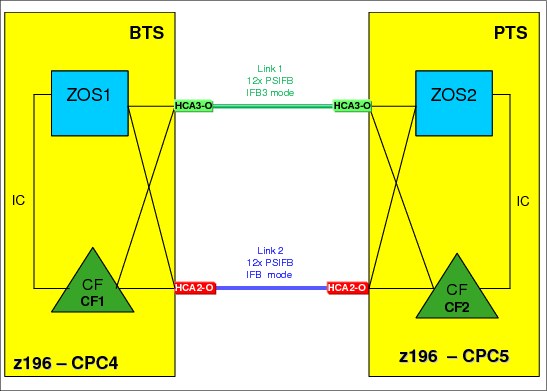
Figure 4-18 Scenario 5: Middle step
10. Middle step.
Now one link is running in IFB mode and one link is running in IFB3 mode. You can measure the performance of the IFB3 mode link by configuring offline the CHPIDs associated with the other link. However, be aware that doing this will create a single point of failure, because all online CHPIDs will now be using only one coupling link. It is advisable to perform such testing outside the online window, and to bring all CHPIDs back online as soon as your testing is complete.
11. Assuming that the PSIFB link 1 is working properly and that the performance is acceptable, repeat steps 4 to 10 for link 2.
12. The final configuration, with both links now migrated to HCA3-O 12X fanouts and running in IFB3 mode, is shown in Figure 4-19.

Figure 4-19 Scenario 5: Final configuration
4.8 Concurrent switch between IFB modes
This scenario describes the switch between the IFB modes.
In the case where a dynamic I/O configuration change results in an IFB protocol mode change on an HCA3-O port, the physical port will automatically perform reinitialize as soon as the change is activated. This will result in all defined CHPIDs on this port being toggled offline together and then online again. As a result, all connectivity to the Coupling Facility (or multiple Coupling Facilities, if multiple sysplexes are sharing the link) and STP through this port will be lost for a short period of time.
This means that you must ensure that all your CFs are connected through at least two physical links, and that any change you make is not going to affect more than one port.
This section describes a way to perform the switch in either direction concurrently to your sysplex operation. If you follow these steps carefully, you are able to switch between the two modes concurrently to your sysplex operations even though the mode switch is disruptive to each link by itself.
This scenario assumes that there are already two z196 CPCs at Driver 93 or later and that both CPCs have already HCA3-O 12X fanouts installed. Each CPC contains one z/OS LPAR and one CF LPAR. There are two 12x PSIFB links in place between the two CPCs, and each link has four CHPIDs defined. Because all the requirements for the use of IFB3 mode are being met, both links are utilizing the IFB3 mode at this time.
Figure 4-20 Switching between IFB modes - starting configuration
Concurrent switch from IFB3 to IFB mode
1. Starting point.
Our current configuration is shown in Figure 4-20.
2. Update HCD to add a fifth CHPID to one of the two links.
|
Note: This example is based on adding a fifth CHPID to one of the two 12x PSIFB links, because the mode switch will occur when we go above four defined CHPIDs. However, the behavior is the same for any number of CHPIDs above four.
|
3. Identify which CHPIDs will be impacted by the change.
It is vital to understand which CHPIDs will be affected when the port reinitializes itself, for a number of reasons:
– If you know the CHPIDs, you are able to determine which sysplexes will be affected.
– Knowing which CHPIDs will go offline allows you to check each sysplex to ensure that every CF is also connected by CHPIDs that will not go offline when the port reinitializes.
Use your configuration map, and the SEs of the affected CPCs, to identify the CHPIDs that will be affected by the change. For information about how to identify the CHPIDs that are assigned to a given port, refer to 7.4.2, “Determining the CHPIDs that are associated with an AID/port” on page 214.
4. Verify that all PSIFB CHPIDs are online.
Use the following z/OS commands in every z/OS system in every sysplex that will be affected by the change to determine which CHPIDs are online to each CF:
D CF,CFNM=CF1
D CF,CFNM=CF2
Check that there are online CHPIDs that are not associated with the port that is going to be affected by the change.
5. Perform the dynamic IODF activation on CPC4.
The new IODF for CPC4 is dynamically activated to add the fifth CHPID to PSIFB link 2. Figure 4-21 on page 115 shows the configuration after the dynamic activation.
When the IODF is activated, IXL158I messages might be generated, informing you that the CHPIDs associated with the port have gone offline, followed a few seconds later by more IXL158I messages, indicating that the CHPIDs are now online again.
|
Note: At this step, all defined CHPIDs to PSIFB link 2 are toggled offline and online by the CPC to reinitialize the PSIFB link in IFB mode. Depending on the utilization of your CF links, you might (or might not) see corresponding z/OS messages. But regardless of whether you get the corresponding z/OS messages, the PSIFB link is l reinitialized.
Also note that the ports at both ends of the link will reinitialize at this time. This is important because it means that the link will not go down a second time when the changed IODF on the other CPC is activated.
|

Figure 4-21 Configuration after CPC4 has five CHPIDs defined to PSIFB link 2
6. Dynamic IOCDS activation on CPC5.
The new IOCDS for CPC5 is dynamically activated to add the fifth CHPID to the PSIFB link 2.
|
Note: At this point, the PSIFB link is not reinitialized and all CHPIDs keep their connectivity.
|
7. Configure the fifth PSIFB CHPID online as required.
The new PSIFB CHPIDs (one at each end of the link) will now be configured online to the CF or z/OS LPARs that will be using them.
8. Verify that the all PSIFB CHPIDs are online.
Check the status of all coupling CHPIDs between the two CPCs to ensure that they have the expected status by using the following z/OS commands:
D CF,CFNM=CF1
D CF,CFNM=CF2
Remember to check both the logical and physical status of each CHPID, and also the state of the CHPIDs that are used by the CFs to communicate with each other.
You can check that all five CHPIDs which are defined for link 2 are now running in IFB mode through the “Analyze Channel Information” panel on the Service Element. Refer to “Analyze Channel Information option” on page 226 for more information. The configuration at this point is shown in Figure 4-22.

Figure 4-22 Configuration after both CPCs have five CHPIDs defined to PSIFB link 2
|
Attention: Make sure that you never make a change that alters the IFB mode of all links at the same time. Activating an IODF containing such a change can result in a loss of all coupling connectivity between the two CPCs.
|
Concurrent switch from IFB to IFB3 mode
1. Starting point.
The current configuration is shown in Figure 4-23 on page 117. The plan is to reduce the number of CHPIDs on link 2 to four to benefit from the better performance that is available in IFB3 mode.

Figure 4-23 Configuration where both CPCs have five CHPIDs defined to PSIFB link 2
2. Update HCD to remove the fifth CHPID from both ends of link 2.
3. Identify the CHPIDs that will be impacted by the change.
Remember, when the IFB mode of the port is changed, all CHPIDs using that port will temporarily go offline. This, it is not only the CHPID that is being removed that you need to consider.
Use your configuration map and the SEs of the affected CPCs to verify the CHPIDs that will be affected by the change. For information about how to identify the CHPIDs that are assigned to a given port, see 7.4.2, “Determining the CHPIDs that are associated with an AID/port” on page 214.
4. Verify that all PSIFB CHPIDs are online.
Use following z/OS commands in every z/OS system in every sysplex that will be affected by the change to determine which CHPIDs are online to each CF:
D CF,CFNM=CF1
D CF,CFNM=CF2
Check that there are online CHPIDs that are not associated with the port that is going to be affected by the change.
5. Configure the fifth PSIFB CHPID on the z/OS LPARs offline.
The fifth PSIFB CHPID is configured offline on z/OS LPARs “ZOS1” on CPC4 and “ZOS2” on CPC5. This is done with the following z/OS command (where xx stands for the CHPID):
CF CHP(xx),ONLINE
|
Note: It is also possible to use the “Configure Channel Path On/Off” function on the HMC or SE to toggle the channel online.
|
Also, see Chapter 7, “Operations” on page 189 for more details.
6. Configure offline the CHPID that is being removed.
Configure the CHPID that is being removed (on both ends of the link) offline to any LPAR that is using it. Remember that the CHPIDs might be in use by both CF and z/OS LPARs. Use the SE to verify that CHPIDs are offline in all LPARs before proceeding. See Chapter 7, “Operations” on page 189 for more details.
7. Perform the dynamic IODF activation on CPC4.
The new IODF for CPC4 is dynamically activated to remove the fifth CHPID from PSIFB link 2. Figure 4-24 shows the configuration after the dynamic activation.
When the IODF is activated, IXL158I messages might be generated, informing you that the CHPIDs associated with the port have gone offline, followed a few seconds later by more IXL158I messages, indicating that the CHPIDs are now online again.
|
Note: At this step, all CHPIDs defined on PSIFB link 2 are toggled offline and online by the CPC to reinitialize the PSIFB link. However, the mode is not switched because the port at the other end of the link still has five CHPIDs defined.
Depending on the utilization of your CF links, you might (or might not) see corresponding z/OS messages. However, even if you do not see any IXL158I messages, the PSIFB link is reinitialized.
|

Figure 4-24 Configuration after CPC4 has only four CHPIDs defined to PSIFB link 2
8. Perform the dynamic IODF activation on CPC5.
The updated IODF is activated on CPC5 to remove the fifth CHPID from PSIFB link 2.
|
Note: At this point, all CHPIDs defined on PSIFB link 2 are again toggled offline and online by the CPC to reinitialize the PSIFB link in IFB3 mode. Once again, you might (or might not) see corresponding z/OS messages.
|
9. Verify that the all PSIFB CHPIDs are online.
Check that all CHPIDs have the expected status. Use the following z/OS commands to make sure that all CHPIDs, including those between the CFs, are online:
D CF,CFNM=CF1
D CF,CFNM=CF2
To verify that the links are now operating in IFB3 mode, use the “Analyze Channel Information” panel on the Service Element. See “Analyze Channel Information option” on page 226 for more information.

Figure 4-25 Configuration after both CPCs have four CHPIDs defined to PSIFB link 2
10. The final configuration is shown in Figure 4-25.
1 The PTS should always be the last CPC to be shut down, and the first CPC to be restarted, so ensure that the CPC that is not being upgraded is the one that is the PTS. Therefore, prior to making any other STP-related changes, make the CPC that is not being upgraded the PTS if that is not already the case; in this example, that is the z10 EC. If you need to make changes to the STP configuration to achieve this, work those changes into the process described here.
2 Enabling this option causes the CTN’s timing and configuration settings to be saved so that they will not need to be re-entered after a loss of power or a planned POR of the servers.
3 If a CPC is activated with an IOCDS that was not previously used, all CHPIDs will be brought online as part of the activation, regardless of the status of the CHPIDs before the CPC was powered down.
4 The PTS should always be the last CPC to be shut down, and the first CPC to be restarted, so ensure that the CPC that is not being upgraded is the one that is the PTS. Therefore, prior to making any other STP-related changes, make the CPC that is not being upgraded the PTS if that is not already the case. In this example, that is the z10 EC. If you need to make changes to the STP configuration to achieve this, work those changes into the process described here.
5 Enabling this option causes the CTN’s timing and configuration settings to be saved so that they will not need to be re-entered after a loss of power or a planned POR of the servers.
..................Content has been hidden....................
You can't read the all page of ebook, please click here login for view all page.