

Preinstallation planning
In this chapter, we provide information to assist you with planning for the installation of InfiniBand coupling links on IBM zEC12, zBC12, zEnterprise 196, zEnterprise 114, and System z10 CPCs.
3.1 Planning considerations
To ensure that your migration to InfiniBand coupling links takes place as transparently as possible, having a well-researched and documented implementation plan is critical. To assist you in creating your plan, we discuss the following topics in this chapter:
•Planning the topology of the CPC types you will connect using PSIFB coupling links
There are differences in the implementation of PSIFB on z196, z114, z10, and z9.
•Planning for the hardware and software prerequisites
In addition to the minimum hardware and software levels that are necessary to install and define the PSIFB coupling links, there are restrictions on the type of CPCs that can coexist in a Parallel Sysplex.
•Considerations for Server Time Protocol
In addition to its use to connect z/OS and CF LPARs, InfiniBand also provides connectivity for the members of a Coordinated Timing Network.
•Planning for connectivity in a sysplex that spans multiple data centers
InfiniBand provides potential performance and cost-saving advantages over ISC3 links for connecting a sysplex that spans many kilometers.
•Planning for future growth with minimal disruption
Because stand-alone CFs do not have the ability to do a dynamic reconfiguration, adding coupling links normally requires a POR of the CF CPC. However, changes introduced in z/OS 1.13, together with advance planning, provide the ability to add coupling link capacity without requiring an outage of the affected CF LPAR.
•Determining how many physical coupling links and logical CHPIDs you require
The number of coupling links you require reflects your connectivity requirements (how many CPCs must be connected to each other and how many sysplexes span those CPCs), availability requirements (making sure that there are no single points of failure), and capacity and performance requirements.
•Preparing the information that you need to define your configuration to hardware configuration definition (HCD)
This involves planning your adapter IDs (AIDs) for the PSIFB coupling links and the channel path identifiers (CHPIDs) that will be assigned to them. The InfiniBand host channel adapters (HCAs) are represented by an identifier called an AID, and multiple CHPIDs can be defined to the ports associated with the AID.
•Planning your cabling requirements
PSIFB coupling links might require new types of cable and connectors, depending on the type of links that are being used prior to the InfiniBand links.
3.2 CPC topology
PSIFB links are available on IBM zEC12, zBC12, z196, z114, z10, and z9 CPCs. They support the use of coupling and timing-only links between these CPCs.
The full list of supported link types for these CPCs is contained in Table 3-1 on page 41.
3.2.1 Coexistence
You must consider the requirements for CPC coexistence when implementing PSIFB coupling links. The z196 and z114 CPCs can only coexist in a Parallel Sysplex or a Coordinate Timing Network (CTN) with z10 (EC or BC) and z9 (EC or BC) CPCs. You must remove any earlier CPCs (such as z990, z890, z900, and z800) from the Parallel Sysplex or CTN or replace them with a supported CPC before you can add a z196 or z114 to the sysplex. This statement applies regardless of the type of coupling link that is being used.
Figure 3-1 illustrates the supported coexistence environments and the types of supported coupling links for z196, z10, and z9 CPCs. For detailed hardware prerequisites, see 3.3.1, “Hardware prerequisites” on page 42.
|
Note: z9 CPCs cannot be coupled to other z9 CPCs using PSIFB links.
|

Figure 3-1 Coupling link configuration options and supported coexistence for zEnterprise 196/114
Figure 3-2 shows the supported coexistence environments and the types of supported coupling links for zEC12, zBC12, z196, z114, and z10 CPCs. Remember that a Parallel Sysplex or a CTN can only contain three consecutive generations of System z servers, so the guidelines that are related to upgrading or removing older CPCs that apply to z196 and z114 also apply to zEC12 and zBC12.

Figure 3-2 Coupling link configuration options and supported coexistence for zEC12 and zBC12
Also, remember that z196 and later do not support IBM Sysplex Timer connection, so you must have commenced your migration to STP mode prior to installing your first z196 or later CPC, and must plan on completing the migration before removing the last pre-z196 CPC.
Also, z196 and later CPCs do not support ICB4 links. If your current coupling infrastructure uses ICB4 links, you must migrate to InfiniBand before installing your first z196 or later CPC if you want to connect that CPC to the other CPCs in your configuration.
3.2.2 Supported coupling link types
|
Statement Of Direction: The zEnterprise 196 and zEnterprise 114 will be the last generation of System z CPCs to support ordering of ISC3 links. However, it will be possible to carry forward ISC3 links on an upgrade from earlier CPC generations.
zEC12 and zBC12 also support carry forward of ISC3 links on an upgrade. However, this is the last generation of System z CPC that will support this capability.
|
IBM z196 and later CPCs support up to 128 CF link CHPIDs. Table 3-1 on page 41 summarizes the maximum number of physical coupling links that are supported for each CPC type.
Table 3-1 Maximum number of coupling links supported
|
Link type
|
Maximum supported links1
|
|||||||
|
zEC12
|
zBC12
|
z1962
|
z114
|
z10 EC3
|
z10 BC
|
z9 EC
|
z9 BC
|
|
|
IC
|
32
|
32
|
32
|
32
|
32
|
32
|
32
|
32
|
|
ISC3
|
484
|
32
|
48
|
48
|
48
|
48
|
48
|
48
|
|
ICB4
|
n/a
|
n/a
|
n/a
|
n/a
|
16
|
12
|
16
|
16
|
|
ICB3
|
n/a
|
n/a
|
n/a
|
n/a
|
n/a
|
n/a
|
16
|
16
|
|
HCA1-O (12X IFB)5
|
n/a
|
n/a
|
n/a
|
n/a
|
n/a
|
n/a
|
16
|
12
|
|
HCA2-O LR (1X IFB)6
|
32
|
12
|
327
|
128
|
329
|
12
|
n/a
|
n/a
|
|
HCA2-O (12X IFB)
|
32
|
16
|
32g
|
16h
|
32i
|
12
|
n/a
|
n/a
|
|
HCA3-O LR (1X IFB)10
|
64
|
32
|
4811
|
3212
|
n/a
|
n/a
|
n/a
|
n/a
|
|
HCA3-O (12X IFB & 12X IFB3)j
|
32
|
16
|
32k
|
16l
|
n/a
|
n/a
|
n/a
|
n/a
|
|
Max External Links13
|
104
|
72
|
10414
|
72n
|
6415
|
64
|
64
|
64
|
|
Max Coupling CHPIDs16
|
128
|
128
|
128
|
128
|
64
|
64
|
64
|
64
|
1 Maximum number of coupling links combined (ICB, PSIFB, ISC3, and IC) for all System z10 and z9 CPCs is 64. The limit for zEnterprise CPCs has been increased to 128.
2 Maximum of 56 PSIFB links on z196.
3 Maximum of 32 PSIFB links and ICB4 links on z10 EC. ICB4 links are not supported on model E64.
4 zEC12 only supports ISC3, HCA2-O, and HCA2-LR adapters when carried forward as part of an upgrade.
5 HCA1-O is only available on System z9 (withdrawn from marketing in June 2010).
6 HCA2-O LR adapters are still available for z10, however they have been withdrawn from marketing for z196 and z114. On z196 and z114, HCA3-O LR functionally replaces HCA2-O LR.
7 A maximum of 16 HCA2-O LR and HCA2-O coupling links are supported on the z196 model M15.
8 A maximum of 8 HCA2-O LR and HCA2-O coupling links are supported on the z114 model M05.
9 A maximum of 16 HCA2-O LR and HCA2-O coupling links are supported on the z10 model E12.
10 HCA3-O and HCA3-O LR are only available on z196 and z114.
11 A maximum of 32 HCA3-O LR and 16 HCA3-O coupling links are supported on the z196 model M15.
12 A maximum of 16 HCA3-O LR and 8 HCA3-O coupling links are supported on the z114 model M05.
13 Maximum external links is the maximum total number of physical link ports (does not include IC).
14 The number of maximum external links is dependent on the number of HCA fanout slots available. The maximum of 104 external links (72 for z114) can only be achieved with a combination of ISC3, HCA3-O LR, and HCA3-O links.
15 Maximum number of external links for all z10 and z9 CPCs is 64.
16 Maximum coupling CHPIDs defined in IOCDS include IC and multiple CHPIDs defined on PSIFB links.
|
Important: Be aware of the following points:
For z196 and zEC12, the maximum number of external links and the maximum number of CHPIDs that can be defined are 104 and 128, respectively.
For z114 and zBC12, the maximum number of external links and the maximum number of CHPIDs that can be defined are 72 and 128, respectively.
For z10 and z9, the maximum number of coupling links and the maximum number of CHPIDs that can be defined are both 64.
The use of internal coupling (IC) links and assigning multiple CHPIDs to a PSIFB link can cause the CHPID limit to be reached before the maximum number of physical links.
|
Supported CHPID types for PSIFB links
All PSIFB coupling link CHPIDs are defined to HCD as type CIB. They conform to the general rules for Coupling Facility peer channels (TYPE=CFP, TYPE=CBP, TYPE=ICP, or TYPE=CIB).
You can configure a CFP, CBP, ICP, or CIB CHPID as:
•A dedicated CHPID to a single LPAR.
•A dedicated reconfigurable CHPID that can be configured to only one CF LPAR at a time, but that can be dynamically moved to another CF LPAR in the same CSS.
•A shared CHPID that can be concurrently used by LPARs in the same CSS to which it is configured.
•A spanned CHPID that can be concurrently used by LPARs in more than one CSS.
For further details, see 6.4.1, “Input/output configuration program support for PSIFB links” on page 161.
3.3 Hardware and software prerequisites
In this section, we discuss the hardware and software prerequisites for implementing PSIFB links on the z9 and later CPCs.
3.3.1 Hardware prerequisites
The implementation of PSIFB coupling links requires a zEnterprise, z10, or z9 CPC. The base prerequisites for PSIFB are satisfied by the base zEnterprise or z10 models at general availability. The recommended microcode levels are highlighted as part of the order process.
When installing an MES, the required microcode levels are documented in the MES installation instructions. When installing a new machine with HCA adapters installed, there is a minimum code requirement documented in the appropriate Solution Assurance Product Review (SAPR) guide that is available to your IBM representative.
Additional hardware system area (HSA) is required to support the HCA1-O fanout on a z9 CPC. For z9, a power-on reset (POR) is required when the first PSIFB feature is installed; however, this is not necessary on later CPCs.
See 2.2, “InfiniBand fanouts” on page 19 for a detailed description of the InfiniBand fanouts that are offered on zEnterprise and System z CPCs.
Bring your CPCs to at least the Driver and bundle levels shown in Table 3-2 prior to moving to InfiniBand. CPCs older than z9 are not supported in the same Parallel Sysplex or CTN as z196 or z114. CPCs older than z10 are not supported in the same Parallel Sysplex or CTN as zEC12 or zBC12.
Table 3-2 Recommended minimum hardware service levels
|
CPC
|
Recommended Driver
|
Recommended minimum bundle level
|
|
z9
|
67L
|
63
|
|
z10
|
79
|
511
|
|
z196 GA12
|
86
|
38
|
|
z196 GA2 and z114
|
93
|
133
|
|
zEC12 GA1
|
12
|
38
|
|
zEC12 GA2, zBC12
|
15
|
6B
|
1 Minimum level required to couple z10 HCA2 adapters to HCA3 adapters is Bundle 46.
2 Minimum required to couple HCA2 adapters to HCA3 adapters.
3 If the CPC will have both HCA2 12X and HCA3 12X links to the same CF, install Bundle 18 or later.
3.3.2 Software prerequisites
PSIFB links are supported by z/OS 1.7 and later releases. Several releases might require additional program temporary fixes (PTFs) in support of PSIFB.
The information necessary to identify the required service is available in the following Preventive Service Planning (PSP) buckets:
•2097DEVICE for z10 EC
•2098DEVICE for z10 BC
•2817DEVICE for z196
•2818DEVICE for z114
•2827DEVICE for zEC12
•2828DEVICE for zBC12
Rather than using the PSP buckets, however, we suggest using the SMP/E REPORT MISSINGFIX command in conjunction with the FIXCAT type of HOLDDATA. The PSP upgrades and the corresponding FIXCAT names are shown in Table 3-3. Because of the relationship between STP and InfiniBand, we have included the STP FIXCATs in the table1.
Table 3-3 PSP bucket upgrades and FIXCAT values for z/OS CPCs
|
CPC
|
Upgrade
|
FIXCAT value
|
|
zEC12
|
2827DEVICE
|
IBM.Device.Server.zEC12-2827
IBM.Device.Server.zEC12-2827.ParallelSysplexInfiniBandCoupling
IBM.Device.Server.zEC12-2827.ServerTimeProtocol
|
|
zBC12
|
2828DEVICE
|
IBM.Device.Server.zBC12-2828
IBM.Device.Server.zBC12-2828.ParallelSysplexInfiniBandCoupling
IBM.Device.Server.zBC12-2828.ServerTimeProtocol
|
|
z196
|
2817DEVICE
|
IBM.Device.Server.z196-2817
IBM.Device.Server.z196-2817.ParallelSysplexInfiniBandCoupling
IBM.Device.Server.z196-2817.ServerTimeProtocol
|
|
z114
|
2818DEVICE
|
IBM.Device.Server.z114-2818
IBM.Device.Server.z114-2818.ParallelSysplexInfiniBandCoupling
IBM.Device.Server.z114-2818.ServerTimeProtocol
|
|
z10 EC
|
2097DEVICE
|
IBM.Device.Server.z10-EC-2097
IBM.Device.Server.z10-EC-2097.ParallelSysplexInfiniBandCoupling
IBM.Device.Server.z10-EC-2097.ServerTimeProtocol
|
|
z10 BC
|
2098DEVICE
|
IBM.Device.Server.z10-BC-2098
IBM.Device.Server.z10-BC-2098.ParallelSysplexInfiniBandCoupling
IBM.Device.Server.z10-BC-2098.ServerTimeProtocol
|
You must review the PSP information or REPORT MISSINGFIX output from SMP/E early in the planning process to allow time for ordering any necessary software maintenance and then rolling it out to all the members of all your sysplexes. Example 3-1 shows a sample REPORT MISSINGFIX output for z196.
Example 3-1 Sample REPORT MISSINGFIX output for InfiniBand
MISSING FIXCAT SYSMOD REPORT FOR ZONE ZOSTZON
HOLD MISSING HELD _____RESOLVING SYSMOD____
FIX CATEGORY FMID CLASS APAR SYSMOD NAME STATUS RECEIVED
_______________ _______ _______ _______ _______ _______ ______ _______
IBM.Device.server.z196-2817.ParallelSysplexInfiniBandCoupling
HBB7750 AA25400 HBB7750 UA43825 GOOD YES
Additionally, we recommend that all System z clients subscribe to the IBM System z Red Alert service. For more information, see the following subscription site:
If you want to exploit the 32 subchannels per CHPID functionality, ensure that both your hardware and HCD support levels are correct. Figure 3-3 shows the CPC options that are presented after the HCD PTF to support 32 subchannels per coupling CHPID has been installed. See Chapter 6, “Configuration management” on page 155 for more information.
|
Command ===> ___________________________________________ Scroll ===> PAGE
Select one to view more details.
Processor
Type-Model Support Level
# 2817-M32
2817-M49 XMP, 2817 support, SS 2, 32 CIB CF LINKS
# 2817-M49
2817-M66 XMP, 2817 support, SS 2, 32 CIB CF LINKS
# 2817-M66
2817-M80 XMP, 2817 support, SS 2, 32 CIB CF LINKS
# 2817-M80
|
Figure 3-3 HCD processor type support levels for zEnterprise CPCs
|
Note: The ability to define 32 subchannels for PSIFB links in HCD and input/output configuration program (IOCP) is provided by APARs OA32576 and OA35579. Those APARs changed the default number of subchannels for all CF link CHPIDs to 32. APAR OA36617 subsequently changed the default back to seven. You should only specify 32 subchannels if the link will span two sites.
Review REPORT MISSINGFIX output and PSP information to ensure that you have the latest required service.
|
3.4 Considerations for Server Time Protocol
Server Time Protocol (STP) provides a coordinated time source for systems connected through coupling links. It replaces the Sysplex Timer (9037) as the time source for interconnected systems.
STP uses coupling links to transmit time signals between interconnected systems. All types of PSIFB coupling links (on supported CPCs) can be used to transmit STP timing signals in a Coordinated Timing Network. STP interconnectivity using other types of coupling links (ISC3, ICB4) are also possible on CPCs that support them.
|
Note: Connection to Sysplex Timer (ETR) is not supported on z196 and later.
The use of STP is required for time synchronization in a Coordinated Timing Network containing these CPCs.
|
3.4.1 Considerations for STP with PSIFB coupling links
STP communication is at the CPC level, not the LPAR level. This means that STP communication is not dependent on any particular LPAR being available or even activated. Also, the speed of STP links (ISC3, ICB4, or PSIFB) has no impact on STP performance or timing accuracy. However, you need to carefully consider the STP CPC roles and coupling link connectivity when planning the links for your Coordinated Timing Network (CTN).
Server roles and connectivity
There are several server roles within an STP-only CTN. These are defined using the “System (Sysplex) Time” icon on the HMC:
•Current Time Server (CTS)
The Current Time Server is the active stratum 1 server and provides the time source in an STP-only CTN. Only the Preferred Time Server or Backup Time Server can operate as the CTS.
•Preferred Time Server (PTS)
This refers to the server that has preference to operate as the CTS and Stratum 1 server of the STP-only CTN is assigned the role of Preferred Time Server. This server requires connectivity to the Backup Time Server and the Arbiter (if present).
•Backup Time Server (BTS)
Although this is an optional role, it is strongly recommended. This server will take over as the CTS and Stratum 1 server in recovery conditions or as part of a planned maintenance operation to the PTS. The BTS requires connectivity to the PTS and Arbiter (if present).
•Arbiter
This is an optional role, although it is strongly recommended when three or more servers participate in the CTN. The Arbiter provides additional validation of role changes for planned or unplanned events that affect the CTN. The Arbiter is a stratum 2 server that should have connectivity to both the PTS and the BTS.
•Alternate servers
Any time a PTS, BTS, or Arbiter is going to be removed from service, move that role to another member of the CTN. Make sure that alternate server has the same connectivity as the server that it is replacing.
For more information, refer to Important Considerations for STP server role assignments, available on the web at the following site:
•All other servers
The remaining servers in the CTN should have two failure-isolated links to the PTS and the BTS, and also to the alternate locations for those roles.

Figure 3-4 Sample STP server roles and connectivity with coupling links
Figure 3-4 shows a CTN with the following elements:
•There are two stand-alone CFs:
– C1 is the PTS and CTS.
– C2 is the BTS
•P1, P2, P3, and P4 all contain z/OS systems participating in the Parallel Sysplex.
•P1 is the Arbiter.
•The PTS, BTS, and Arbiter must be connected to each other.
•Additional coupling links have been defined between the PTS and BTS for STP purposes only.
There might be a requirement to configure links between two servers in the CTN that have only z/OS LPARs defined. With no Coupling Facility LPARs at either end of the link, the links must be defined as timing-only links. A timing-only link is shown in Figure 3-5 between P3 and P4.

Figure 3-5 Sample STP server roles and connectivity with coupling and timing-only links
|
Note: Be aware of the following points:
•A timing-only link can only be defined when the CPCs at either end of the link contains no CF LPARs.
•A mixture of Timing-only and coupling links is not allowed between the same pair of servers. HCD will not allow this definition.
•The PTS, BTS and Arbiter must be connected to each other.
•Define at least two failure-isolated coupling links or timing-only links between each pair of servers for redundancy.
|
To ensure the highest levels of availability, it is vital that all servers in the CTN are able to receive timing signals from the CTS or a stratum 2 server at all times. The best way to avoid connectivity failures that impact STP is to ensure that every server is connected to the PTS and the BTS (and their backups) by two failure-isolated coupling links. STP is designed to issue a warning message if it detects that it only has one path to the CTS. However, STP is not aware of the underlying InfiniBand infrastructure; it only sees CHPIDs. So, if there are two online CHPIDs to the CTS, but both of those CHPIDs are using the same InfiniBand link, STP will not be aware of that and therefore not issue a warning message.
Also note that STP’s ability to use a coupling link for timing signals is independent of any LPARs. So, for example, following the successful completion of a power-on reset, all coupling CHPIDs should be available for STP use, regardless of whether any LPARs are activated or not. Similarly, if the LPAR that owns a coupling link that is currently being used by STP is deactivated, that does not stop STP from using that link. For additional information about STP, see Server Time Protocol Planning Guide, SG24-7280.
3.5 Multisite sysplex considerations
Extended distance sysplex connectivity is provided by ISC3 and PSIFB 1X links. The maximum unrepeated distance of both these link types is 10 km (20 km with RPQ2). Distances greater than this require a Dense Wave Division Multiplexer (DWDM).
Careful planning is needed to ensure there are redundant and diverse fiber routes between sites to avoid single points of failure on a fibre trunk.
IBM supports only those DWDM products qualified by IBM for use in high availability, multi-site sysplex solutions, such as GDPS. The latest list of qualified DWDM vendor products can be found on the IBM Resource Link® website at the following link:
|
Important: Check the qualification letters in detail to determine your precise requirements and how best to address those requirements:
•Selecting a qualified WDM vendor does not necessarily mean that the selected WDM model is qualified.
•Selecting a qualified WDM model does not mean that a specific release level is qualified.
•A vendor’s WDM model might be qualified for ISC3 or PSIFB 1X links for transfer of CF requests but not qualified for ISC3 or PSIFB 1X IFB links when also exchanging STP messages.
•Ensure that the vendor qualification letter is inspected carefully by a DWDM technical expert. The letter specifies model number, release level, interface modules qualified, protocols, application limitations and so on.
•The maximum supported distance is not the same for all vendors, and changes over time as new devices, features, and capabilities are introduced and qualified.
For more information about qualified WDMs, search on the keywords “qualified WDM” on the Redbooks website at the following link:
|
To transmit timing information, STP can choose any defined coupling link or timing-only link that is online between two IBM zEnterprise or System z CPCs; you cannot limit STP to only certain CHPIDs. This means that you must not configure the links over a mixture of qualified and unqualified equipment. Doing so might result in timing problems where CPCs might become unsynchronized without your knowledge. When coupling links or timing-only links are configured over DWDM equipment, all links must use specific DWDM hardware (optical modules, transponders, TDM modules) with interface cards qualified by IBM for the STP protocol.
Coupling Facility response times at extended distances
Coupling Facility (CF) performance needs especially careful consideration when the CF is located at a significant distance away from the connected z/OS or CF CPC.
As the distance between the z/OS and CF CPCs increases, the speed of light becomes the dominant factor in the response time, adding around 10 microseconds per km for the round trip to the CF. This results in a direct impact to the service time, and most synchronous requests being converted to asynchronous.
Because the subchannel and link buffer that are used for the CF request are allocated for the entire duration of the service time, the increased service times caused by the distance result in high subchannel and link buffer usage and potentially more subchannel delay and Path Busy events. There are two attributes of InfiniBand links that can be particularly beneficial to long-distance sysplexes:
•On zEnterprise CPCs using Driver 93 and later, 1X InfiniBand links support either 7 or 32 subchannels per CHPID, compared to the 7 subchannels per CHPID that were supported previously.
This means that more CF requests can be active concurrently on each CHPID, reducing instances of requests being delayed because all subchannels or link buffers are busy.
•The ability to define multiple CHPIDs to a single PSIFB link can help because additional CHPIDs (which provide more subchannels) can be added without having to add more physical links.
With ISC links, you were limited to seven subchannels per link, and a maximum of eight links between a z/OS and a CF, giving a maximum of 56 subchannels. With PSIFB 1X links prior to Driver 93, you were still able to have only seven subchannels per CHPID. However, you were able to have your eight CHPIDs to the CF spread over just two physical links, which is a significant decrease in the number of required adapters and DWDM ports. With PSIFB 1X links and Driver 93, the same eight CHPIDs support 256 subchannels.
For more information about the relationships between subchannels and link buffers and how they are used, see Appendix C, “Link buffers and subchannels” on page 247.
Find additional reference information in the following documents:
•Considerations for Multisite Sysplex Data Sharing, SG24-7263
•IBM System z Connectivity Handbook, SG24-5444
•Server Time Protocol Planning Guide, SG24-7280
3.6 Planning for future nondisruptive growth
If your CF LPARs reside in the same CPC as z/OS or IBM z/VM, it is possible to add links to the CF dynamically by using the dynamic reconfiguration support provided by these operating systems. This means that as your configuration and capacity requirements increase in the future, you can add more physical links and more CHPIDs dynamically. But if your CF LPARs reside in a CPC with no operating system (no z/OS or z/VM LPARs), there is currently no way to add links or CHPIDs to that CPC without a POR.
For coupling links prior to InfiniBand, you were able to define and install a link in the CF CPC at one time, and then add a corresponding link in the z/OS CPC later. A POR was required to add the link to the CF CPC. But when the link is later added to the z/OS CPC, a dynamic reconfiguration can be used to make the link available to LPARs on the z/OS CPC, and no POR is required on the CF CPC. This means that when the link is installed in the z/OS CPC, you are immediately able to use it without interrupting CF operations.
However, prior to z/OS 1.13, when you define an InfiniBand CHPID, both the CF and the z/OS CHPIDs must be defined and must be connected to each other3. And because you must specify the AID when you define the InfiniBand CHPID, you cannot define the CHPID unless the link was already installed or an order had been placed and the eConfig report providing the AID is available. This effectively meant that you had to install the InfiniBand adapter in the CF and z/OS CPCs at the same time.
This restriction is alleviated starting with z/OS 1.13 (and rolled back to z/OS 1.10 with APAR OA29367). HCD will now accept an AID of an asterisk (*), meaning that you can install the adapter in the CF CPC now and assign the real AID, but for the z/OS end you use a placeholder AID of *. Then, when the adapter is subsequently installed in the z/OS CPC, you replace * with the real AID and perform a dynamic reconfiguration. When the reconfiguration completes, the new coupling link can be used without having to perform another POR on the CF CPC.
This support and its use is discussed in more detail in “Overdefining CIB links” on page 160.
3.7 Physical and logical coupling link capacity planning
All sysplex clients will have to migrate to InfiniBand over the next few years as they move to newer CPC generations. An InfiniBand infrastructure is significantly different from a pre-InfiniBand infrastructure and will involve replacing all your previous coupling infrastructure with InfiniBand links.
Therefore, the migration presents an ideal opportunity to ensure that the infrastructure that you configure will deliver the best possible availability, performance, and flexibility, in the most cost-effective manner.
To obtain the optimum benefit from this opportunity, rather than simply replacing your existing configuration with an equivalent number of PSIFB links, you can go through an exercise to determine the most appropriate configuration for your environment.
In this section we discuss the various aspects of your coupling infrastructure, and help you identify the number of physical InfiniBand links and the connectivity that you need. We then discuss the best way to configure that hardware for optimum performance.
3.7.1 Availability
Because the Coupling Facility is the heart of your Parallel Sysplex, it is vital that all systems in the sysplex have access to it at all times. If one member of the sysplex loses all access to a Coupling Facility, it is likely that all the contents of the CF will be moved to another CF, meaning that the capacity of that CF will be lost to the sysplex until connectivity can be restored. This also potentially creates a single point of failure if all structures now reside in the same CF.
To avoid this situation, there are guidelines to follow when planning the availability aspects of your PSIFB infrastructure:
•Always configure at least two physical links between each pair of connected CPCs.
It is important to have no single points of failure in the connection between z/OS and the CFs. This means using more than one physical link, and distributing those links over multiple HCAs.
Additionally, if the CPC contains more than one book, distribute the links to each connected CPC over multiple books (both in the z/OS CPC and in the CPC containing the CF). Plan availability by BOOK/HCA/PORT.
For example, if you decide to have two CF link CHPIDs and two PSIFB links, and multiple books are available in your CPC, your two CHPIDs can be mapped as follows:
– CHPID 00 - BOOK 0, HCA1, PORT 1
– CHPID 01 - BOOK 1, HCA2, PORT 1
In a single book system this is not possible, so spread your links across multiple HCAs.
|
Note: At the time of writing, the various functions in z/OS that check for single points of failure are unaware of the relationship between CHPIDs and the underlying InfiniBand infrastructure.
If two CHPIDs are online to the CF, those functions will assume that those CHPIDs do not represent a single point of failure.
This places extra responsibility on you to ensure that you design a robust configuration and to ensure on an ongoing basis that no real single points of failure exist.
|
•When planning your physical configuration, be aware that different CPC types support differing numbers of fanouts. For large configurations, it might be necessary to configure multiple books to provide the number of required fanouts. Refer to the footnotes in Table 3-1 on page 41 for more details.
Additionally, depending on your availability requirements, you might decide to add a second book for availability rather than purely for capacity reasons.
•The CHPID Mapping Tool (CMT) does not provide a CHPID availability mapping function for InfiniBand links. However, it will validate that your manual mapping does not contain any intersects. To understand the process better, refer to “CHPID Mapping Tool support” on page 183.
In addition to their use for providing connectivity between z/OS and CF LPARs, coupling links are also used to provide connectivity for STP signaling. For a CPC to be part of a multiCPC sysplex, it must be able to send and receive timing signals to and from other members of the timing network. When using STP, these signals are sent and received over coupling links, so configure each CPC so that it has two failure-isolated connections to the PTS, the BTS, and to any CPC that might take over those roles during an outage. For more information, see Redbooks Server Time Protocol Planning Guide, SG24-7280 and Server Time Protocol Recovery Guide, SG24-7380.
The number of physical links that you require between each pair of CPCs will reflect a balance of availability and performance. InfiniBand is a powerful and flexible interconnect architecture where only significantly high volume workloads are likely to require more than two physical links between connecting CPCs. However, for availability reasons, every pair of connected CPCs should have at least two failure-isolated physical links, regardless of the bandwidth requirements.
Figure 3-6 shows two configurations. The configuration on the left side has two CPCs, with one HCA fanout on each CPC. Although this provides connectivity and sufficient bandwidth, both links are connected to the same adapter, meaning that all communication between the two CPCs will be lost if that adapter were to fail. The preferred solution is to install two fanouts in each CPC and use one port in each adapter, as shown in the configuration on the right side.

Figure 3-6 Configuring for availability
|
Important: Configure a minimum of two physical InfiniBand links connected to different HCAs between every pair of connected CPCs.
Defining multiple CHPIDs on a single physical PSIFB coupling link does not satisfy the high availability recommendation. You must implement multiple physical links, on multiple HCAs, to avoid single points of failure.
|
3.7.2 Connectivity
When determining the number of PSIFB links you require on a CPC, one of the considerations is the number of other CPCs that it will need to connect to. Prior to InfiniBand links, the number of links was driven by the number of CPCs that needed to be interconnected (the physical configuration), the performance considerations, and the number of sysplexes (the logical configuration), because pre-InfiniBand coupling links cannot be shared between multiple sysplexes.
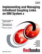
Prior to InfiniBand, each z/OS CPC required at least two links (for availability reasons) per sysplex for each connected CF. If you had two sysplexes, two z/OS CPCs, two CF CPCs, and are using System Managed Duplexing, you need at least ten links. This is shown in the configuration diagram in Figure 3-7.

Figure 3-7 Pre-InfiniBand configuration with two sysplexes
Additionally, if you want to provide STP connectivity between the two z/OS CPCs (which is highly recommended in a configuration like this), an additional two timing-only links are required between that pair of CPCs.
Also remember that if System Managed Duplexing is being exploited, you need a pair of links for each pair of CF LPARs4. So two sysplexes, with both sysplexes using System Managed Duplexing, require at least twenty links, as shown in Figure 3-8.
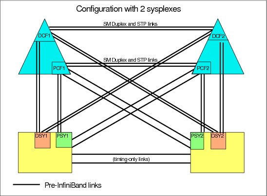
Figure 3-8 Pre-InfiniBand configuration with two sysplexes
And that is with just four CPCs, two sysplexes, and a minimum number of links between each z/OS and its CFs. Imagine a configuration with eight sysplexes (as some clients have). Or four or more coupling links from each z/OS CPC for each sysplex. As the number of CPCs, systems, coupling links, and CFs increases, the physical connectivity requirement increases dramatically.
Because InfiniBand supports the ability to share physical links across multiple sysplexes, the number of sysplexes is less likely to be a factor in the number of coupling links you require5.
Figure 3-9 shows how the use of InfiniBand simplifies the configuration by supporting multiple sysplexes over (in this case) just two InfiniBand links between each pair of CPCs. This example has twice as many sysplexes as the configuration shown in Figure 3-8 on page 54, and yet it only has half as many coupling links.
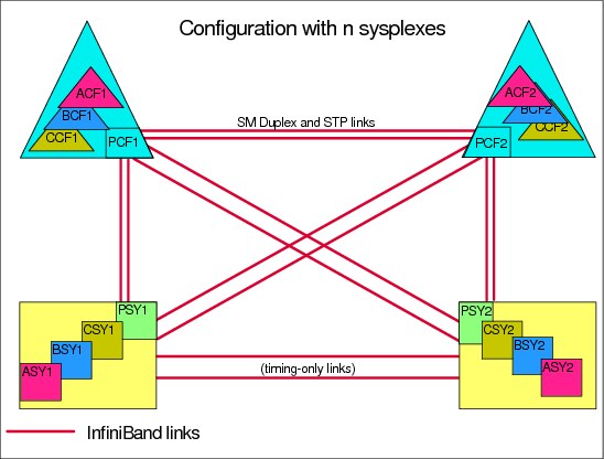
Figure 3-9 InfiniBand support for multiple sysplexes
At some point, the capacity or connectivity requirements of the sysplexes might drive a need for more links. However, in most cases, the required number of links reflects the number of CPCs to be connected and the required capacity, and not the number of sysplexes.
|
Summary: After you have mapped out the links you will need for availability and STP connectivity, verify that connectivity is sufficient to connect every z/OS LPAR to each CF in the same sysplex.
Providing timing-only links between the z/OS CPCs is highly recommended because it provides additional flexibility in the placement of the STP roles during outages.
|
3.7.3 Capacity and performance
The third aspect of planning your InfiniBand connectivity is to ensure that the number of links you plan will provide acceptable performance.
There are two aspects to how coupling links contribute to performance:
Capacity If you are trying to send 1 GB of data to a cache structure in the CF every second, your coupling link infrastructure must be capable of handling that volume of traffic. This is typically referred to as bandwidth: the larger the bandwidth, the more data can be moved in a given amount of time.
Response time The response time for a synchronous CF request consists of:
1) Potentially having to wait for an available link buffer or subchannel.
2) Latency within the hardware before the request is placed on the link.
3) The size of the request and the bandwidth of the link.
4) The distance between the z/OS LPAR and the CF LPAR.
5) The speed and utilization of the CF.
Items 2 and 3 in this list are directly impacted by the link technology.
Different coupling link types support different bandwidths. For example, 12X InfiniBand links have a larger bandwidth than 1X InfiniBand links. This means that a 12X link can process more requests per second than a 1X link (all other things being equal). The relationship between bandwidth and response time is discussed in 1.5.1, “Coupling link performance factors” on page 11.
IBM RMF does not provide any information about the bandwidth utilization of coupling CHPIDs. For 12X InfiniBand links, especially when running in IFB3 mode, we do not believe that utilization of the link bandwidth is a concern. More important is to ensure that utilization of the subchannels and link buffers does not exceed the guideline of 30%.
Because 1X links have a significantly smaller bandwidth and they support more subchannels per CHPID, it is possible in various situations that link bandwidth utilizations can reach high levels before subchannel or link buffer utilization reaches or exceeds the 30% threshold. This is most likely to be observed if the links are used in conjunction with large numbers of large cache or list requests. In this situation, significantly elongated response times will be observed when the request rate increases. Distributing the load across more physical links can result in a reduction in response times if high-bandwidth utilization is the problem.
From a response time perspective, there are considerations:
•Large requests can experience shorter response times on 12X links than on 1X links. The response time difference can be expected to be less pronounced for small requests (lock requests, for example).
•HCA3-O adapters running in IFB3 mode deliver significantly reduced response times compared to IFB mode. However, those improvements are only available on the 12X (HCA3-O) links, not on the 1X (HCA3-O LR) links.
Another potential source of delay is if all subchannels or link buffers are busy when z/OS tries to start a new request. This is most often seen with workloads that generate CF requests in bursts. The obvious solution to this problem is to add more subchannels and link buffers.
Prior to InfiniBand links, the only way to add more subchannels and link buffers6 was to add more physical links. However, because InfiniBand supports the ability to assign multiple CHPIDs to a single physical link, you can add subchannels and link buffers by simply adding more CHPIDs to the existing links (at no financial cost). This capability is especially valuable for extended distances and configurations that exploit System Managed Duplexing because both of these cause increased subchannel utilization.
Adapter types
Generally speaking, the adapter generation (HCA1, HCA2, or HCA3) that you can install is determined by the CPC that the link will be installed in. The one exception, perhaps, is z196, where you can install either HCA3-O (12X) adapters or HCA2-O (12X) adapters. When you have a choice like this, install the most recent adapter type (HCA3-O, in this case).
In relation to selecting between 1X and 12X adapters:
•If your sysplex is contained within one data center, and is unlikely to be extended over distances larger than 150 meters, then 12X links are likely to be the most appropriate for you.
•If your sysplex spans multiple sites, 1X links support larger distances, potentially up to 175km with a DWDM, and therefore provide a greater degree of flexibility.
Additionally, in certain situations, HCA3-O LR adapters might be attractive because they provide more connectivity (four ports per adapter instead of two) for each adapter.
Number of CHPIDs per link
InfiniBand supports up to 16 CHPIDs per adapter. You have flexibility to distribute those CHPIDs across the available ports on the adapter in whatever manner is the most appropriate way for you.
HCA2-O 12X adapters operate at optimum efficiency when there are not more than eight CHPIDs assigned to the adapter. Given that there are two ports on an HCA2-O adapter, this results in the recommendation of having not more than four CHPIDs on each port of an HCA2-O adapter if your objective is to maximize throughput.
The more efficient IFB3 protocol is used when HCA3-O (12X) ports with four or fewer CHPIDs assigned are connected to another HCA3-O port. This results in significantly improved response time and the ability to process more requests per second.
Therefore, for both HCA2-O and HCA3-O adapters, if the best response time and maximum throughput for a particular CF is important to you, ensure that the ports that are used to connect to that CF are not defined with more than four CHPIDs.
Alternatively, if your use of the CF is such that optimum response times are not critical to your enterprise, you can define up to 16 CHPIDs to a single port. To obtain the full benefit from all ports on the adapter, however, you will probably want to aim for a more even distribution of CHPIDs across the ports on the card.
When planning for the number of CHPIDs you need to connect a z/OS LPAR to a CF, it is valuable to consider the number of CHPIDs you are using today. Note the following considerations:
•If you are replacing ISC links with any type of InfiniBand links, you can see a dramatic decrease in response times. The reduced response times probably means that you will not require as many links to connect to the CF as you have today.
•If you are replacing ICB4 links with HCA3-O links running in IFB3 mode, you are likely to see improved response times.
Remember that the determination of whether a port runs in IFB or IFB3 mode is based on the total number of CHPIDs, across all sysplexes, that are defined on the port. For information about determining how many CHPIDs are defined to the port, see 6.5, “Determining which CHPIDs are using a port” on page 179.
•Regardless of the type of link you are migrating from, you are unlikely to require more CHPIDs than you have today unless your current configuration is experiencing high numbers of subchannel busy and Path Busy events.
•If your CFs reside in a CPC that does not contain a z/OS or a z/VM, remember that adding CHPIDs in the future will require a POR of the CF CPC because it is not possible to do a dynamic reconfiguration on that CPC. For that reason, you might consider defining more CHPIDs than you actually need to avoid a POR in the future. However, consider this course of action only if the total number of CHPIDs defined on the InfiniBand port does not exceed four.
•If your configuration contains one or more performance-sensitive production sysplexes and a number of less important sysplexes, consider the number of CHPIDs that you want to assign to each HCA3-O port. For example, if you have a production sysplex and plan to assign two of its CHPIDs to a given HCA3-O port, and assuming that the port at the other end of the link is also on an HCA3-O adapter, that port will run in IFB3 mode.
Now consider your other sysplexes. Although the CF load that they generate might be insignificant, adding more CHPIDs to that HCA3-O port results in more than four CHPIDs being defined for that port, and the performance observed by the production sysplex will be impacted because the port will now run in IFB mode.
In a situation like this, it might be better to keep the number of CHPIDs defined on any HCA3-O port being used by a production sysplex to four or fewer, and have a larger number of CHPIDs on ports that are being used by the other sysplexes.
An example configuration is shown in Figure 3-10. In this case, there is one production sysplex (P), two test sysplexes (T), one development sysplex (D), and one system programmer sandbox sysplex (S). The production sysplex is using port 2 on each adapter. Because those ports only have two CHPIDs defined to them, they run in IFB3 mode. All the other sysplexes are sharing port 1 on the two adapters. Because there are more than four CHPIDs defined to those ports, they will run in IFB mode. However, the performance difference is less likely to be important to those sysplexes.
Figure 3-10 Separating production and non-production sysplexes
3.8 Physical Coupling link addressing
PSIFB coupling link fanouts are identified by an Adapter ID (AID). This is different from channels installed in an I/O cage or drawer (and ISC3 and ICB4 links), which are identified by a physical channel identifier (PCHID) number that relates to the physical location.
The AID is used to associate CHPIDs with PSIFB coupling links in a similar way that PCHIDs are used to define CHPIDs for other types of coupling links. However, when you look at the channel list on the Support Element (SE), rather than seeing AIDs, you will still see Virtual Channel Identifiers (VCHIDs) in the address range from 0700 to 07FF. To determine the VCHID that is currently associated with a given coupling CHPID7, issue a D CF MVS command; the output shows the VCHID for each CHPID that is connected to the CF.
Figure 3-11 shows a sample PSIFB channel detail information display from the SE. This display is for VCHID 0700, which is associated with CHPID 80 in CSS 2. The AID is 0B and the port is 1. We describe the assignment of AIDs and VCHIDs in 2.4, “Adapter ID assignment and VCHIDs” on page 26.
|
Note: The panel still refers to the term PCHID for this Virtual Channel Identifier. This can be ignored.
|

Figure 3-11 PSIFB Channel Detail information from SE
You can find the AID assignments for each fanout in the PCHID report. This report is provided by your IBM technical representative for a new CPC or for miscellaneous equipment specification (MES) upgrades to an existing CPC.
Example 3-2 shows part of a PCHID report for a z196 model M80. In this example, you can see that there are four adapters in the first book (location 01). The adapters are installed in location D7/D8/D9/DA in each case. The AID that is assigned to the first adapter in the first book (location D7) is 04.
Example 3-2 Sample PCHID REPORT showing AID assignments
CHPIDSTART
15879371 PCHID REPORT Jun 07,2011
Machine: 2817-M80 NEW1
- - - - - - - - - - - - - - - - - - - - - - - - - - - - - - - - - - - - - - -
Source Cage Slot F/C PCHID/Ports or AID Comment
01/D7 A25B D701 0163 AID=04
01/D8 A25B D801 0171 AID=05
01/D9 A25B D901 0171 AID=06
01/DA A25B DA01 0170 AID=07
06/D7 A25B D706 0163 AID=0C
06/D8 A25B D806 0171 AID=0D
06/D9 A25B D906 0171 AID=0E
06/DA A25B DA06 0170 AID=0F
10/D7 A25B D710 0163 AID=14
10/D8 A25B D810 0171 AID=15
10/D9 A25B D910 0171 AID=16
10/DA A25B DA10 0170 AID=17
15/D7 A25B D715 0163 AID=1C
15/D8 A25B D815 0171 AID=1D
15/D9 A25B D915 0171 AID=1E
15/DA A25B DA15 0170 AID=1F
Legend:
Source Book Slot/Fanout Slot/Jack
A25B Top of A frame
0163 HCA2
0171 HCA3 O
0170 HCA3 O LR
There is an important difference in how AIDs are handled for different CPC types when changes to the machine configuration are made.
•For System z9 CPCs, the AID is determined by its physical location, much like a PCHID. If a Host channel adapter (HCA) is moved from one slot location on a processor book to another slot location, it will assume the AID that is assigned to the new physical location.
•For System z10 CPCs or later, when a PSIFB HCA is moved from one fanout slot location to another fanout slot location, the AID moves with it (the AID is retained).
These differences illustrate the importance of referring to the PCHID report detail.
Figure 3-12 shows the HCD Channel Path List and several CIB CHPIDs. If you page right (F20) the AID detail is displayed. Here we can see that CHPID 8C is assigned to AID 09 and port number 1.
|
Channel Path List
Command ===> _______________________________________________ Scroll ===> PAGE
Select one or more channel paths, then press Enter. To add, use F11.
Processor ID : SCZP301 CSS ID : 2
1=A21 2=A22 3=A23 4=A24 5=A25
6=* 7=* 8=A28 9=* A=*
B=* C=* D=* E=* F=A2F
I/O Cluster --------- Partitions 2x ----- PCHID
/ CHPID Type+ Mode+ Mngd Name + 1 2 3 4 5 6 7 8 9 A B C D E F AID/P
_ 7E FC SPAN No ________ a a a a a # # a # # # # # # _ 253
_ 7F FC SPAN No ________ a a a a a # # a # # # # # # _ 1F3
_ 8C CIB SHR No ________ a a _ _ _ # # _ # # # # # # a 09/1
_ 8D CIB SHR No ________ a a _ _ _ # # _ # # # # # # a 1A/1
_ 98 CIB SHR No ________ a a _ _ _ # # _ # # # # # # a 0C/1
_ 99 CIB SHR No ________ a a _ _ _ # # _ # # # # # # a 0C/2
|
Figure 3-12 HCD Channel Path List
Detailed information about defining your InfiniBand infrastructure in HCD is contained in Chapter 6, “Configuration management” on page 155.
|
Tip: A CPC must have an established local system name (LSYSTEM) to define a connected CIB CHPID. HCD will default to the Central Processor Complex (CPC) name that is specified for the Processor ID. Define a name for LSYSTEM that will be carried over from one CPC to its replacement (that is, without any machine type information).
If the LSYSTEM parameter is changed (because of a machine upgrade (z10 to z196, for example), the remote systems at the other end of the PSIFB connection might need a dynamic activate or a power-on reset (for a stand-alone CF) for the name of the replaced CPC to reflect the new name.
The LSYSTEM value is only used in PSIFB CHPID definitions, so any changes you make to your LSYSTEM naming convention are unlikely to affect anything else. This is discussed further in “LSYSTEM” on page 162.
|
3.9 Cabling considerations
PSIFB links utilize industry-standard optical fiber cables:
•The HCA2-O and HCA3-O (12X IB-DDR) feature and the HCA1-O (12X IB-SDR) feature require an OM3 50 micron multimode optical fiber with 12 fiber pairs (total of 24 optical fibers)
The maximum cable length for the HCA2-O, HCA3-O and HCA1-O features is 150 meters (492 feet) This provides more flexibility for physical placement of CPCs in the data center than an ICB-4 implementation.
•The HCA2-O LR and HCA3-O LR (1X IB-DDR) feature require a 9 micron single mode optical fiber cable with one fiber pair. This is the same type of cable, and the same connectors that are used by ISC3 links.
The maximum cable length for the HCA3-O LR and HCA2-O LR features is 10 km (6.2 miles).
|
Note: Clearly label both ends of all cables to avoid confusion and expedite problem determination.
|
See 2.6, “InfiniBand cables” on page 34 for additional cabling information.
1 For information about the available FIXCATs and how to download them, see the following site:
http://www.ibm.com/systems/z/os/zos/features/smpe/fix-category.html
2 The relevant RPQs are 8P2197, 8P2263, and 8P2340, depending on the link type and CPC type.
3 HCD will not build a production IODF if there are uncoupled CIB CHPIDs defined.
4 Prior to InfiniBand, CF-to-CF links used for System Managed Duplexing cannot be shared by more than one sysplex.
5 Although PSIFB links can be shared between sysplexes, CF link CHPIDS cannot. If you have a significantly high number of sysplexes, you might find that the number of sysplexes drives a requirement for more physical links because of the limit on the number of CHPIDs that can be assigned to an HCA.
6 If you are not familiar with the relationship between coupling links and link buffers and subchannels, review Appendix C, “Link buffers and subchannels” on page 247 before proceeding with this section.
7 VCHIDs are assigned to CHPIDs at IML time or when a dynamic I/O reconfiguration is performed, so always verify the CHPID-to-VCHID relationship before performing any operation on a VCHID.
..................Content has been hidden....................
You can't read the all page of ebook, please click here login for view all page.