
One of the primary motivations for deploying an IPSec VPN is financial cost savings, yet deploying an IPSec VPN may affect the interoperability of other applications, such as voice and video. Therefore, there is an operational cost to deploying IPSec. Although previous chapters demonstrated many methods for simplifying IPSec VPNs, they did not address the opportunity costs that impact deployment of voice and video over the VPN.
In this chapter, you examine the challenges with deploying voice and video applications on an IPSec VPN, and explore techniques to overcome those challenges. Given that voice and video are typically real-time applications, the network’s performance must be carefully engineered to meet the application requirements. It is critical to note that real-time and delay-sensitive applications require consistent performance from the network infrastructure. In fact, variability in network performance may make the application completely dysfunctional.
Capacity management is one of the most basic tenets of network engineering. Applications, such as circuit-switched telephony, have well-defined bandwidth requirements per call. The migration of circuit-switched telephony to packet-based telephony introduces a whole new genre of capacity engineering principles. The statistical nature of a packet network requires more granular quality of service (QoS) mechanisms to ensure that voice (real-time) and video (pseudo real-time) packets receive the proper capacity at each routing node in the network.
Note
Voice-over IP fundamentals are beyond the scope of this book. To learn more about the fundamentals of packet voice and QoS requirements associated with real-time applications, you may refer to Voice over IP Fundamentals (Cisco Press, 2000) or Voice-Enabling the Data Network: H.323, MGCP, SIP, QoS, SLAs, and Security (Cisco Press, 2002).
One thing is clear: IPSec complicates the capacity management task for enabling real-time applications. To begin, you explore some of the nuances of enabling QoS on IPSec VPNs in order to assess the impact to applications such as packet voice and video.
The growing availability of IP networks has fueled tremendous momentum towards convergence of voice, video, and data onto a single infrastructure—all based on IP. Among the obstacles network engineers face when trying to combine voice, video, and data onto one network is that different types of traffic require different levels of service from the network. The answer to deploying these services over IP networks is to use the various IP QoS mechanisms to condition traffic streams based on the type of service that each requires. Although a complete description of IP QoS mechanisms is beyond the scope of this book, in this section you will be presented with an overview of IP QoS mechanisms and will focus on the specific challenges of deploying these mechanisms over IPSec.
IP QoS mechanisms can be classified into two broad categories:
Packet classification
Congestion management
Packet classification, or coloring of packets, is a means of classifying packets into traffic classes so that the IP network can offer differentiated services based on traffic classes. In an IP network, packets may be classified on a flow basis by the five IP protocol attributes—that is, the 5-tuple: source IP address, destination IP address, IP protocol field, source ports, and destination ports. Although an IP network could apply QoS on an individual flow basis, this mechanism is not very scalable as the number of flows can be very large. The generally accepted best practice is to categorize the packets into traffic classes based on their flow parameters and mark the IP precedence or Differentiated Services Code Point (DSCP) field of a packet based on its traffic class. Once the packets are classified as priority voice/video traffic, congestion management or avoidance mechanisms such as Class-Based Weighted Fair Queuing (CBWFQ), Low-Latency Queuing (LLQ), or Weighted Random Early Discard (WRED) can be applied to the packets. These mechanisms allow the network to treat priority applications with consistency, thereby fulfilling their network requirements.
Figure 8-1 shows the typical IP QoS process flow.
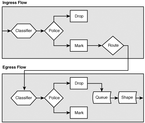
The classification of IP packets on the 5-tuple described previously is easily accomplished on unencrypted traffic, although IPSec presents a challenge to packet classification. As you saw in Chapter 2, “IPSec Overview,” IPSec headers may mask the original IP packet header information such as protocol identifiers and source and destination port numbers. We know that the IPSec process will encapsulate the original IP header (tunnel mode) with a newIP header or add an IPSec header behind the original IP header (transport mode). In the process, the protocol identifiers and port numbers are replaced with IPSec protocols and ports. ESP uses the IP protocol ID of 50, and AH uses 51. The IKE protocol uses IP protocol ID 17 (that is, UDP) with port number 500. Finally, IPsec Network Address Translation–Transparency (NAT-T) also uses UDP encapsulation with port number 4500 as a means to provide IPsec establishment through NAT gateways. The only remaining QoS attributes available following encryption are the DSCP bits identified in the IKE, ESP, NAT-T, or AH IP header.
Note that the IPSec standard specifies the automatic preservation of the DSCP bits in the original IP packet. As such, the original IP header’s DSCP must be present in the IPSec packet’s IP header. Keeping that in mind, you will review the three most common encapsulation models including IPSec transport mode, IPSec tunnel mode, and IPSec protection of GRE, and explore the implications for packet classification.
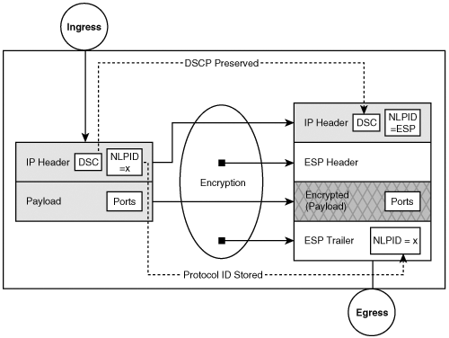
You may recall from Chapter 2, “IPSec Overview,” that IPSec transport mode is typically applied to traffic that originates or terminates on the router itself. Recall that in transport mode the source and destination address fields in the original IP header are intact, but the protocol identifiers from the original IP header are in the IPSec trailer and the protocol identifier in the original packet is replaced with that of IPSec (50 or 51). As such, access to the original protocol identifier and ports becomes inaccessible to the QoS classification mechanisms applied on the IPSec egress interface and any router between the IPSec endpoints. Because the original IP addresses are not encapsulated, they may continue to be used as classifiers for IP QoS. Likewise, the DSCP are preserved in the IP header. Figure 8-2 highlights the typical QoS attributes that are masked and those that remain after IPSec transport mode encapsulation.
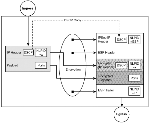
In contrast to IPSec transport mode, you learned that with the IPSec tunnel mode, the original IP packet is encapsulated with a new IP header; therefore, all of the original QoS attributes in the IP header (that is, the IP addresses, protocols, and ports) are lost, with the exception of DSCP, which must be copied into the encapsulating IPSec header. None of these lost attributes can be used for classification by the router on the IPSec egress interface or any router between the IPSec endpoints. Figure 8-3 highlights the typical QoS attributes that are masked and those that remain after IPSec tunnel mode encapsulation. Note also the disposition of the protocol identifier (Proto ID) from the original packet to the encrypted packet.
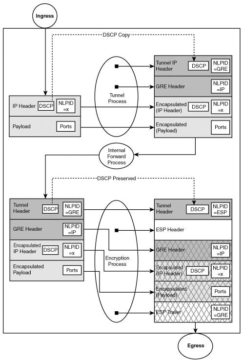
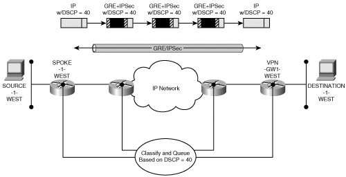
With IPSec-protected GRE, the original IP packet is first encapsulated during the GRE process. Of course, similar to the IPSec tunnel mode, the entire original IP packet is encapsulated, hiding the original QoS attributes (addresses, protocols, and ports). The new GRE IP header should copy the DSCP field; however, the protocol will change to protocol ID 47 and the IP addresses will be specified by the GRE encapsulation process. Next, the GRE IP packet must pass through the IPSec encapsulation process defined previously. Clearly, the IPSec process will only be able to preserve the QoS attributes specified in the GRE IP header (that is, addresses and DSCP for transport mode, DSCP for tunnel mode, and GRE protocol ID if qos pre-classify is used). Figure 8-4 highlights the protocol attributes typically used for QoS, and shows those that are encrypted or hidden as well as those that remain accessible to QoS processing after IPSec transport mode encapsulation of GRE tunnels.
Note
Note that qos pre-classify may be applied to the tunnel interface as well. Doing so allows the original IP packet’s attributes to be available for subsequent crypto and QoS processing. These attributes are only available to the processes on the encrypting gateway. Any QoS functions between the encrypting and decrypting gateways will not have access to this information;therefore, it’s imperative that the DSCP be marked appropriately for consistent application of QoS tools.
In this scenario, the only persistent QoS attribute is the DSCP from the original IP header. Again, this emphasizes the importance of classifying and marking an unencrypted packet’s DSCP prior to incurring any encapsulation (GRE or IPSec) as the pre-classification and marking dramatically simplifies the QoS models required to provide end-to-end QoS. Assuming the unencrypted traffic is properly marked, the same QoS classification and queuing mechanisms may be used in the sub-networks prior to encryption, those after encryption, and those after decryption. Figure 8-5 demonstrates the value of the transitive nature of the DSCP.
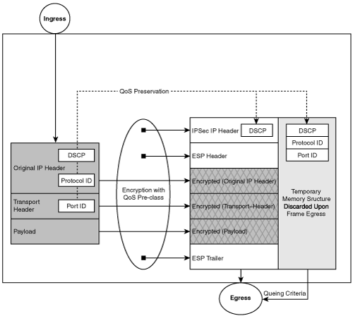
To reconcile the loss of information during the IPSec encapsulation process, Cisco has implemented a special QoS mechanism referred to as qos pre-classify (described previously). With this feature, the original IP packet’s attributes (addresses, protocol, ports, DSCP) are copied to the IPSec-encapsulated packet as it moves to the egress queue. When classification methods are applied to the egress interface, the IP QoS mechanisms will use the copied original IP packet QoS attributes as opposed to the encapsulating IPSec header. This model allows the designer to build queue structures that may queue packets based on the original addresses, protocols, and ports. The copied information is simply discarded as the packet leaves the router. Figure 8-6 demonstrates how the gateway performing encryption may leverage additional attributes of the packet for classification.
Of course, any interim router processing the packet between the two IPSec endpoints will not have access to the same QoS attributes as the encrypting gateway. All the interim routers will still have access to the DSCP bits in the IPSec encapsulated packet which were copied from the original IP packet and preserved. Therefore, it is a best practice to set the DSCP bits as close to the original host as possible. Doing so allows a consistent packet classification end-to-end.
Table 8-1 highlights the parameters that are preserved by the encryption and encapsulation processes. Although some of the attributes used for QoS are available on the encrypting router, the only attribute that is consistently available between the encrypting and decrypting routers is the set of DSCP values.
The introduction of IPSec encryption (or IPSec protection of GRE encapsulation) may significantly affect the queuing model used to provide quality of service. It is worthwhile to focus on the implications of IPSec on queue structures and bandwidth allocations. Of particular interest is the size of the packets as they go through the encryption or encapsulation processes.
Chapter 2, “IPSec Overview,” described the impact of IPSec encapsulation on the MTU. It is evident that the process of encapsulating and fragmenting packets may dramatically change the probability distribution for various packet sizes. The observed packet size distribution used on an unencrypted FR interface may be quite different on an IPSec-protected interface; therefore, careful consideration must be given to buffer allocations assigned to class queues as well as system buffers. As an example, assume a simplified data traffic flow with a packet size distribution ratio of 4-7-4 for 40-, 512-, and 1500-byte packets, respectively. If we pass this packet stream into an IPSec-protected GRE tunnel where the GRE MTU is specified as 1400 bytes, the packet size distribution will change due to packet fragmentation to a ratio of 4-7-4-4 with packet sizes of 40, 512, 100, and 1400 bytes, respectively. Note that the frequency of small packets (those less than 104 bytes applicable to the system’s small buffers) is doubled. Likewise, the class queue structure and buffers allocated to each class may need to be adapted from the default 64 packets to handle the modified packet distribution.
Another interesting challenge with IPSec encapsulation is the assignment of bandwidth parameters associated with QoS policies applied to interfaces. Obviously, the encapsulation overhead of IPSec and GRE will increase the number of bits per second that must pass through an interface. A common error made by designers is to assess gateway QoS requirements based on the application’s bandwidth (that is, VoIP bearer bit rates), but fail to consider the additional bandwidth that encryption and encapsulation add to the flows at the encrypting router. The issue is particularly relevant on low-speed interfaces and traffic flows with a high concentration of small packets.
The appropriate solution to this problem is to set the QoS bandwidth allocation to a value higher than the actual application bandwidth requirements such that the post-encrypted flow approaches the actual bandwidth assigned to the application’s queue. Again, the traffic application’s expected packet size distribution profile is necessary to estimate the percentage of overhead required on a particular interface. A low-speed interface will be much more susceptible to congestion; hence, the ramifications of IPSec on QoS are much more severe on low-speed interfaces. Likewise, traffic flows dominated by VoIP will incur a large percentage of overhead due to the small packet size of VoIP frames. Now, you’ll explore some of the intricacies of running VoIP flows through IPSec VPN connections.
It is becoming increasingly important for enterprises that build IPSec VPNs to deliver voice services over the VPN. Voice over IP in itself brings unique challenges; adding IPSec complicates this further. The most critical network characteristics that need to be considered for a successful voice over IP deployment are delay, jitter, availability, and packet loss.
The generally accepted International Telecommunication Union (ITU) value for one-way delay is considered to be 150msec. In a circuit-switched paradigm, this requirement is easily achieved except for in the most extreme cases such as satellite relays. A packet-switched network may push the delay for a packet flow well over 150msec. In fact, it’s not uncommon for a congested IP network to experience delays exceeding 1 or 2 seconds. End-to-end packet delay can be attributed to delays due to switching, queuing, serialization, or propagation.
Switching is the function of receiving an IP packet and making a decision regarding which output interface to switch the packet to. In most modern IP routers, the switching delay for IP packets is a few micro or nanoseconds, and therefore almost a non-issue. Note, however, that because IPSec does increase switching delay, it may be important to consider when dealing with applications like voice—especially when IPSec encryption and decryption is done in software. For applications such as voice that have a stringent budget on end-to-end delay, the use of hardware-assisted encryption and decryption is recommended. Hardware-assisted encryption and decryption will minimize encryption delays mitigating the impact to the end-to-end voice delay budget. Nevertheless, the hardware-accelerated encryption/decryption processes do add several milliseconds to the delay, which must be considered in the delay budget.
Once the switching decision has been made, the packet is queued for transmission out a physical link. At this point, it is possible to have queuing delay. On an interface that is not very busy or not congested, queuing delay may not be very significant and the default FIFO queuing scheme will suffice. Queuing delay becomes very significant when traffic bursts egress the outbound interface, making the interface congested and thereby causing outbound queues to build up. A priority queuing mechanism such as Low-Latency Queuing (LLQ) should be applied to voice traffic to protect from queuing delays. Typically, voice packets are classified into the priority queue based on DSCP bits in the IP header. As mentioned previously, the original IP packet’s DSCP bits are copied into the IPSec IP header; therefore, classification and priority queuing of voice traffic can be performed at the encrypting end of the IPSec tunnel endpoint without a problem. Of course, implementing LLQ of voice traffic end-to-end along each hop is recommended.
All the queuing mechanisms are applied to packets queued on the outbound interface. At the head end of the IPSec tunnel (where packets that match the IPSec policy are encrypted), the encryption engine may only have a first-in, first-out (FIFO) queue. The encryption engine with a FIFO queue will not distinguish between the data and voice packets. It is possible for a low priority data flow to congest the encryption engine. Although queue management on the outbound interface uses LLQ to handle voice, it is negated by the FIFO queue in the encryption engine. Cisco IOS version 12.2(15)T introduced a new feature that adds LLQ at the crypto engine. There is no configuration required to enable this feature; it is enabled by the QoS service on the output interface. This feature is available only with the hardware encryption engine and not with software encryption—another reason to use hardware-assisted encryption for voice over IPSec. Note that it is still possible to congest the LLQ on the encryption engine. Certain applications (for example, multicast and routing updates in GRE tunnels) will present a flood of replicated traffic to the crypto engine. If this traffic is high-priority and queued on the crypto engines LLQ, then congestion may occur, causing loss.
Once the packet is queued for transmission on the output link, serialization delay comes into the picture. All circuits have a common characteristic known as serialization delay, which represents the time it takes some unit of data to be serialized onto the circuit. The delay is directly related to the length of the packet, the bandwidth of the circuit, and the framing technology employed. For instance, the serialization delay for sending a 1500-byte HDLC-encapsulated packet on a 45Mbps circuit will be:
Serialization delay at low-speed links can contribute significantly to the end-to-end voice delay budget. Voice-over-IP packets are much smaller in size than a 1500-byte data packet. For example, on a 56Kbps leased line link where voice and data traffic coexist, a voice packet may be enqueued to transmit just when a 1500-byte data packet starts transmission (that is, serialization) over the link. Now, there’s a problem. The delay-sensitive voice packet will have to wait 214 msec before being transmitted due to the serialization delay for the 1500-byte packet. Fragmenting these large data packets into smaller ones and interleaving voice packets among the fragments reduces the delay and jitter. The Cisco IOS feature Link Fragmentation and Interleaving (LFI) can be configured to do this fragmentation.
Note
LFI is required only on slow-speed interfaces. The recommendation is to use this feature on interfaces whose bandwidth is less than 768kbps.
Alternatively, you may apply a much smaller MTU on GRE tunnel interfaces such that you induce host fragmentation where possible and fragment IP packets prior to encryption, accordingly.
The last delay attribute is called propagation delay. This is simply the time between the completion of data transmission at the application sender and data reception at the other end by the application receiver. This attribute is going to be dictated by the length of the medium and speed of signal propagation in that medium.
Jitter is the variance in the arrival interval of a stream of packets. Clearly, a VoIP encoder will generate a constant stream of voice-encoded packets with a defined constant interval between successive packets. Once these packets traverse the packet-switched network, the delays mentioned previously create variability in the arrival interval of the VoIP packets. To accommodate the jitter, a jitter buffer is used to collect the VoIP packets with a minimally induced delay. This allows the voice decoder to continuously play out the voice stream with no drops.
Typically, the jitter buffer will be adaptive with the induced delay starting at a default value such as 20msec. The jitter buffer will attempt to reduce the induced delay if the network demonstrates consistent packet inter-arrival times or increase the induced delay to perhaps 50msec if the network experiences severe congestion and jitter. Scheduling voice packets into the priority queues through the network minimizes the jitter experienced by VoIP packets as they traverse the network. The IPSec encryption and decryption process may induce a negligible amount of jitter; therefore, designers rely on the continuity of the DSCP before, during, and after the encryption/decryption processes at the two endpoints in order to minimize the jitter induced by the network. Typically, a well-managed backbone network will demonstrate no more than 2msec of jitter and may approach jitter values as low as 100usec.
An extensive amount of research on VoIP’s sensitivity to loss has demonstrated that packet loss exceeding one percent of the VoIP data stream will be apparent to end users. It is apparent that the network must preserve the VoIP stream, especially in congested points in the network such as access links. The use of priority queuing on VoIP-encrypted packets allows the VoIP packets to pass through the congested links with minimal loss. Generally, voice and data packets will be passing between two crypto gateways using the same security association. The voice packets are typically identified by a DSCP setting of Explicit Forwarding (EF) while data packets will use one of the Assured Forwarding (AF) DSCP settings. The queue systems that come into play after encryption between the crypto gateways will use the DSCP values to prioritize the voice packets ahead of the data packets.
The ramification of scheduling VoIP packets ahead of other data packets in the same IPSec SA is that the sequence of packets arriving at the decryption device is out of order. By default, IPSec will use a 64-packet anti-replay window to detect packets that are potentially replay attacks. We’ll assume the crypto gateway has received crypto packet with sequence number N. The gateway will now accept any valid crypto packet with a sequence number between N-64 and N. Packets that arrive with a sequence number less than the N-64 violate the anti-replay window. Such packets are assumed to be replay attacks by IPSec and are dropped. With a substantial volume of VoIP-encrypted traffic passing through a congested interface, we mitigate packet delay of the voice streams while inducing latency or loss in the other data streams that use the same IPSec SA. If the encrypted data packets of an SA are sufficiently delayed relative to the voice packets, the data packets may violate the anti-replay window while the voice packets are accepted.
There are two means of mitigating the loss to data streams in a combined voice/data encrypted flow. First, the link capacity may be increased, or more bandwidth may be made available to the data packets in the combined voice/data flow. The additional schedule time available to the data flow decreases the probability of a data packet being delayed beyond the 64-packet window. The second alternative is to increase the anti-replay window. Preliminary testing of this feature indicates that an anti-replay window of 1000 packets is sufficient to mitigate frame loss due to anti-replay violations.
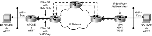
An alternative to the combined voice/data flow is to create two IPSec proxy policies that specifically put voice into one IPSec SA and place data in a second IPSec SA. The intermediate queuing systems that delay the data packets and forward the voice packets do not change the order of voice or data packets with respect to their individual IPSec SA anti-replay sequence. This approach is acceptable for native IPSec encryption processes; however, this is less feasible inGRE-tunneled scenarios. The native IPSec proxy may select unique IPSec SAs by referring to the QoS attributes of the original packet. The use of IPSec-protected GRE performs GRE encapsulation prior to presenting the encapsulated data to the IPSec encryption processes. The GRE packet has no criteria available to distinguish between the VoIP and data because the original IP addresses, protocol, and ports are hidden. The IPSec proxy cannot use the DSCP values as criteria for creating unique IPSec SAs. The GRE encapsulation process typically uses the same IP source address, destination address, and protocol ID for all encrypted flows between the gateways. The result is the establishment of a single IPSec SA.
The only way to avoid this is to use the parallel GRE tunnels with unique source and destination tunnel endpoints that correlate with unique IPSec proxy statements. The unique tunnel source or destination IP addresses allow IPSec to establish distinct voice and data IPSec SAs for VoIP and data flows, respectively.
Most network architects find that combining voice and data flows into a single IPSec SA is preferred over splitting voice and data into separate IPSec SAs. The combined voice and data flow saves on the number of IPSec SAs deployed, which improves network scalability. In addition, the routing of voice and data into separate IPSec-protected GRE SA streams becomes quite complicated. Likewise, maintaining distinct IPSec proxies for voice and data streams becomes quite an onerous provisioning task. In general, it’s best to traffic engineer the links such that prioritized VoIP traffic will not exhaust the queuing resources or eliminate scheduling time for the data queues.
By using VoIP traffic engineering best practices (that is, by limiting voice streams to less than 33% of the link bandwidth) and ensuring that the combined voice/data flow does not exceed 70% of link utilization, the combined flow of VoIP and data rarely experiences anti-replay loss. Should the operator continue to experience loss due to anti-replay violations, the recommendation is to increase the anti-replay window. A typical voice stream will generate roughly 50 packets per second (that is, 20msec voice-sampling interval). Increasing the anti-replay window from 64 packets to 1000 packets has minimal impact on the security risk of the system. The anti-replay time interval for a single voice flow increases from 1.28 seconds (64 packets divided by 50 packets per second) to 20 seconds (1000 packets divided by 50 packets per second), assuming no other traffic is passing through the IPSec SA which is rarely the case. The IPSec SA is usually carrying a variety of traffic types at a packet-forwarding rate that makes the anti-replay interval short enough to mitigate all but the most determined attacker.
You saw in Chapter 5, “IPSec VPN Architectures,” various topological options for the deployment of IPSec VPNs. The previous section defined various implications of running voice applications in IPSec. The large-scale introduction of voice applications on a network has serious ramifications for the viability of designing, building, and managing IPSec VPNs. In this section, we will explore the impact of accommodating VoIP in the various VPN architectures.
First, you should consider whether VoIP must be encrypted at all. From a routing perspective, it is much easier to treat all VoIP traffic as high priority data traffic over a single routing topology. The converged voice and data topology must simply handle the traffic classes appropriately through the queuing mechanisms discussed previously. Many organizations are evolving their VoIP communication systems to use end-to-end bearer encryption based on Secure Real Time Protocol (SRTP). In this case, encryption of VoIP traffic with IPSec is redundant. Some organizations have chosen to exclude SRTP VoIP traffic from the IPSec topology. There are two common methods for achieving this architecture.
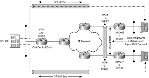
The first method uses IPSec proxy policies that exclude VoIP traffic. Recall that the IPSec tunneling methods essentially direct encrypted traffic to the peer gateway. Routing decisions in the backbone for data traffic will be based on the IPSec tunnel addresses, whereas routing decisions for VoIP traffic will be based on the bearer endpoint addresses. Essentially, there are two routing topologies and traffic matrices—one for voice flows and the other for data. Figure 8-7 shows the disjointed VoIP and data topologies.
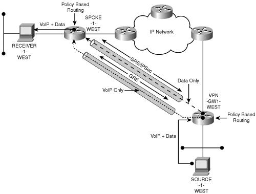
The second method uses an explicitly defined overlay topology using GRE tunnels. Essentially, a VoIP GRE overlay topology is built in which the GRE tunnel addresses are excluded from the IPSec policy. A separate data GRE topology is built in which the GRE tunnel addresses are included in the IPSec policy. Now we can use Policy Based Routing (PBR) in the VPN gateway to route the VoIP streams into the unencrypted GRE topology while routing the data streams into the encrypted GRE topology. The VoIP bearers and data streams from end users typically use the same source and destination IP address space; therefore, the PBR must vector the appropriate packets into the disjoint VoIP and data tunnel overlay topologies using protocol and port identifiers.
Note
The whole point of VoIP is to leverage voice and data services in a synergistic manner. Although it is possible to use a distinct VoIP endpoint address space, doing so typically defeats one of the primary motivations for using VoIP technologies—integrated voice and data applications.
Figure 8-8 shows how the two GRE topologies are defined and where the PBR functions are applied.
Note
The IPSec proxy configured on the VPN gateways must be able to distinguish between the data GRE tunnel and the VoIP GRE tunnel. Because there are no source or destination ports and the protocol ID is always the same, the IPSec proxy must use a unique IP address on one of tunnel endpoints. Generally, it is easiest to configure two GRE tunnel endpoints on the hub—one that is used for data tunnels and one that is used for VoIP tunnels. Doing so allows the IPSec proxy on both the hub and spoke to uniquely identify the data GRE tunnels.
The explicit VoIP exclusion techniques (for example, PBR or IPSec proxy) usually become unwieldy in large VPN topologies. It is also difficult to accommodate fault-tolerant architectures using the static configuration techniques. As a result, most customers elect to use a convergent topology for voice and data to simplify their network architecture, traffic engineering, and fault-tolerance models. Therefore, this chapter focuses on these convergent VoIP and data architectures.
In the ideal scenario, designers are able to architect the network according to a known set of design constraints. Provided the service provider or backbone operator has adequately characterized the IP network (for example, it may be Multi-Service CPN certified), designing the VoIP topology and QoS control mechanisms is relatively straightforward. Unfortunately, the same cannot be said for remote access networks in which multiple providers are involved and QoS attributes are rarely honored, much less preserved. Clearly, the network between the two IPSec endpoints (the IPSec client and the Concentrator) must be characterized as best-effort and treated as such.
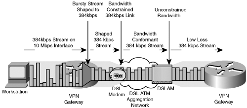
Nevertheless, you can mitigate certain problems by controlling the flow of traffic at the IPSec endpoints. One aspect where VoIP call characteristics can be improved is through traffic-shaping techniques. We must assume that the IP path between the two IPSec endpoints has no support for QoS. One critical piece of information is the maximum bandwidth available. For example, a remote access user may have a DSL circuit with a maximum of 640kbps downstream and 384kbps upstream. We can improve our packet loss performance by shaping our VoIP and data stream into the maximum bandwidth available such that we avoid loss. Naturally, you want the VoIP stream to have the highest chance of success. By shaping the combined stream to not exceed 640kbps downstream and 384kbps upstream and prioritizing the VoIP stream over the data stream (preferably prior to encryption), you preclude the low bandwidth remote access network link from indiscriminately discarding voice or data. Figure 8-9 demonstrates the optimal shaping, queuing, and scheduling of the VoIP and IPSec flow on a remote access link.
Site-to-site architectures for an IPSec VPN commonly use GRE tunnels protected by IPSec. Applying QoS policies to a tunnel interface that is an abstract interface can be challenging, as it is possible that the encrypted packet flow may be switched out to a high-speed or low-speed link. Obviously, you can assign a queue structure to any of the VPN gateway’s physical interfaces, allowing the queues to be defined relative to the physical bandwidth. The tunnel interface QoS structure has no adaptive knowledge of which interface is actually in use; therefore, a hierarchical queue structure is required with explicit bandwidth statements in order to use shaping or bandwidth percentage-based queue structures.
Of course, the bandwidth applied to the tunnel interface may not match the physical interface that the tunnel uses to reach the peer. The principle advantage of applying QoS to the tunnel interface is that the packet order for a set of streams to the same peer is defined, scheduled, and queued prior to encryption. Reordering packets on entry into the tunnel interface forces the VoIP traffic to precede the data traffic upon leaving the VPN gateway. Once the data is encrypted, intermediate nodes between the VPN gateways may reorder packets of the tunnel when congestion occurs; therefore, anti-replay drops may still be a factor. This is a principle disadvantage of IPSec over GRE. There is a single IPSec SA defined for the aggregate set of streams in the GRE tunnel. One effective way to mitigate the anti-replay drops is to set the bandwidth of the GRE tunnel’s queue structure to the slowest link between the tunnel peers. Example 8-1 shows a configuration model in which the QoS mechanism uses a parent policy to shape the traffic according to the slowest link while prioritizing the VoIP ahead of the data traffic.
Example 8-1. Hierarchical Shaping of VoIP and Data Prior to Encryption
spoke-2-west# show configuration
...
policy-map vpn
  class control
   bandwidth percent 5
  class mmoip
   priority percent 30
  class data
   bandwidth percent 63
...
policy-map gre-qos
  class shape-t1
   shape average 1464000
   service-policy vpn
...
class-map match-all shape-t1
  match any
class-map match-all data
  match ip precedence 0  1  2  3
class-map match-all control
  match ip precedence 6  7
class-map match-all mmoip
  match ip precedence 4  5
...
interface Tunnel1
 ip address 9.0.0.2 255.255.255.252
 ip pim sparse-mode
 service-policy output gre-qos
 tunnel source 9.1.1.134
 tunnel destination 9.1.1.10
 tunnel protection ipsec profile spoke-2-west
...
end
You see that we have two service policies: vpn and gre-qos. The gre-qos service policy is applied to the tunnel interface such that any traffic entering the tunnel conforms to the average bandwidth rate of 1.46Mbps (assuming that the constrained bandwidth available to this site is consistent with a T1). With the traffic shaped to fit inside a T1, we prioritize our VPN traffic such that MultiMedia over IP (mmoip) is scheduled first and set to not exceed 30% of the shaped capacity. We have also guaranteed control traffic, or routing protocols, 5% of the bandwidth with data traffic essentially obtaining the rest. Also, note that we have selected the precedence bits (a component of the DSCP) as the matching criteria. Next, you’ll see the implications of QoS when applied to the IPSec architecture.
As you saw in Chapter 5, “IPSec VPN Architectures,” the hub-and-spoke topology is one of the most widely deployed IPSec VPN architectures. In this topology, all spoke-to-spoke communication (including VoIP) transits via the hub. The introduction of a hub transit point to the VoIP bearer stream needs to be accounted for in the traffic engineering and voice delay budget. Having spoke-to-spoke VoIP traffic hair-pinning through the IPSec hub, wherein the hub has to decrypt the VoIP traffic it receives from the spoke and encrypt the traffic again to the spoke the traffic is destined to, may significantly impact the performance of the network. First, the packet size distribution will be radically altered through the IPSec VPN connections. The substantial increase in forwarding requirements for the increased percentage of small packets may consume an inordinate amount of packet processing resources on the IPSec VPN hub. Second, the underlying IP network queue schedulers must be altered to accommodate the traffic engineering of the transient IPSec-protected VoIP stream. Figure 8-10 shows the implications for these two fundamental changes in the network architecture.

The introduction of redundant hubs in the topology further complicates the traffic engineering challenge. One obvious alternative to the hub-and-spoke architecture is to build a full-mesh architecture. Of course, eliminating the transient decryption, routing, and encryption through a hub doesn’t come for free. Chapter 6, “Designing Fault-Tolerant IPSec VPNs,” outlined the provisioning and operational costs associated with building a full-mesh IPSec VPN. The tradeoff between optimal traffic engineering and IPSec configuration complexity will likely be driven by the probability of VoIP calls being established between branch sites. The complexity of the full-mesh IPSec VPN may not be justified if the percentage of site-to-site calls is rather low. As a result, most enterprises chose to use a hub-and-spoke topology for all communications.
An alternative to the static full mesh is the DMVPN architecture. The main advantages of the DMVPN architecture are reduced configuration complexity and the ability to build temporary direct spoke-to-spoke connections on demand. The feasibility of using a temporal full mesh may be mitigated by the delay associated with the IKE and IPSec SA establishment between spokes. The transaction delay for establishing the IPSec SA is substantial. Assuming the VoIP call-control follows a different path than the bearer path, you are likely to run into a delayed talk interval following the completion of call setup, but prior to completion of the IPSec SA that carries the bearer.
The only way to mitigate the delayed talk interval is to either reduce the IPSec SA establishment intervals through accelerated IKE and IPSec SA establishment, temporarily route the bearer through the hub, or induce post-dial delay.
The DMVPN architecture allows spoke-to-spoke traffic to transit via the hub while waiting for the spoke-to-spoke IPSec process to complete. Doing so avoids the post-dial-delay and dead-talk interval following a call-connect by allowing the traffic to transit the hub. Once the IPSec session is established directly between the spokes, the VoIP flow will transition to direct connection following a more expeditious route. The drawback to this solution is that the jitter buffers in the VoIP endpoints are synchronized with the delay associated with traffic transiting the hub. The completion of the shorter IPSec/GRE path causes VoIP traffic to arrive early at both receivers. The VoIP jitter buffers must advance the play out, causing a glitch in the audio. Fortunately, this scenario only occurs when a VoIP call is causing the spoke-to-spoke connection establishment. If the spoke-to-spoke connection exists prior to call-connect, then the VoIP bearer will take the shortest path at the time of call-connect.
The alternative to transitioning VoIP bearers from the non-optimal path to the optimal path is to force the VoIP to take the optimal path during the call-connection establishment. Post-dial delay may be induced by waiting for an RSVP path reservation to complete via the encrypted bearer path. The RSVP processes kick off the establishment of the IPSec SA prior to allowing the call-connect. The RSVP RESV message requires the direct spoke-to-spoke connection to be established prior to proceeding with the subsequent stages of call-connect. By the time an operator initiates a discussion, the IPSec spoke-to-spoke connection has already been established. This discussion highlights the importance of synchronizing the VoIP call-control and bearer paths with the IPSec VPN topology.
You have seen it demonstrated that designing VoIP to operate within an IPSec VPN is certainly possible by accounting for the anomalies created by the IPSec connection model. The usual VoIP bandwidth and delay attributes must be considered while also accommodating IPSec VPN topology, anti-replay windows, and IPSec overhead.
Applications that use IP multicast are becoming increasingly important to many enterprises. They range from file and software updates, to video broadcasts, to multi-party conferencing and many other applications. In this section, you will explore how IPSec VPN handles multicast. Multicast applications typically rely on a combination of unicast routing protocols and multicast routing protocols. The current IPSec standards (for example, RFC 2401 through 2410) do not support IP multicast over native IPSec tunnels, although extensive research is in progress in the IETF under the auspices of the MSEC working group for Multicast Security.
As of this writing, the only choices available are for carrying multicast traffic over an IPSec VPN. The first is to use virtual IPSec interfaces with an IPSec proxy of SOURCE: ANY, DESTINATION: ANY. This approach requires each virtual IPSec interface to have an explicitly defined peer. The second approach is to use tunnels between VPN sites and use IPSec to encrypt the tunnel. Cisco currently leverages the IPSec protection of GRE tunnels to accommodate multicast; however, a forthcoming interface model using a virtual IPSec interface will effectively achieve the same goal. As you saw in Chapter 2, “IPSec Overview,” IPSec protection of GRE between the VPN sites performs encapsulation in GRE that results in a unicast frame. The multicast traffic between sites is merely payload for the GRE tunnel that is protected by IPSec. The multicast processes are associated with the tunnel interfaces and hidden from the underlying IPSec processes.
The most common reason for deploying IPSec VPNs over GRE tunnels is to support dynamic routing protocols between sites of the VPN that use IP multicast such as EIGRP and OSPF. Most multicast applications are essentially point-to-multipoint where there is a single source and many receivers. Clearly, the hub-and-spoke network architecture shown in Figure 8-12 will serve this application well, assuming that the source of the multicast traffic is co-located with the hub.

The configuration of multicast on hub-and-spoke topology is shown in Example 8-2. The configuration of a basic multicast capability on IOS is rather simple. It is important to understand that most multicast protocols rely upon the router’s existing routing topology forwarding information base (FIB) derived from protocols such as IGP and BGP. Multicast protocols such Protocol Independent Multicast (PIM) use the FIB to determine where to send multicast join messages based on Reverse Path Forwarding (RPF), which is the shortest path back to the source. First, you’ll need to enable multicast globally on the router, then you’ll need to enable multicast on each of the eligible interfaces (that is, GRE tunnel interfaces). In this case, simply enable multicast on the tunnel interfaces at the hub-and-spoke VPN gateways. PIM sparse mode (PIM-SM) has been configured on the GRE tunnel interface in our example. PIM dense mode (PIM-DM) could also be used as the multicast adjacency protocol, but it is not recommended because dense mode will send multicast traffic to a site irrespective of whether the site has receivers.
Example 8-2. Multicast Configuration on GRE/IPSec Spoke
vpn-gw1-west#show run interface Tunnel 1
interface Tunnel1
 description Tunnel to spoke-1-west
 ip address 10.2.2.1 255.255.255.252
 ip pim sparse-mode
 tunnel source 9.1.1.10
 tunnel destination 9.1.1.22
 tunnel protection ipsec profile gre
vpn-gw1-west#show run interface Tunnel 2
interface Tunnel2
 description Tunnel to spoke-2-west
 ip address 10.2.2.5 255.255.255.252
 ip pim sparse-mode
 tunnel source 9.1.1.10
 tunnel destination 9.1.1.138
 tunnel protection ipsec profile gre
vpn-gw1-west# show run interface FastEthernet0/1
interface FastEthernet0/1
 description VPN RP interface
 ip address 10.1.1.1 255.255.255.0
 ip pim sparse-dense-mode
In this configuration, the hub’s Ethernet interface (10.1.1.1) has been designated as the rendezvous point (RP) for the Multicast VPN.
The topology assumes the hub router does the multicast replication. This places a significant burden on the hub router as it must perform IPSec protection, GRE encapsulation/decapsulation, manage the routing protocol on each GRE tunnel interface, and replicate multicast frames across each tunnel serving a downstream multicast receiver. The combination of these functions typically limits the scalability of the network due to processing constraints at the hub. In order to alleviate the burden of replicating and forwarding multicast streams on the VPN hub, some VPN architectures leverage the spoke-to-spoke topology of the GRE/IPSec tunnels in order to conserve packet processing resources at the hub site. Assume that a full-mesh IPSec VPN is justified between the potential multicast application participants. In that case, we would build a full-mesh IP tunneled network where each IP tunnel is encrypted with IPSec.
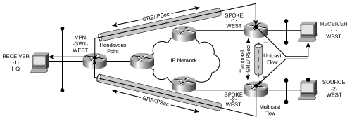
The set of full-mesh IP tunnels may be established in one of two ways. The first approach is to statically build an IP/GRE tunnel between each VPN gateway serving a multicast endpoint. A statically configured IPSec proxy builds an SA that encrypts the associated IPSec/GRE tunnel. The GRE/IPSec tunnels will establish an IPSec connection between the spokes only if there is data that must pass over the tunnel. Some designers may be tempted to build GRE/IPSec tunnels with static routing and no keepalives between the spokes in order to minimize the number of active GRE/IPSec connections on each spoke. However, once you configure multicast on the GRE tunnel interface, the multicast processes attempt to find peers capable of multicast adjacencies. Adjacencies are built by multicasting Hello messages on each multicast-enabled interface to identify potential peers as described in RFC 2362. Once the peers are established, an adjacency is sustained by periodic Hello messages. Figure 8-13 provides an example in which the network architecture leverages spoke-to-spoke use of GRE/IPSec tunnels to mitigate the transient traffic at the hub site.

The multicast adjacency process sustains every GRE/IPSec tunnel to validate that link as a viable path. If resource conservation was a primary concern at any of the GRE/IPSec nodes, then the multicast Hello protocol just violated that assumption because every possible GRE/IPSec path is established. The PIM-SM avoids sending multicast streams until receiving explicit joins whereas the PIM-DM multicast processes prune back the multicast flows to the minimal distribution tree required. Nevertheless, both dense- and sparse-mode multicast use multicast Hello packets to sustain neighbors.
The requirement to build a static GRE/IPSec tunnel for each potential multicast peer obviously limits the scalability of the architecture. Every spoke must participate in PIM Hello exchanges with every other spoke; therefore, every GRE/IPSec tunnel will be active in order to maintain the PIM adjacencies. Scalability is further constrained by the fact that each spoke must establish its multicast peers simultaneously upon booting. Obviously, we need to find more efficient topologies for multicast.
In this scenario, the configuration of multicast on the GRE tunnel interfaces forces the establishment of all the GRE/IPSec tunnels. Each spoke has assumed the role of a “hub” in this persistent full mesh. Perhaps the spoke has sufficient resources to manage the persistent full mesh; however, that is rarely the case as the VPN becomes sufficiently large. If you look at the state of a spoke before and after the application of multicast routing, you can see that all of the GRE/IPSec tunnels transition to an active state. Example 8-3 shows the configuration of the spoke used in the GRE/IPSec full mesh with the addition of multicast routing.
Example 8-3. Spoke GRE/IPSec Temporal Full Mesh
spoke-1-west#show run interface tunnel 1
interface Tunnel1
 description Tunnel to vpn-gw1-west
 ip address 10.2.2.2 255.255.255.252
 ip pim sparse-mode
 tunnel source 9.1.1.22
 tunnel destination 9.1.1.10
tunnel protection ipsec profile dmvpn


spoke-1-west#show run interface tunnel 2
interface Tunnel2
 ip address 10.2.2.9 255.255.255.252
 ip pim sparse-mode
 tunnel source 9.1.1.22
 tunnel destination 9.1.1.138
tunnel protection ipsec profile dmvpn


spoke-1-west#show run | include ip route
 ! Default route to the backbone
 ip route 0.0.0.0 0.0.0.0 9.1.1.21
 ! Generic route for VPN via Hub
 ip route 10.0.0.0 255.0.0.0 10.2.2.1
 ! Explicit route for VPN Subnet at spoke-2-west
 ip route 10.0.66.0 255.255.255.0 10.2.2.10
Example 8-4 shows the state of the GRE/IPSec tunnels once the multicast is applied.
Example 8-4. Spoke GRE/IPSec and Multicast State on Temporal Full Mesh
spoke-1-west#show ip pim neighbor
PIM Neighbor Table
Neighbor          Interface                 Uptime/Expires    Ver   DR
Address                                                             Prio/Mode
10.2.2.1          Tunnel1                   07:35:34/00:01:43 v2    1 / S
10.2.2.10         Tunnel2                   07:27:24/00:01:30 v2    1 / S
spoke-1-west#show crypto isakmp sa
dst             src             state           conn-id slot
9.1.1.22        9.1.1.138       QM_IDLE              27    0
9.1.1.10        9.1.1.22        QM_IDLE              19    0
You can see that the entire set of GRE tunnels will be active in order to pass multicast Hello packets. The example shows that Tunnel2 between SPOKE-1-WEST and SPOKE-2-WEST will remain active because the PIM process refreshes the neighbor adjacency every 30 seconds. The multicast process assesses every possible path to determine a path’s relevance to each potential multicast source. This places a tremendous burden on the CPE, especially in large full-mesh networks.
The full-mesh GRE/IPSec architecture obviously has serious constraints when applied in large networks. Recall from Chapter 7, “Auto-Configuration Architectures for Site-to-Site IPSec VPNs,” that the DMVPN architecture was designed to accommodate resource-constrained spokes in large temporal full-mesh networks. Next, you’ll consider the implications of applying the multicast process on the mGRE interface used in the DMVPN architecture.
At this point, you know that the GRE tunnels are capable of carrying multicast traffic such as OSPF and EIGRP routing protocols. When OSPF and EIGRP processes are assigned to the mGRE interface in DMVPN, you need to prevent the establishment of tunnels to all the spokes. Note that the configuration of the tunnel interface maps multicast traffic to the hub. Example 8-5 highlights the fact that the Next Hop Resolution Protocol (NHRP) will map any multicast traffic towards the NHRP server.
Example 8-5. Multicast Mapping on DMVPN Multipoint Interfaces
!
interface Tunnel0
 ip address 10.2.0.2 255.255.255.0
 no ip redirects
 ip mtu 1400
 ip pim sparse-mode
 ip nhrp authentication cisco
 ip nhrp map multicast 9.1.1.10
 ip nhrp map 10.2.0.1 9.1.1.10
 ip nhrp network-id 100
 ip nhrp holdtime 300
 ip nhrp nhs 9.1.1.10
 ip nhrp nhs 10.2.0.1
 ip ospf network broadcast
 ip ospf priority 0
 delay 1000
 tunnel source Serial1/0:0
 tunnel mode gre multipoint
 tunnel key 100
 tunnel protection ipsec profile dmvpn
end
The PIM process assigned to the multipoint interface uses multicast Hello packets to build the PIM adjacency. The multicast Hello is only directed to the hub; therefore, the spoke-to-spoke PIM adjacency is not established. The only time the spoke-to-spoke GRE tunnel is initiated is when unicast packets are sent. The architecture appears to be a temporal full mesh for unicast flows and a hub-and-spoke architecture for multicast flows. Figure 8-14 shows the flow topology for both multicast and unicast traffic in the DMVPN network.
Unfortunately, the dynamic establishment of spoke-to-spoke GRE/IPSec tunnels cannot be leveraged for multicast traffic. Nevertheless, the architecture scales reasonably well for large networks unless the hub is heavily burdened with multicast replication. Typically, multicast sources (for example, content servers) will reside at the hub site anyway; therefore, the multicast replication at the hub site is unavoidable. Of course, the hub will be burdened with routing adjacencies and IPSec peers in addition to the multicast replication.
Fortunately, the number of GRE/IPSec connections is minimized at the spoke. We do find at least one exception to this paradigm. When a spoke serves a multicast source, the receivers at the other spokes will force their spoke gateways to join the multicast tree using a unicast PIM Join message. This message will be sent directly between the spokes, forcing the establishment of the spoke-to-spoke GRE/IPSec connection. The spoke receiving the PIM Join for the multicast source will be able to forward multicast frames only into the multipoint tunnel that subsequently directs the multicast frames to the hub. From a scalability perspective, the spoke servicing a multicast source must be prepared for incoming GRE/IPSec connections from any spoke hosting a receiver of the multicast group. If the receivers are waiting for the multicast source, the spoke hosting the source is likely to receive simultaneous PIM Joins from many spokes hosting receivers. Effectively, the spoke becomes a GRE/IPSec hub for the multicast source and must be prepared to handle the simultaneous initialization of many incoming GRE/IPSec connections. Filtering PIM-SM joins to all sites except the hub prevents the simultaneous initiation of GRE/IPSec connections to a spoke hosting a multicast source. Because the multicast packets are forwarded only to the VPN hub site, the spoke is not burdened with multicast packet replication.
The previous sections addressed methods of “hiding” the multicast from the native IPSec processing through tunnels and virtual IPSec interfaces. The IETF has issued RFC 3740, “The Multicast Group Security Architecture,” as the reference for establishing native multicast security. The new architecture establishes the notion of a Group Security Association (GSA) that is valid among all the peers that belong to the same group. The GSA eliminates the necessity of establishing a full mesh of peer-to-peer relationships (tunnels, IKE, and IPSec SA) between the potential multicast source and destinations. The development of native multicast encryption methods will alleviate the requirement to “hide” the multicast frames from the encryption processes.
Note
The introduction of a GSA does not necessarily preclude the use of an IPSec SA at the same time. In fact, a GSA is a concept that includes all of the SAs for a group, which may include IPSec SAs.
The group security model is based on the premise that a source cannot know the intended recipient a priori. The potential sources and receivers must identify themselves as members of a group. Members of the same group are afforded a common level of trust such that they may exchange data between themselves. Next, you’ll examine how the members of a group are identified.
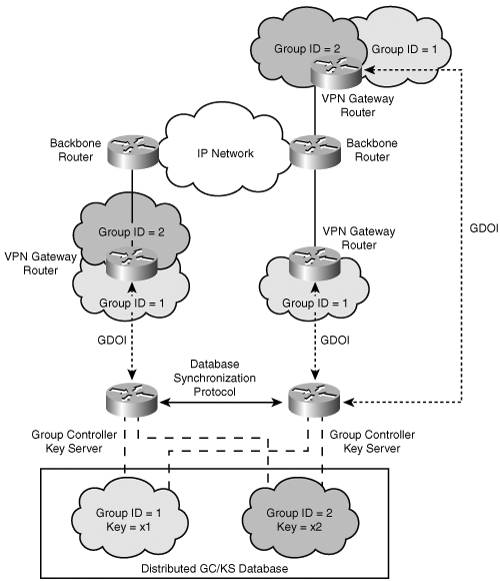
Each member of a security group is provided a set of credentials that allow the member to authenticate its right to join the group. To enable this process, a common reference point is needed, where all the members may convene. The Group Domain of Interpretation (GDOI) protocol (RFC 3547) defines the means for allowing a group member to authenticate with a Group Controller/Key Server (GCKS). Once authenticated and authorized by the GCKS, the group member establishes a secure communication channel in order to exchange policy and key material with the GCKS. The GCKS may provide a common key for the group member in order for the member to encrypt and decrypt data from any of the other group members. Likewise, the GCKS may re-key or revoke keys from members in order to control the validity of group members. In GDOI, the secure communication channel established between group members and the GCKS reuses IKE phase 1. Recall from Chapter 2 that IKE Phase 2 is used to establish the point-to-point IPSec SAs. The GDOI protocol replaces the IKE phase 2 process in order to accommodate the secure distribution of group keys. Figure 8-15 highlights the network architecture associated with the GCKS and the group members.
We now have the infrastructure in place to identify group members and distribute key material to the appropriate group members.
The key management infrastructure allows members to synchronously receive and process traffic flows with a common key. All the members will receive the same key for traffic associated with the group identifier; therefore, any member may encrypt data using the key (and decrypt the traffic using the same key).
You must now determine the appropriate key to use to encrypt traffic. The encrypting router must associate a multicast group (or range of multicast groups) with a group key. The multicast traffic is encrypted using a group key distributed as part of the Group Security Association (GSA). The encapsulating security payload provides confidentiality for the original IP packet and payload while the IP source address and multicast group address are preserved in the outer IP header. Figure 8-16 shows the packet structure of the multicast security encrypted packet.

As the packet traverses the multicast-enabled IP core network, the packet may replicate according to the multicast distribution tree (MDT) built using traditional multicast protocols such as PIM. The encrypted packet arrives at the decrypting router, which recognizes the GSA.
The decrypting router may use a criterion set to associate the appropriate group key using the most specific match as follows:
Security Parameter Index, Destination, Source Security Parameter Index, Destination Security Parameter Index
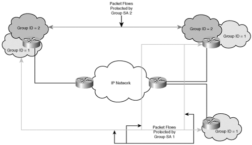
At this point, decryption and decapsulation occurs, and the multicast packet continues on the MDT in the clear. Figure 8-17 shows the topological association of two GSAs among various group members.
The multicast security model enables a much more efficient method for distributing encrypted multicast traffic by leveraging the multicast replication of the core IP network. The encrypting gateway is responsible for encrypting the multicast traffic and forwarding it to the core; it is no longer responsible for replication of the multicast packet to every receiving VPN gateway. The group security association allows any valid member of the group to encrypt or decrypt traffic such that the number of security associations is minimized on the VPN gateways. Keep in mind that the group security association doesn’t mitigate the need for IPSec SAs to accommodate unicast traffic flows. The primary motivation for using multicast security is to provide an efficient means of encrypting and replicating encrypted multicast traffic.
Our analysis of multicast encryption has shown that the overlay tunnel topologies have a significant impact on the creation of the multicast distribution trees. The peer-to-peer nature of IPSec fundamentally conflicts with the communication paradigm induced by multicast. The IETF’s effort to improve the relationship between multicast and encryption methods has led to the establishment of a group security model that is fundamentally different from the peer-to-peer model used by IPSec. Research on how to improve the relationship between unicast and multicast security continues using a common security infrastructure.
In this chapter, you have seen it demonstrated that the IPSec peer-to-peer model has a significant impact on the support of enhanced applications such as VoIP and multicast. Also highlighted was the impact that encryption has on the QoS models used to prioritize these enhanced applications. Specifically, the use of the IP DSCP or precedence values was emphasized as the common denominator for queuing before encryption, between encryption peers, and after encryption. It is critical to use a consistent QoS classification model in the convergence of voice and data streams on a common IPSec topology. Fortunately, the IPSec peer model readily accommodates the point-to-point nature of VoIP communications. In contrast, the multicast communication paradigm does not conform to the IPSec peer model. Network architects must analyze the organization’s application communication requirements and business requirements to select the appropriate IPSec paradigm and topology. In doing so, a number of trade-offs are made with regard to optimal topology, traffic management, capacity planning, and provisioning complexity. Many enterprises are turning to service provider solutions such as MPLS/VPN services in order to optimize their application deployment models, capacity planning, and traffic engineering. The final chapter steps through the relationship of IPSec VPN solutions in conjunction with other network-based VPN solutions such as MPLS VPNs.