
In Chapter 2, “IPSec Overview,” and Chapter 3, “Enhanced IPSec Features,” you reviewed the fundamental concepts of IPSec VPNs. In this chapter, you will use those concepts to learn about IPSec VPN architectures. As you read in Chapter 1, “Introduction to VPNs,” VPNs have been around for many years. Conceptually, the process of designing an IPSec VPN network is no different from the one used to determine any other VPN architecture, such as Frame Relay; however, IPSec adds a few more constraints and capabilities. In this chapter, you will be presented with the aspects that differentiate IPSec VPN networks from traditional VPN architectures, and understand key considerations when designing such a network.
Before getting into IPSec VPN architectures, you’ll review several IPSec connection models. These connection models are the mechanisms that are used to provide protected communication between VPN endpoints. You might think of them as the basic building blocks of an IPSec VPN architecture. We will explore three connectivity models:
IPSec model
GRE model
Remote access client model
Each of these connection models has unique capabilities and constraints, which you will need to consider carefully when deciding which model will be most effective in the VPN architecture. Each of the models requires the presence of IP connectivity between the IPSec endpoints. The knowledgeable network designer will recognize that a scalable and reliable IPSec VPN architecture may leverage more than one connection model. The intent of this chapter is to guide the network designer in the choice of the connection model in order to achieve the optimal VPN architecture.
As you learned in Chapter 2, “IPSec Overview,” the simplest connectivity model is achieved by creating an IPSec VPN between two sites, which is commonly referred to as site-to-site connectivity using the IPSec model. The sites can be connected over private IP networks such as Frame Relay or ATM networks running IP using transport mode or over the public Internet using tunnel mode.
Note
IPSec encryption is applied after a clear text packet is received, a routing decision is made, and an interface is selected for egress transmission. The IPSec policy is applied to the egress interface where the encryption process is one of the last functions called upon prior to transmission of the packet. Similarly, encrypted packets received over an interface where an IPSec policy is applied are decrypted prior to the completion of the routing decision and forwarding action. Here, the focus is on the IPSec policy associated with the egress interface for encrypting packets and the ingress interface for decrypting packets. Usually, the egress and ingress interface is one and the same; therefore, the IPSec policy is consistent for both forward and reverse packet flows.
If the IPSec gateways have multiple egress interfaces, routing policy on the endpoints should ensure that the interface used for egress and ingress traffic is the same as the interface where the IPSec policy is applied. The issue of link redundancy and fault tolerance is discussed in detail in Chapter 6, “Designing Fault-Tolerant IPSec VPNs.”
The IPSec model is conceptually simple to understand—it protects unicast traffic from one subnet to another. The IPSec model is generally the lowest common denominator from the perspective of capability of the IPSec nodes and their ability to establish connectivity between sites. Although the protection model is conceptually simple, the configuration of the model can get quite complex for large VPNs. Operators must explicitly configure a protect profile for traffic between every potential subnet. The addition of a single subnet in the VPN may require configuration updates to all the other VPN gateways in the network. Network designers must carefully allocate IP address blocks at each site in order to minimize the amount of explicit configuration of discrete IPSec proxy profiles. In some cases, network planners may have little control over the address allocation methods, which could result in a network with inefficient subnet addressing. A poorly architected network using the basic IPSec model will quickly become unmanageable. Clearly, there is a motivation to decouple the subnet address allocation from the IPSec policy definitions in order to simplify provisioning.
Another disadvantage of the IPSec model is the lack of support for IP multicast, as the original IPSec RFCs did not accommodate multicast in the IPSec proxy statements. Many IGP dynamic routing protocols (such as OSPF, EIGRP, and RIP) use IP multicast to establish routing adjacencies. Most enterprises rely on Interior Gateway Protocols (IGP) to dynamically discover the optimal paths through the VPN. The IPSec model mitigates the value of the IGP, essentially making the IPSec proxy statements behave as static routes.
Note
BGP may be used in lieu of an IGP because it uses TCP unicast packets to build adjacencies between peers. However, the use of BGP does not mitigate the requirement to explicitly define the IPSec proxy profiles for traffic flowing between all the distinct subnets.
It is evident that the requirement to explicitly define every potential IP flow on every VPN gateway is not a viable method for a large, complex network with hundreds, or even thousands, of subnets. In the next section, you’ll explore how routing protocols can be exchanged over IPSec-enabled virtual interfaces in order to simplify the IPSec policies.
In Chapter 2, “IPSec Overview,” you saw that there are certain limitations for support of dynamic routing and IP multicast when using the IPSec model for site-to-site connectivity. One way to overcome these limitations is to use generic route encapsulation (GRE) tunneling of site-to-site traffic protected by IPSec. The notable advantage of this GRE model is that it simplifies configuration for site-to-site VPN connectivity. In the GRE model, all traffic between sites traverses a GRE tunnel that is protected by IPSec; therefore, IPSec profiles in this model are applied to packets that originate and terminate at the GRE tunnel interface. A VPN built with GRE and IPSec protection can be broken into four basic functions:
Creating the GRE tunnel
Protecting the GRE tunnel with IPSec
Providing IP connectivity between the GRE tunnel and IPSec endpoints (routing outside the VPN)
Providing a viable routing path for endsystems through the GRE tunnels (routing within the VPN)
The combination of GRE tunnel and IPSec protection decouples the dynamic routing requirements and subnet-to-subnet traffic flow from the IPSec protection policy. IPSec protection is dramatically simplified by virtue of the fact that a single IPSec proxy profile may be defined for the GRE tunnel that carries all traffic flowing between two VPN gateways regardless of the type, source, or destination. The compromise with using the GRE model, however, is that two routing planes are required:
A routing plane between the VPN gateways routes encrypted tunnel packets
A routing plane between the VPN gateways through the tunnel provides routing paths between the end-user subnets
Therefore, the GRE model minimizes the IPSec provisioning requirements while creating a tunnel overlay network that complicates management and introduces an entirely different set of scalability constraints.
The requirement of encrypting traffic between software clients (for example, PCs, PDAs, kiosks, and the like) and VPN gateways presents a whole different set of challenges. The remote access client model requires a very different set of capabilities to accommodate dynamic host address assignment, lack of configuration control, and temporal connections. Both the IPSec model and the GRE model work well for site-to-site connectivity wherein all the IP addresses of all the IPSec endpoints are known in advance and pre-configured in the sites of the VPN gateway. However, these two models will not work for a telecommuter trying to connect to a corporate VPN, as the corporate site accepting the telecommuter’s IPSec connection does not know the IP address in advance. You’ll need an efficient and scalable manner to allow remote access clients to access the corporate VPN. In Chapter 3, “Enhanced IPSec Features,” you saw how a remote access client initiates a connection to its IPSec endpoint, which is typically a hub. Using the advanced IPSec features, the remote access client model allows the client to use a dynamically assigned IP address. It also allows the network provisioning staff to define a policy that is pushed to the client to simplify network operations management. Neither the IPSec nor the GRE model provides this capability. You need a new method to exchange these capabilities and attributes during the establishment of the IPSec connection. You can accomplish the capability and attribute exchange using extensions to IKE. The IKE Mode Config process assigns connection attributes to the client, assuming that it is a single host. The typical attributes assigned include the following:
Private IP address
Private DNS server
Private WINS server
Private domain name
The private IP address is usually assigned from an address pool configured on the hub. Then, an IPSec proxy is created to protect traffic from the assigned private address to a range of addresses protected by the hub. The hub advertises the address pool to other network devices such that a return path is provided to the client. The client typically directs all user traffic to the hub when split tunneling is not allowed.
The remote access client model obviously simplifies the provisioning process by automating the policy distribution to the clients using IKE Mode Config. The protection policies may be centrally defined and managed such that the network operator is not required to configure each remote endpoint. There are a couple of disadvantages with this model. First, the IPSec connections can only be initiated from the client to the server. Second, the connection uses a simple IPSec proxy statement that doesn’t support multicast.
Three IPSec connection models have been presented, each with their own pros and cons. As a network designer, you must assess the scalability requirements, stability requirements, and application requirements in order to select the appropriate connection model. Often, a combination of the connection models is required in order to scale IPSec connectivity over a large enterprise network. Now that you’ve seen the basic capabilities of the various connection models, you’ll see how these tools apply to the various network architectures.
In the remaining sections of this chapter, you will be presented with the variety of IPSec VPN architectures that are possible using the connection models previously discussed, and will delve into the pros and cons of each model. Figure 5-1 is provided as a reference network on which the various architecture models are applied. In many cases, a subset of routers from the reference network is used to provide clarity. Most of the possible architectures are a subset of the following two most common architectural models:
Hub-and-spoke topology
Full-mesh topology

The network designer’s selection of topology is driven primarily by the application needs of the VPN. Other important factors are simplicity, scalability, efficiency, and—of course—cost.
One of the most common IPSec architectural models is the hub-and-spoke model shown in Figure 5-2.
In this model, all the spokes are connected to the hub via IPSec tunnels; there is no direct communication between the spokes and all traffic between spokes must first pass through the hub. This model is cost-effective when the application needs of a VPN don’t require significant spoke-to-spoke connectivity. This model is also simple to provision and operate because the number of point-to-point IPSec relationships scales linearly with the number of spokes. In this model, the heart and soul is obviously the hub, and thus any downtime on the hub will have a severe impact on the VPN connectivity. Fault-tolerant designs for hub failures are addressed in Chapter 6, “Designing Fault-Tolerant IPSec VPNs.”
One of the most critical aspects of the IP network design process is the proper allocation of IP address subnets; this is also true for IPSec VPNs. Traditional Frame Relay or Asynchronous Transfer Mode (FR/ATM) hub-and-spoke networks place all the Layer 3 routing complexity at the hub, where hundreds—if not thousands—of remote sites connect. The network architect will typically assign the IP address ranges at each site such that the address space is assigned efficiently while simplifying the routing processes. The typical hub-and-spoke architecture requires an explicit route at the hub site for each remote spoke’s address range. Likewise, each spoke will require a route to the IP address range assigned to the hub site. A reciprocal pair of static routes is all that is required on the connection between the hub and spoke. Dynamic routing may be used between the hub and its spokes to simplify the routing configuration, particularly at the hub site.
Note
Dynamically exchanging protected routes between IPSec sites generally requires GRE (or IP) encapsulation of the routing protocols. IPSec may then protect the IP-encapsulated routing exchanges.
It is easy to see how the scalability of the IPSec VPN comes into question at the hub side. Each site requires a minimum of two IPSec security associations (one for traffic in each direction) and an IKE security association. If the IP address ranges at either end of the site-to-site connection cannot be represented as a single IP address block because non-contiguous IP address ranges are used at the hub or spokes, then additional IPSec SAs may be required between each hub and spoke connection. Therefore, the proper allocation of IP address ranges is of paramount importance for scalability and reducing configuration complexity. Figure 5-3 shows the addressing used in the previous example of an IPSec VPN in a hub-and-spoke topology.
Example 5-1 shows the IPSec configuration for the hub site shown in Figure 5-3. Note that a single crypto map is used on the interface with multiple sequence numbers in the crypto map. Each sequence number represents a unique spoke. Associated with each sequence number is the access list that matches transit packets on the interface to the appropriate spoke. The access list associated with each spoke essentially “routes” the packets to that peer. Note also that the only routing statement is the default route to the backbone network.
Example 5-1. Native IPSec Hub Configuration
hostname vpn-gw1-west
!
crypto isakmp policy 10
 hash md5
 authentication pre-share
 lifetime 3600
crypto isakmp key cisco address 9.1.1.130
crypto isakmp key cisco address 9.1.1.134
crypto isakmp key cisco address 9.1.1.138
crypto isakmp key cisco address 9.1.1.142
crypto isakmp key cisco address 9.1.1.146
crypto isakmp key cisco address 9.1.1.150
crypto isakmp keepalive 10 10
!
crypto ipsec transform-set esp-tunnel-internet esp-3des esp-md5-hmac
!
! Unique crypto map sequence associated with each spoke
crypto map vpn 10 ipsec-isakmp
 set peer 9.1.1.130
 set transform-set esp-tunnel-internet
 match address esp-spoke-1-west
!
crypto map vpn 20 ipsec-isakmp
 set peer 9.1.1.134
 set transform-set esp-tunnel-internet
 match address esp-spoke-2-west
!
crypto map vpn 30 ipsec-isakmp
 set peer 9.1.1.138
 set transform-set esp-tunnel-internet
 match address esp-spoke-1-central
!
crypto map vpn 40 ipsec-isakmp
 set peer 9.1.1.142
 set transform-set esp-tunnel-internet
 match address esp-spoke-2-central
!
crypto map vpn 50 ipsec-isakmp
 set peer 9.1.1.146
 set transform-set esp-tunnel-internet
 match address esp-spoke-1-east
!
crypto map vpn 60 ipsec-isakmp
 set peer 9.1.1.150
 set transform-set esp-tunnel-internet
 match address esp-spoke-2-east
!
interface Serial1/0:0
 ip address 9.1.1.22 255.255.255.252
 crypto map vpn
!
interface Ethernet4/0
 ip address 10.1.0.1 255.255.255.0
 duplex half
!
! Default route to the backbone
ip route 0.0.0.0 0.0.0.0 9.1.1.21
!
! Access list associated with each spoke
ip access-list extended esp-spoke-1-west
 permit ip 10.1.0.0 0.0.0.255 10.0.64.0 0.0.0.255
ip access-list extended esp-spoke-2-west
 permit ip 10.1.0.0 0.0.0.255 10.0.65.0 0.0.0.255
ip access-list extended esp-spoke-1-central
 permit ip 10.1.0.0 0.0.0.255 10.0.66.0 0.0.0.255
ip access-list extended esp-spoke-2- central
 permit ip 10.1.0.0 0.0.0.255 10.0.67.0 0.0.0.255
ip access-list extended esp-spoke-1-east
 permit ip 10.1.0.0 0.0.0.255 10.0.68.0 0.0.0.255
ip access-list extended esp-spoke-2- east
 permit ip 10.1.0.0 0.0.0.255 10.0.69.0 0.0.0.255
!
Example 5-2 shows the output listing resulting from the configuration on the hub. A single crypto map is presented for clarity; however, there will be a unique crypto map instance for each spoke. Note also that the route listing does not specify a route to the spoke’s protected address; only the default route is needed to force the traffic through the interface where the IPSec access list takes affect. Emphasis should be placed on the source address range that the hub is protecting. Note that the range includes only the LAN connected to the hub site.
Example 5-2. Native IPSec Hub Configuration State
vpn-gw1-west#show crypto map
Crypto Map "vpn" 10 ipsec-isakmp
        Peer = 9.1.1.130
	Extended IP access list esp-spoke-1-west
	 access-list esp-spoke-1-west permit ip 10.1.0.0 0.0.0.255 10.0.64.0 0.0.0.255
	Current peer: 9.1.1.130
	Security association lifetime: 4608000 kilobytes/3600 seconds
	PFS (Y/N): N
	Transform sets={ esp-tunnel-internet, }
                Serial1/0:0
...

vpn-gw1-west#show ip route
Gateway of last resort is 9.1.1.21 to network 0.0.0.0

     9.0.0.0/8 is variably subnetted, 1 subnets
C       9.1.1.20/30 is directly connected, Serial1/0:0
     10.0.0.0/8 is variably subnetted, 1 subnets
C       10.1.0.0/24 is directly connected, Ethernet4/0
S*   0.0.0.0/0 [20/0] via 9.1.1.21, 3d15h
Example 5-3 provides the configuration listing for the spoke site with a reciprocal IPSec proxy statement. The spoke may also use a default route to the backbone network with a single crypto map to direct traffic to the hub site. The other spokes would use a similar configuration with the IPSec proxy modified for the address space protected by the spoke.
Example 5-3. Native IPSec Spoke Configuration
spoke-1-west #show running-config
!
hostname spoke-1-west
!
crypto isakmp policy 10
 hash md5
 authentication pre-share
 lifetime 3600
crypto isakmp key cisco address 9.1.1.22
crypto isakmp keepalive 10
!
!
crypto ipsec transform-set esp-tunnel-internet esp-des esp-md5-hmac
!
! Crypto map for hub site peer
crypto map vpn 10 ipsec-isakmp
 set peer 9.1.1.22
 set transform-set esp-tunnel-internet
 match address esp-tunnel-list
!
!
interface Ethernet0
 ip address 10.0.64.1 255.255.255.0
!
interface Serial0
 ip address 9.1.1.130 255.255.255.252
 crypto map vpn
!
! default route to the backbone
ip route 0.0.0.0 0.0.0.0 9.1.1.129
!
! Protected address ranges from spoke to hub
ip access-list extended esp-tunnel-list
 permit ip 10.0.64.0 0.0.0.255 10.1.0.0 0.0.0.255
end
Example 5-4 provides the configuration state on SPOKE-1-WEST. Particular attention should be given to the address ranges that the spoke protects traffic from and to. This attribute will be exploited as additional functionality is provided. The current configuration protects traffic only destined to the IP address range assigned to the hub site, as opposed to traffic to any other spoke. Refer to Figure 5-3.
Example 5-4. Native IPSec Spoke Configuration State
spoke-1-west#show crypto map
Crypto Map "vpn" 10 ipsec-isakmp
        Peer = 9.1.1.22
        Extended IP access list esp-tunnel-list
          access-list esp-tunnel-list permit ip 10.0.64.0 0.0.0.255 10.1.0.0 0.0.0.255
        Current peer: 9.1.1.22
        Security association lifetime: 4608000 kilobytes/3600 seconds
        PFS (Y/N): N
        Transform sets={ esp-tunnel-internet, }
                Serial0
spoke-1-west#show ip route
Gateway of last resort is 9.1.1.129 to network 0.0.0.0

     9.0.0.0/30 is subnetted, 1 subnets
C       9.1.1.128 is directly connected, Serial0
     10.0.0.0/8 is variably subnetted, 1 subnets
C       10.0.64.0/24 is directly connected, Ethernet0
S*   0.0.0.0/0 [1/0] via 9.1.1.129
One possible way to reduce the configuration complexity at the hub is to define a crypto profile at the hub that matches any remote site’s address range. This approach works only when the spokes initiate the traffic to the hub. The hub cannot initiate a connection to the spokes because the crypto profile does not uniquely identify an appropriate spoke. When the spokes initiate connections to the hub, the inverse of the spoke’s IPSec proxy statement will be installed on the hub; it must be a subset of the hub’s crypto profile allowing return traffic to be directed to the appropriate spoke. For example, if SPOKE-1-WEST is initiating a connection to VPN-GW1-WEST with protection (FROM: 10.0.64.0/24, TO: 10.1.0.0/24), the inverse of this protection profile is (FROM: 10.1.0.0/24, TO: 10.0.64.0/24). The hub’s profile must at least protect (FROM: 10.1.0.0/24, TO: 10.0.64.0/24). In order to support other spokes, the hub’s protection profile might be increased to “cover” the addresses (FROM: 10.1.0.0/24, TO: 10.0.0.0/8). The hub’s generic profile doesn’t provide enough information for it to initiate IPSec connections for outbound traffic to the appropriate spokes; however, the hub can accept IPSec connections from any of the spokes that are protecting more specific subnets than 10.0.0.0/8. Assuming each spoke protects a unique address range and initiates the connection to the hub, the hub will have sufficient information to direct packets to the appropriate spoke if the packets are routed out this protected subnet.
Note
Mismatched crypto profiles commonly cause IKE phase 2 processing errors, so this model is not recommended. A more appropriate solution to reduce complexity at the hub might be to implement a dynamic crypto map on the hub.
In summary, the hub-and-spoke architecture using the native IPSec model provides encrypted simple IP connectivity between the hub-and-spoke sites. Contiguous address assignment of IP address ranges is critical for reducing the complexity of the VPN connectivity. The next section addresses transit routing at the hub site, which highlights the importance of address assignment.
The simple hub-and-spoke connectivity model described in the previous section provides remote site connectivity services only to the hub site. There is no connectivity enabled between the spokes in this model. Generally, this connectivity is sufficient for many applications such as customer–supplier extranets in which the suppliers have no need to communicate among themselves. But, this model doesn’t meet the needs of enterprise VPNs where spoke-to-spoke connectivity is occasionally required.
This requirement adds an additional provisioning complexity on the IPSec VPN. One option is to build direct IPSec peer relationships between the spokes, effectively turning every spoke into a hub. The subsequent section explores this complex scenario using full-mesh VPNs. For this example, assume that the VPN topology will remain as hub-and-spoke.
To achieve spoke-to-spoke connectivity through the hub without building IPSec peer relationships directly between the spokes, the hub site VPN device must provide routing and IPSec protection for transit traffic. You have seen previously that the routing process in a private network provides sufficient information to the hub and spokes such that traffic is directed out the appropriate IPSec-protected interfaces. The same is true for Internet-connected devices for which default routes are common. However, the IPSec protection profiles must be modified to accommodate the new transit spoke-to-spoke traffic flows at the hub. The following sequence of events occurs for transit traffic flows as depicted in Figure 5-4:
Packets leaving SPOKE-1-WEST for a host protected by SPOKE-2-WEST will be encrypted by SPOKE-1-WEST with the security association for the VPN-GW1-WEST.
The hub VPN-GW1-WEST decrypts the packets arriving from SPOKE-1-WEST.
The hub VPN-GW1-WEST routing table decides that the packet is destined to another spoke that is accessible through the same IPSec-protected interface upon which the packet was received.
The hub VPN-GW1-WEST encrypts the packet again, which is destined for the remote spoke using the security association with the destination SPOKE-2-WEST.
SPOKE-2-WEST decrypts the packet from the hub VPN-GW1-WEST.
The remote SPOKE-2-WEST forwards the packet to the destination host.
In our previous hub-and-spoke example where no spoke-to-spoke connectivity was required, the hub site crypto profile was applied to traffic that originated or terminated at the hub site. For spoke-to-spoke connectivity via the hub, the profiles must be modified to protect every potential spoke-to-spoke source and destination pair. Although the simplest way to achieve this would appear to be by creating a crypto profile that matches any-to-any source-destination pair, unfortunately, this will not work. Recall that the IPSec profiles direct packets to remote crypto gateways following the routing function at the hub site. The key difference is that routing is only directing packets based on the destination address, whereas IPSec directs packets based on the 5-tuple—source address, destination address, IP protocol field, source port, and destination port. The IPSec profiles must associate the subnets assigned to a remote site with that site’s IPSec peer endpoint. Likewise, the hub must match the security association with an inverse profile, which the spoke uses to protect its subnet. Figure 5-4 shows the transit routing requirements at the hub site. Note that this method is demonstrated using simple route aggregates in which there is an order of N provisioned crypto proxy statements, O(N), where N represents the number of spokes. With inefficient address assignments, the provisioning may become as complex as configuring O(N^2) proxy profiles. Clearly, you should, at all costs, avoid addressing schemes that don’t leverage route aggregation.
The topology provides some insight into how the crypto map profiles must be designed. The use of contiguous IP address ranges allows the aggregation of spoke routes using a single CIDR block of 10.0.0.0/16. Table 5-1 shows the discrete crypto proxy matrix required for any-to-any connectivity over the hub-and-spoke topology. Table 5-2 shows the aggregate crypto map profiles required.
Table 5-1. IPSec Proxy Matrix for Transit Hub-and-Spoke Topology
Hub Matrix | ||||
|---|---|---|---|---|
To | VPN-GW1-WEST 10.1.0.0/24 | SPOKE-1-WEST 10.0.64.0/24 | SPOKE-2-WEST 10.0.65.0/24 | SPOKE-1-EAST 10.0.68.0/24 |
From | ||||
VPN-GW1-WEST 10.1.0.0/ 24 | X | 10.1.0.0/24 to 10.0.64.0/24 | 10.1.0.0/24 to 10.0.65.0/24 | 10.0.64.0/24 to 10.0.68.0/24 |
SPOKE-1-WEST 10.0.64.0/24 | 10.0.64.0/24 to 10.1.0.0/24 | X | 10.0.64.0/24 to 10.0.65.0/24 | 10.1.0.0/24 to 10.0.68.0/24 |
SPOKE-2-WEST 10.0.65.0/24 | 10.0.65.0/24 to 10.1.0.0/24 | 10.0.65.0/24 to 10.0.64.0/24 | X | 10.0.65.0/24 to 10.0.68.0/24 |
SPOKE-1-EAST 10.0.68.0/24 | 10.0.68.0/24 to 10.1.0.0/24 | 10.0.68.0/24 to 10.0.64.0/24 | 10.0.68.0/24 to 10.0.65.0/24 | X |
Table 5-2. Crypto Map Profiles for Transit Hub Traffic
Crypto Map Applied | Remote Site | Source |
|---|---|---|
VPN-GW1-WEST | SPOKE-1-WEST | 10.0.0.0/8 -> 10.0.64.0/24 |
VPN-GW1-WEST | SPOKE-2-WEST | 10.0.0.0/8 -> 10.0.65.0/24 |
VPN-GW1-WEST | SPOKE-1-EAST | 10.0.0.0/8 -> 10.0.68.0/24 |
SPOKE-1-WEST | VPN-GW1-WEST | 10.0.64.0/24 -> 10.0.0.0/8 |
SPOKE-2-WEST | VPN-GW1-WEST | 10.0.65.0/24 -> 10.0.0.0/8 |
SPOKE-1-EAST | VPN-GW1-WEST | 10.0.68.0/24 -> 10.0.0.0/8 |
As seen in the tables, the aggregate crypto map (that is, 10.0.0.0/8) dramatically simplifies configuration complexity, especially in a large network. The introduction of addresses outside the aggregate address range of 10.0.0.0/0 will increase the configuration complexity. For example, the introduction of an address range of 192.168.0.0/24 on one of the spokes will double the configuration complexity. Also notice that the hub’s outbound crypto map profile includes the reciprocal profile for traffic arriving from that spoke. Therefore, the hub knows which peer to use for encrypting traffic for each subnet and also knows which profile to associate for decrypting traffic arriving from each spoke. It is apparent that a properly assigned address space can dramatically simplify the configuration at the hub. The configuration samples that follow demonstrate how the crypto map profiles satisfy the any-to-any communication requirements through the hub-and-spoke topology.
The hub configuration for transit VPN traffic is modified such that traffic received from any spoke may be redirected out the same interface (by hair-pinning traffic—that is, by decrypting and re-encrypting a flow) to the appropriate spoke peer. The configuration listing in Example 5-5 is truncated to focus attention on the relevant changes from the previous configuration listing where spoke-to-spoke communication was not allowed. The only change made in the configuration in Example 5-5 is the masked address range for traffic from the hub site. This masked range highlights the importance of a VPN with proper IP address assignment. If any of the spokes protect an IP address range that is non-contiguous with 10.0.0.0/8, then a unique set of IPSec proxies must be defined for each non-contiguous IP address range.
Example 5-5. IPSec Hub Configuration for Transit VPN Traffic
hostname vpn-gw1-west
!
crypto map vpn 10 ipsec-isakmp
 set peer 9.1.1.130
 set transform-set esp-tunnel-internet
 match address esp-spoke-1-west
!
crypto map vpn 20 ipsec-isakmp
 set peer 9.1.1.134
 set transform-set esp-tunnel-internet
 match address esp-spoke-2-west
!
...
!
ip access-list extended esp-spoke-1-west
 permit ip 10.0.0.0 0.255.255.255 10.0.64.0 0.0.0.255
ip access-list extended esp-spoke-2-west
 permit ip 10.0.0.0 0.255.255.255 10.0.65.0 0.0.0.255
ip access-list extended esp-spoke-1-central
 permit ip 10.0.0.0 0.255.255.255 10.0.66.0 0.0.0.255
ip access-list extended esp-spoke-2-central
 permit ip 10.0.0.0 0.255.255.255 10.0.67.0 0.0.0.255
ip access-list extended esp-spoke-1-east
 permit ip 10.0.0.0 0.255.255.255 10.0.68.0 0.0.0.255
ip access-list extended esp-spoke-2-east
 permit ip 10.0.0.0 0.255.255.255 10.0.69.0 0.0.0.255
!
Example 5-6 shows the configuration state of the hub site with a source address range in the IPSec proxy that includes traffic from any other spoke. In addition, the IPSec proxy specifies the traffic to be directed to the appropriate spoke even though the hub router only uses a default route to the backbone network.
Example 5-6. Native IPSec Hub Configuration State for Transit VPN Traffic
vpn-gw1-west#show crypto map
Crypto Map "vpn" 10 ipsec-isakmp
        Peer = 9.1.1.130
        Extended IP access list esp-spoke-1-west
            access-list esp-spoke-1-west permit ip 10.0.0.0 0.255.255.255 10.0.64.0
0.0.0.255
        Current peer: 9.1.1.130
        Security association lifetime: 4608000 kilobytes/3600 seconds
        PFS (Y/N): N
        Transform sets={ esp-tunnel-internet, }
                Serial1/0:0
...
vpn-gw1-west#show ip route
Gateway of last resort is 9.1.1.21 to network 0.0.0.0

     9.0.0.0/8 is variably subnetted, 1 subnets
C       9.1.1.20/30 is directly connected, Serial1/0:0
     10.0.0.0/8 is variably subnetted, 1 subnets
C       10.1.0.0/24 is directly connected, Ethernet4/0
S*   0.0.0.0/0 [20/0] via 9.1.1.21, 3d15h
Examples 5-7 and 5-8 show the modified IPSec proxy profile for a selected spoke and the resulting configuration state. The configuration allows the spoke to encrypt and direct traffic to the hub site for traffic destined to any other spoke.
Example 5-7. Native IPSec Spoke Configuration for Transit VPN Traffic
spoke-1-west #show runring-config
!
hostname spoke-1-west
!
crypto map vpn 10 ipsec-isakmp
 set peer 9.1.1.22
 set transform-set esp-tunnel-internet
 match address esp-tunnel-list
!
...
!
ip access-list extended esp-tunnel-list
 permit ip 10.0.64.0 0.0.0.255 10.0.0.0 0.255.255.255
end
Example 5-8. IPSec Spoke Configuration State for Transit VPN Traffic
vpn-gw1-west#show crypto map
Crypto Map "vpn" 10 ipsec-isakmp
        Peer = 9.1.1.22
        Extended IP access list esp-tunnel-list
            access-list esp-tunnel-list permit ip 10.0.64.0 0.0.0.255 10.0.0.0
0.255.255.255
        Current peer: 9.1.1.22
        Security association lifetime: 4608000 kilobytes/3600 seconds
        PFS (Y/N): N
        Transform sets={ esp-tunnel-internet, }
                Serial0
spoke-1-west#show ip route
Gateway of last resort is 9.1.1.129 to network 0.0.0.0

     9.0.0.0/30 is subnetted, 1 subnets
C       9.1.1.128 is directly connected, Serial0
     10.0.0.0/8 is variably subnetted, 1 subnets
C       10.0.64.0/24 is directly connected, Ethernet0
S*   0.0.0.0/0 [1/0] via 9.1.1.129
Note
The Cisco IOS product line allows hair-pinning of traffic on the same interfaces. Because the Cisco PIX product line is currently not capable of hair-pinning IPSec traffic on a single interface, a second IPSec-enabled interface is required to hairpin traffic in the PIX.
The proper allocation of addresses within the VPN certainly simplifies configuration complexity. Thus far, we have only considered traffic that stays within the VPN. One of the motivations for building IPSec VPNs over the Internet is to provide both VPN and Internet services over a common infrastructure in order to achieve cost optimization. Next, you’ll explore how Internet access is coupled with hub-and-spoke topology.
Internet access is a typical requirement for most sites within a VPN. In a hub-and-spoke scenario it is possible for the remote spoke sites to have Internet access using split tunneling. Split tunneling is a method of forcing IPSec protection for certain traffic flows leaving an interface while excluding other traffic flows from IPSec protection (for example, Internet traffic). Many enterprises will not accept this model due to increased exposure to security vulnerabilities.
The most manageable and secure option for offering Internet access to VPN sites is the centralized firewall option in which all traffic to the Internet passes through a firewall at the hub. You saw earlier that the any-to-any provisioning model at the hub provided insufficient information in order to associate traffic to the appropriate spoke. You also have seen that aggregate profiles simplify configuration complexity. In a properly designed network, the largest aggregate route (that is, any source or any destination) may be used to simplify the configuration. In fact, it may be the only way to get traffic to the Internet because the destination addresses on the Internet are not known a priori. If you consider the requirement for each spoke to send traffic for any address to the hub, the inverse property is for the hub to send traffic with any source to the spoke with the associated destination address. You find in this scenario that all of the transit traffic requirements may be represented by a single aggregated IPSec crypto profile. As a result, the crypto map profiles are significantly simplified, as shown in Table 5-3.
Table 5-3. Crypto Map Profiles for Hubs and Spokes
Crypto Map Applied | Remote Site | Source |
|---|---|---|
VPN-GW1-WEST | SPOKE-1-WEST | Any -> 10.0.64.0/24 |
VPN-GW1-WEST | SPOKE-2-WEST | Any -> 10.0.65.0/24 |
VPN-GW1-WEST | SPOKE-1-EAST | Any -> 10.0.68.0/24 |
SPOKE-1-WEST | VPN-GW1-WEST | 10.0.64.0/24 -> Any |
SPOKE-2-WEST | VPN-GW1-WEST | 10.0.65.0/24 -> Any |
SPOKE-1-EAST | VPN-GW1-WEST | 10.0.68.0/24 -> Any |
A simple modification to the IPSec proxy profiles on the hub and spoke is all that is required to facilitate Internet access via the hub site. In this example, none of the spokes is allowed to perform split tunneling. Example 5-9 shows the hub configuration listing and Example 5-10 shows the SPOKE-1-WEST configuration modifications.
Example 5-9. Native IPSec Hub Configuration for Internet Access
ip access-list extended esp-spoke-1-west
 permit ip 0.0.0.0 255.255.255.255 10.0.64.0 0.0.0.255
!
Example 5-10. Native IPSec Spoke Configuration for Internet Access
ip access-list extended esp-tunnel-list
 permit ip 10.0.64.0 0.0.0.255 0.0.0.0 255.255.255.255
!
Clearly, the transit communication model with Internet access simplifies the IPSec profile for both the hub and spoke site. What we have compromised is the granularity of security control mechanisms for protecting specific flows of traffic between the sites. Usually this is not an issue for enterprise traffic.
The IPSec VPN hub-and-spoke model introduces new constraints that the designer may not have encountered with traditional VPNs. The fact that the IPSec profiles effectively act as routing entries may simplify the routing protocols where default routes exist; however, the complexity of the IPSec profiles mitigates the advantage. A large IP VPN with poorly allocated address space may require O(N^2) IPSec configuration profiles at the hub, where N is the number of spokes. The use of aggregate IP address ranges can reduce the number of IPSec configuration entries to O(N) if the designer assigns the appropriate address space to the remote sites. Regardless, the scalability of the hub is critical to the proper functioning of the VPN. The hub must satisfy memory requirements for data structures supporting IKE and IPSec SAs. The hub must also satisfy the additional processing requirements for IKE state management and IPSec data traffic forwarding. The processing constraints will limit the number of spokes supported as well as the volume of transit data. In most cases, hardware-accelerated IPSec data forwarding is required due to the processing requirements associated with encryption.
Note
While dynamic routing updates may be used to provide explicit routing where default routes are inappropriate, the routing updates typically also require protection. The IPSec profiles discussed thus far do not address the protection of routing updates where the source and destinations are associated with the IPSec tunnel endpoints. The addition of IPSec profiles protecting routing updates (for example, BGP peers within the VPN) significantly increases the configuration complexity. Also note that current IPSec standards do not address IPSec protection of multicast and broadcast packets typically used with dynamic routing protocols such as OSPF, RIP, and EIGRP.
Aside from IPSec scalability, many other scalability constraints need to be addressed to accommodate the building of large-scale VPN networks. We have emphasized IPSec scalability simply because it is likely to be one of the constraints that the operator will encounter early on. You will find that solving the IPSec scalability constraint will likely reveal another scalability constraint such as queuing, routing, or packet-forwarding constraints. Next, you will look at another IPSec model that presents a completely different scalability model.
The hub-and-spoke architecture built with IPSec-protected GRE tunnels significantly simplifies the VPN design process. The primary difference between the GRE model and the IPSec model is the range of addresses protected by the IPSec crypto profile. In the GRE model, the hub crypto map defines a protection profile for encapsulated data originating from the hub’s tunnel source and destined to each spoke’s tunnel interface. The primary advantage is that IPSec profiles do not have to reference addresses assigned in the private LAN. All of the private user traffic is encapsulated inside the tunnel that is represented by a single source and a destination address. Likewise, the spoke requires a crypto map that protects the tunnel source and destination address. The simplification of the IPSec profiles may conserve IPSec memory resources if the tunnel hides the non-contiguous private address ranges that do not follow efficient IP address allocation schemes. Figure 5-5 provides the topology for the GRE hub-and-spoke model.
The hub configuration for the hub-and-spoke topology is provided in Example 5-11. Particular emphasis is placed on the modifications to the IPSec proxy profiles. The IPSec access list specifies the protection of traffic from the hub’s GRE tunnel IP address (9.1.1.22) to each spoke’s GRE tunnel IP address (9.1.1.130, 9.1.1.134, 9.1.1.138, and so on). The protected LAN IP addresses associated with the spokes are explicitly routed into the GRE tunnels. The router encapsulates the packet using the specified GRE tunnel parameters. The GRE-encapsulated packets are subsequently encrypted by IPSec and routed out the serial interface to the backbone. Typically, we will use transport mode on the IPSec tunnel protection profile such that the GRE-encapsulated IP addresses are visible after encryption.
Example 5-11. IPSec-protected GRE Hub Configuration Listing
vpn-gw1-west# show running-config
!
! Transform with transport mode using GRE encapsulation instead of IPsec
crypto ipsec transform-set esp-tunnel-internet esp-des esp-md5-hmac
 mode transport
!
! Sequence of crypto maps – one for each spoke
crypto map vpn 10 ipsec-isakmp
 set peer 9.1.1.130
 set transform-set esp-tunnel-internet
 match address gre-spoke-1-west
crypto map vpn 20 ipsec-isakmp
 set peer 9.1.1.134
 set transform-set esp-tunnel-internet
 match address gre-spoke-2-west
crypto map vpn 30 ipsec-isakmp
 set peer 9.1.1.138
 set transform-set esp-tunnel-internet
 match address gre-spoke-1-central
crypto map vpn 40 ipsec-isakmp
 set peer 9.1.1.142
 set transform-set esp-tunnel-internet
 match address gre-spoke-2-central
crypto map vpn 50 ipsec-isakmp
 set peer 9.1.1.146
 set transform-set esp-tunnel-internet
 match address gre-spoke-1-east
crypto map vpn 60 ipsec-isakmp
 set peer 9.1.1.150
 set transform-set esp-tunnel-internet
 match address gre-spoke-2-east
!
! Set of GRE tunnel interfaces – one for each spoke
!
interface Tunnel0
 ip unnumbered Ethernet4/0
 tunnel source 9.1.1.22
 tunnel destination 9.1.1.130
!
interface Tunnel1
 ip unnumbered Ethernet4/0
 tunnel source 9.1.1.22
 tunnel destination 9.1.1.134
!
interface Tunnel2
 ip unnumbered Ethernet4/0
 tunnel source 9.1.1.22
 tunnel destination 9.1.1.138
!
interface Tunnel3
 ip unnumbered Ethernet4/0
 tunnel source 9.1.1.22
 tunnel destination 9.1.1.142
!
interface Tunnel4
 ip unnumbered Ethernet4/0
 tunnel source 9.1.1.22
 tunnel destination 9.1.1.146
!
interface Tunnel5
 ip unnumbered Ethernet4/0
 tunnel source 9.1.1.22
 tunnel destination 9.1.1.150
!
interface Serial1/0:0
 ip address 9.1.1.22 255.255.255.252
 crypto map vpn
!
interface Ethernet4/0
 ip address 10.1.0.1 255.255.255.0
!
! Static route into tunnel for each spoke's protected IP address
ip route 10.0.64.0 255.255.255.0 Tunnel0
ip route 10.0.65.0 255.255.255.0 Tunnel1
ip route 10.0.66.0 255.255.255.0 Tunnel2
ip route 10.0.67.0 255.255.255.0 Tunnel3
ip route 10.0.68.0 255.255.255.0 Tunnel4
ip route 10.0.69.0 255.255.255.0 Tunnel5
ip route 0.0.0.0 0.0.0.0 9.1.1.21
!
! IPsec proxy profiles protect GRE encapsulated packets from hub to spoke
ip access-list extended gre-spoke-1-central
 permit gre host 9.1.1.22 host 9.1.1.138
ip access-list extended gre-spoke-1-east
 permit gre host 9.1.1.22 host 9.1.1.146
ip access-list extended gre-spoke-1-west
 permit gre host 9.1.1.22 host 9.1.1.130
ip access-list extended gre-spoke-2-central
 permit gre host 9.1.1.22 host 9.1.1.142
ip access-list extended gre-spoke-2-east
 permit gre host 9.1.1.22 host 9.1.1.150 ip
access-list extended gre-spoke-2-west
 permit gre host 9.1.1.22 host 9.1.1.134
!
Note
Notice the configuration in Example 5-11 uses the traditional configuration model for protecting GRE tunnels with IPsec wherein the crypto map configuration is applied to the physical egress interfaces that the GRE tunnel traverses. A newer configuration model was introduced in Chapter 3, “Enhanced IPSec Features,” that uses the ’tunnel protection’ command syntax. This configuration model can also be applied for all the IPsec over GRE examples in this chapter. This new model requires the crypto map configuration to be applied only to the tunnel interface and not the physical interface. The only caveat of the ’tunnel protection’ configuration model is the lack of support for GRE keepalives. Other than this caveat the newer model is a more efficient configuration method and recommended.
The configuration results in a set of crypto maps that protect traffic only between the GRE tunnel endpoints; however, all of the VPN traffic is routed through the tunnels. Therefore, the VPN traffic is always protected while traffic passing outside of the tunnel remains unprotected. Example 5-12 shows the state of the hub configuration.
Example 5-12. GRE Hub Configuration State
vpn-gw1-west#show crypto map
Crypto Map "vpn" 10 ipsec-isakmp
        Peer = 9.1.1.130
        Extended IP access list gre-spoke-1-west
            access-list gre-spoke-1-west permit gre host 9.1.1.22 host 9.1.1.130
        Current peer: 9.1.1.130
        Security association lifetime: 4608000 kilobytes/3600 seconds
        PFS (Y/N): N
        Transform sets={ esp-tunnel-internet, }

Crypto Map "vpn" 20 ipsec-isakmp
        Peer = 9.1.1.134
        Extended IP access list gre-spoke-2-west
            access-list gre-spoke-2-west permit gre host 9.1.1.22 host 9.1.1.134
        Current peer: 9.1.1.134
        Security association lifetime: 4608000 kilobytes/3600 seconds
        PFS (Y/N): N
        Transform sets={ esp-tunnel-internet, }

Crypto Map "vpn" 30 ipsec-isakmp
        Peer = 9.1.1.138
        Extended IP access list gre-spoke-1-central
            access-list gre-spoke-1-central permit gre host 9.1.1.22 host 9.1.1.138
        Current peer: 9.1.1.138
        Security association lifetime: 4608000 kilobytes/3600 seconds
        PFS (Y/N): N
        Transform sets={ esp-tunnel-internet, }

Crypto Map "vpn" 40 ipsec-isakmp
        Peer = 9.1.1.142
        Extended IP access list gre-spoke-2-central
            access-list gre-spoke-2-central permit gre host 9.1.1.22 host 9.1.1.142
        Current peer: 9.1.1.142
        Security association lifetime: 4608000 kilobytes/3600 seconds
        PFS (Y/N): N
        Transform sets={ esp-tunnel-internet, }

Crypto Map "vpn" 50 ipsec-isakmp
        Peer = 9.1.1.146
        Extended IP access list gre-spoke-1-east
            access-list gre-spoke-1-east permit gre host 9.1.1.22 host 9.1.1.146
        Current peer: 9.1.1.146
        Security association lifetime: 4608000 kilobytes/3600 seconds
        PFS (Y/N): N
        Transform sets={ esp-tunnel-internet, }

Crypto Map "vpn" 60 ipsec-isakmp
        Peer = 9.1.1.150
        Extended IP access list gre-spoke-2-east
            access-list gre-spoke-2-east permit gre host 9.1.1.22 host 9.1.1.150
        Current peer: 9.1.1.150
        Security association lifetime: 4608000 kilobytes/3600 seconds
        PFS (Y/N): N
        Transform sets={ esp-tunnel-internet, }
        Interfaces using crypto map vpn:
                Serial1/0:0

vpn-gw1-west#show ip route

Gateway of last resort is 9.1.1.21 to network 0.0.0.0

     9.0.0.0/8 is variably subnetted, 3 subnets, 2 masks
C       9.1.1.20/30 is directly connected, Serial1/0:0
     10.0.0.0/8 is variably subnetted, 5 subnets, 2 masks
C       10.1.0.0/24 is directly connected, Ethernet4/0
S       10.0.64.0/24 is directly connected, Tunnel0
S       10.0.65.0/24 is directly connected, Tunnel1
S       10.0.66.0/24 is directly connected, Tunnel2
S       10.0.67.0/24 is directly connected, Tunnel3
S       10.0.68.0/24 is directly connected, Tunnel4
S       10.0.69.0/24 is directly connected, Tunnel5
S*   0.0.0.0/0 [20/0] via 9.1.1.21, 1d01h
Note
It is critical to note that traffic that is supposed to be routed through a tunnel that is down will be routed out the public interface unencrypted. A common practice is to insert an aggregate static route to a NULL interface for VPN traffic. This drops VPN traffic for an unreachable spoke as opposed to passing it unencrypted to the backbone.
The crypto profile associated with the interface Serial1/0:0 in Example 5-11 protects only the traffic that matches the GRE tunnel profiles specifically protecting the traffic to the spokes. It is important to note that the route forwarding established in Example 5-12 will route any traffic not matching a route to a spoke to the Serial1/0:0 interface. This traffic will not match the crypto profile; therefore, it will not be encrypted. This may be acceptable if the traffic is intended to reach the Internet via this path. If that is not the case, then you will want to prevent traffic from inadvertently leaving the protected network. We can do this by forcing all the traffic that doesn’t match a spoke to NULL route, thereby dropping the traffic. You can use the following to prevent traffic destined to undefined 10.0.0.0/8 addresses from leaving the VPN:
ip route 10.0.0.0 255.0.0.0 NULL0
The reciprocal configuration required of a spoke is provided in Example 5-13. The crypto transform must match the hub (there is no IPSec encapsulation required because GRE encapsulation is used). An important distinction is that you only need to insert a static route for the GRE tunnel endpoint in order to make the tunnel operational. The static route for the hub’s protected address space is directed into the GRE tunnel.
Example 5-13. GRE Spoke Configuration Listing
spoke-2-west#show runring-config
!
crypto isakmp policy 10
 hash md5
 authentication pre-share
 lifetime 3600
crypto isakmp key cisco address 9.1.1.22
crypto isakmp keepalive 10
!
crypto ipsec transform-set esp-tunnel-internet esp-des esp-md5-hmac
 mode transport
!
crypto map vpn 10 ipsec-isakmp
 set peer 9.1.1.22
 set transform-set esp-tunnel-internet
 match address gre-tunnel-list
!
!
interface Ethernet0
 ip address 10.0.65.1 255.255.255.0
!
interface Tunnel0
 ip unnumbered Loopback1
 tunnel source 9.1.1.134
 tunnel destination 9.1.1.22
!
interface Serial0
 ip address 9.1.1.134 255.255.255.252
 crypto map vpn
!

ip route 9.1.1.20 255.255.255.252 9.1.1.133
ip route 10.1.0.0 255.255.255.0 Tunnel0

ip access-list extended gre-tunnel-list
 permit gre host 9.1.1.134 host 9.1.1.22
Note from the spoke’s configuration state shown in Example 5-14 that only the tunnel will be protected. The only traffic passed to the backbone is the encapsulated traffic that is encrypted. All of the VPN traffic will be forced into the GRE tunnel and unreachable destinations are dropped.
Example 5-14. GRE Spoke Configuration State
spoke-2-west#show crypto map
Crypto Map "vpn" 10 ipsec-isakmp
        Peer = 9.1.1.22
        Extended IP access list gre-tunnel-list
            access-list gre-tunnel-list permit gre host 9.1.1.134 host 9.1.1.22
        Current peer: 9.1.1.22
        Security association lifetime: 4608000 kilobytes/3600 seconds
        PFS (Y/N): N
        Transform sets={ esp-tunnel-internet, }
        Interfaces using crypto map vpn:
                Serial0
spoke-2-west#show ip route

     9.0.0.0/30 is subnetted, 6 subnets
S       9.1.1.20 [1/0] via 9.1.1.133
C       9.1.1.132 is directly connected, Serial0
     10.0.0.0/24 is subnetted, 3 subnets
S       10.1.0.0 is directly connected, Tunnel0
C       10.0.65.0 is directly connected, Ethernet0
Once the tunnels are defined and protected from each spoke to the hub, the routing plane for tunnel connectivity must be established. The tunnel source address may be associated with one of the public interfaces or a publicly addressable loopback interface. If the remote peer’s tunnel destination address is not directly connected, the source VPN device will need a route to the tunnel destination. The routes between tunnel endpoints may be learned via dynamic routing on devices between the tunnel endpoints. Alternatively, the VPN devices may have static routes defined to reach the peer’s tunnel endpoint.
At a minimum, the peer’s encapsulating tunnel address must not be routed into the local tunnel interface. Doing so will create a recursive routing loop that will prevent tunnel establishment. An example of recursive routing is when the destination for a tunnel termination point is routed into the local tunnel interface. Once the tunnel interface is defined and has a viable route to the destination address, the status of the interface will transition to an operational UP state. This is true regardless of the reachability of the peer.
Note
A tunnel may provide an UP status, yet fail to pass traffic to the tunnel peer. This may occur when a locally defined static route provides a viable route out of the VPN device but an end-to-end tunnel path does not exist. A viable tunnel path assumes that each router between the tunnel endpoints has routes to these endpoints. In addition, an IPSec security association must be capable of being established for the tunnel. By using GRE keepalives, you can verify that a viable routing path exists and that the IPSec security association is established properly.
With a viable tunnel path, the VPN routing plane may be established through the tunnel. The simplest case is to use static routes into each tunnel interface. The hub must define a static route into the tunnel for each spoke’s protected address range. If the spoke’s protected address range is not contiguous, multiple static routes may be required. Likewise, each spoke will require a static route to the hub’s protected address space. For complex routing scenarios, we may wish to use a dynamic routing protocol within the VPN in order to avoid installing numerous static routes. This is easily accomplished by associating a dynamic routing process with the tunnel interface’s assigned address. The tunnel interface may be bound to a LAN interface, a WAN interface, a loopback interface, or may use an assigned IP address. Figure 5-6 shows several options for binding dynamic routing processes to the tunnel interfaces.

Note
The tunnel interface’s assigned address is not the tunnel interface’s encapsulating source address. The tunnel interface may have a unique IP address assigned, use an unnumbered address while binding to another interface, or have no address assigned at all. The objective is to bind the VPN routing process to the tunnel interface’s assigned address even if the tunnel is bound to another interface. The choices for tunnel address assignment provide great flexibility in determining which routing process will be invoked for the tunnel.
As a general recommendation, the model shown in Figure 5-6 provides the most flexibility and control. It does require management of additional address subnet ranges on the tunnels that are distinct from the LAN and WAN subnets. These distinct address ranges assigned to the tunnel interfaces allow explicit control of the IGP routing protocol’s scope.
A routing process defined on the hub will likely redistribute routes learned from one spoke to another spoke where the hub is defined as the next hop. Perhaps you don’t want the spokes to automatically discover routing paths to the other spokes via the hub. In that case, you must consider various methods to avoid or prevent transit routing through the hub. One approach might be to apply static access control lists (ACLs) on the hub to block spoke-to-spoke traffic. This approach becomes quite cumbersome and is prone to configuration errors. A better alternative is to select a routing protocol that allows route filters. Link-state routing protocols (such as OSPF and IS-IS) do not meet this requirement because the routing database must be synchronized on all the nodes. A distance-vector routing protocol such as EIGRP or RIPv2 will suffice. You may install route filters on the hub that only pass IP address ranges associated with the hub to the spokes. Blocking all the spoke routes from being distributed to any other spoke effectively prevents spoke-to-spoke connectivity.
The configuration for the hub remains essentially the same as the static routing scenario except for the dynamic routing process. The Example 5-15 configuration listing for the hub shows how the EIGRP routing process is bound to the Ethernet4/0 interface while the tunnel interface is also bound to the Ethernet4/0 interface. The EIGRP process will establish peers over both the Ethernet4/0 and the tunnel interfaces.
Example 5-15. GRE Hub Configuration with Dynamic Routing
hostname vpn-gw1-west

interface Ethernet4/0
 ip address 10.1.0.1 255.255.255.0
!
interface Tunnel1
 ip unnumbered Ethernet4/0
 tunnel source 9.1.1.22
 tunnel destination 9.1.1.130
!
router eigrp 100
 network 10.1.0.0 0.0.0.255
The EIGRP process will establish a neighbor adjacency over each of the tunnel interfaces and dynamically learn the protected IP address ranges for each spoke. Example 5-16 shows the state of the hub router’s IP routing table.
Example 5-16. Hub Configuration State for GRE with Dynamic Routing
vpn-gw1-west#show ip route

     9.0.0.0/8 is variably subnetted, 3 subnets, 2 masks
C       9.1.1.20/30 is directly connected, Serial1/0:0
     10.0.0.0/8 is variably subnetted, 5 subnets, 2 masks
C       10.1.0.0/24 is directly connected, Ethernet4/0
D       10.0.64.0/24 [90/297270016] via 10.0.64.1, 00:40:03, Tunnel1
D       10.0.65.0/24 [90/297370016] via 10.0.65.1, 00:39:53, Tunnel0
D       10.0.64.0/24 [90/297270016] via 10.0.66.1, 00:40:03, Tunnel2
D       10.0.65.0/24 [90/297370016] via 10.0.67.1, 00:39:53, Tunnel3
D       10.0.64.0/24 [90/297270016] via 10.0.68.1, 00:40:03, Tunnel4
D       10.0.65.0/24 [90/297370016] via 10.0.69.1, 00:39:53, Tunnel5
S*   0.0.0.0/0 [20/0] via 9.1.1.21, 1d02h
The configuration for the spoke is also modified to establish a dynamic routing process on the tunnel interface. Example 5-17 shows that the EIGRP routing process is bound to the Ethernet0 interface, as is the Tunnel0 interface. This allows the spoke to establish a neighbor relationship with the hub.
Example 5-17. Spoke Configuration for GRE with Dynamic Routing
hostname spoke-2-west

interface Ethernet0
 ip address 10.0.65.1 255.255.255.0
!
interface Tunnel0
 ip unnumbered Ethernet0
 tunnel source 9.1.1.134
 tunnel destination 9.1.1.22
!
interface Serial0
 ip address 9.1.1.134 255.255.255.252
 crypto map vpn
!
router eigrp 100
 network 10.0.65.0 0.0.0.255
!
The configuration establishes an EIGRP neighbor relationship between the spoke and hub. Example 5-18 shows the configuration state of the spoke. Note that the spoke has learned two routes via the Tunnel0 interface—the subnet from the hub site and a second subnet from another spoke that is currently connected to the hub. This example highlights the default paradigm of providing all routes to all VPN sites.
Example 5-18. Spoke Configuration State for GRE with Dynamic Routing
vpn-gw1-west#show crypto map
Crypto Map "vpn" 10 ipsec-isakmp
        Peer = 9.1.1.22
        Extended IP access list gre-tunnel-list
            access-list gre-tunnel-list permit gre host 9.1.1.134 host 9.1.1.22
        Current peer: 9.1.1.22
        Security association lifetime: 4608000 kilobytes/3600 seconds
        PFS (Y/N): N
        Transform sets={ esp-tunnel-internet, }
        Interfaces using crypto map vpn:
                Serial0
                Tunnel0
vpn-gw1-west#show ip route

     9.0.0.0/30 is subnetted, 6 subnets
S       9.1.1.20 [1/0] via 9.1.1.133
C       9.1.1.132 is directly connected, Serial0
     10.0.0.0/8 is subnetted, 4 subnets
D       10.1.0.0 [90/284472576] via 10.1.0.1, 00:00:05, Tunnel0
D       10.0.64.0 [90/297272576] via 10.1.0.1, 00:48:22, Tunnel0
C       10.0.65.0 is directly connected, Ethernet0
Example 5-19 provides a configuration listing that blocks the redistribution of EIGRP routes at the hub router. The hub will still learn all the routes from the spokes; however, the hub will only advertise the 10.1.0.0/16 subnets associated with the hub’s protected IP address range.
Example 5-19. EIGRP Dynamic Routing with Route Blocking
router eigrp 100
 network 10.1.0.0 0.0.0.255
 distribute-list 10 out
!
access-list 10 permit 10.1.0.0 0.0.255.255
The route filter blocks all the other spokes’ VPN routes such that each spoke knows how to reach only the hosts at the hub site. Example 5-20 shows the new IP routing state of SPOKE-2-WEST.
Example 5-20. Filtered Routes on the Spoke for GRE with Dynamic Routing
spoke-1-west#show ip route
Gateway of last resort is 0.0.0.0 to network 0.0.0.0

     9.0.0.0/30 is subnetted, 6 subnets
S      9.1.1.20 [1/0] via 9.1.1.133
C      9.1.1.132 is directly connected, Serial0
    10.0.0.0/8 is subnetted, 3 subnets
D      10.1.0.0 [90/284472576] via 10.1.0.1, 00:00:51, Tunnel0
C       10.0.65.0 is directly connected, Loopback1
The use of dynamic routing within the GRE tunnels in the hub-and-spoke model changes the IPSec tunnel protection paradigm. The native hub-and-spoke model allows connectivity only between those address ranges that are explicitly defined by the IPSec profiles. In contrast, the use of dynamic routing in GRE tunnels protected by IPSec allows connectivity between all sites unless explicitly prevented.
We have shown that GRE encapsulation with IPSec protection may significantly simplify the VPN design process. The IPSec profiles are much simpler to define because they are associated only with the GRE tunnel endpoints as opposed to the private LAN address space. Unfortunately, you lose the ability to explicitly define IPSec protection models for different traffic types because the crypto profile identifies only the GRE protocol. The advantage is that you can pass any traffic you chose through the tunnel while avoiding changes to the IPSec profile. With the ability to pass routing protocols through the tunnel, you are able to dynamically build the routing paths between the hub and spokes. You have also seen that the connectivity paradigm shifts from connect-if-allowed to connect-unless-blocked when dynamic routing protocols are used through IPSec-protected tunnels. The next section will show how to exploit this capability when we define transit hub-and-spoke architectures using GRE.
You have already seen that dynamic routing within the GRE tunnels implicitly provides connectivity between any of the VPN sites. Assuming transit traffic may pass through the hub to the other spokes, the choice of routing protocols is expanded to include link-state routing protocols such as OSPF or IS-IS. The IPSec profiles associated with the GRE tunnels remain the same as in the previous example; however, the routing assumptions must be qualified.
First, consider the case in which Internet access is not required. Each spoke will require a route via the hub for all the other spoke’s protected address ranges. With the dynamic routing process configured on the spoke and bound to both the private interface and the tunnel assigned address, the protected address range will be propagated to the hub. In addition, any routes learned via this interface may also be propagated to the hub. The hub site will need a routing process that binds to each of the tunnel interface’s assigned address. The hub site subsequently relays the routes to other spokes. As a result, all the spokes learn a viable path to the protected addresses on all the other spokes (as well as the hub). The paradigm of allowing all connectivity unless explicitly denied applies in this case. This is true for any address space included in the VPN routing plane; therefore, the designer must use care in associating the routing process with all the interfaces on the VPN device.
In order to avoid recursive routing, tunnel endpoint IP addresses should not be propagated through the VPN routing plane. Usually, this is not a problem because the tunnel endpoint addresses are typically assigned from the public IP address space when the tunnels traverse the Internet. If the tunnel endpoints use private addresses from the same IP address block as the protected addresses, care must be taken to ensure that the tunnel endpoint addresses have a preferred path that does not use the tunnel as the next hop. A separate backbone routing plane with a lower administrative weight may be appropriate to ensure that the physical interfaces are always preferred for routing to remote tunnel endpoints. The backbone routing process can be bound to the public physical interfaces and tunnel endpoint addresses. This is common when traversing the Internet. The backbone routing plane uses BGP, whereas the VPN routing plane might use EIGRP.
Now to address the requirement of providing Internet access to the spokes. The use of dynamic routing protocols in the VPN tends to break down in this scenario. Although propagating all the Internet routes to a spoke is possible, it may not be the most viable approach because the Internet routing table is quite large and spoke routers typically have limited routing memory. A more appropriate approach is to provide a default route to the spoke via the VPN routing plane. As a result, the spoke will have a path to any address (including other VPN addresses) via the tunnel. The hub will still need to have a path for return traffic to the appropriate spoke site; therefore, a VPN dynamic routing plane may continue to be useful. In the absence of a dynamic VPN routing plane, the use of hub-and-spoke architecture facilitates a fairly simple model in which static routes easily accommodate the connectivity requirements. Again, a key point is that the tunnel endpoints must be routed outside of the VPN routing plane. This presents an interesting scenario for the IPSec VPN built over the Internet where the traditional destination of the default route is to the Internet next hop using the backbone routing plane. In contrast, you must now use the default route in the VPN routing plane. Therefore, you must replace the default route in the backbone routing plane with an explicit route for the remote tunnel endpoint.
In Example 5-21, the EIGRP routing process is bound to the tunnel interfaces; however, doing so only propagates the default route to the spokes. The spokes continue to propagate their respective protected networks to the hub. This allows a host at any spoke to route packets to the hub site where the packets are redirected to the appropriate spoke site.
Example 5-21. Hub Configuration for GRE with Default Route Propagation
hostname vpn-gw1-west
!
router eigrp 100
! Include the default route in the EIGRP routing process
 redistribute static
 network 10.1.0.0 0.0.0.255
! Propagate only the default route to the spokes
 distribute-list 10 out
 no auto-summary
!
ip route 0.0.0.0 0.0.0.0 9.1.1.21
!
access-list 10 permit 0.0.0.0
The routing table for the hub is shown in Example 5-22. Note that the hub learns all of the spoke routes via the tunnels.
Example 5-22. Hub Default Routing State for GRE
vpn-gw1-west#show ip route

Gateway of last resort is 9.1.1.21 to network 0.0.0.0

     9.0.0.0/8 is variably subnetted, 3 subnets, 2 masks
C       9.1.1.20/30 is directly connected, Serial1/0:0
     10.0.0.0/8 is variably subnetted, 5 subnets, 2 masks
C       10.1.0.0/24 is directly connected, Ethernet4/0
D       10.0.64.0/24 [90/297270016] via 10.0.64.1, 00:06:13, Tunnel1
D       10.0.65.0/24 [90/297372416] via 10.0.65.1, 00:06:16, Tunnel0
S*   0.0.0.0/0 [1/0] via 9.1.1.21
The spoke configuration requires only a routing process that is associated with the tunnel interface, as shown in Example 5-23. The spoke will now propagate the routes learned via the Ethernet0 interface to the hub router. Note that the static route for the remote tunnel endpoint (that is, 9.1.1.22) prevents the recursive routing of the tunnel.
Example 5-23. Spoke Configuration for GRE with Spoke Default Routing
hostname spoke-2-west
!
interface Ethernet0
 ip address 10.0.65.1 255.255.255.0
!
interface Tunnel0
 ip unnumbered Ethernet0
 tunnel source 9.1.1.134
 tunnel destination 9.1.1.22
!
router eigrp 100
 network 10.0.65.0 0.0.0.255
 auto-summary
 no eigrp log-neighbor-changes
!
ip route 9.1.1.20 255.255.255.252 9.1.1.133
Example 5-24 shows the routing state of the spoke. The spoke uses the default route learned through the tunnel; however, it has not received any updates from the hub on the other spoke subnets. Any traffic destined to the Internet or other spokes will be directed into the tunnel such that IPSec protection may be applied. Encapsulated traffic destined for the hub tunnel endpoint will be routed outside of the tunnel via the Serial0 interface.
Example 5-24. Spoke Default Routing State for GRE
spoke-2-west#show ip route

Gateway of last resort is 10.1.0.1 to network 0.0.0.0

     9.0.0.0/30 is subnetted, 6 subnets
S       9.1.1.20 [1/0] via 9.1.1.133
C       9.1.1.132 is directly connected, Serial0
     10.0.0.0/24 is subnetted, 2 subnets
C       10.0.65.0 is directly connected, Ethernet0
D*EX 0.0.0.0/0 [170/284958976] via 10.1.0.1, 00:01:17, Tunnel0
The GRE model with transit hub routing provides a very simple method of providing Internet access. In addition, the security model for the spoke is quite simple. The loss of the tunnel (or IPSec connection protecting the tunnel) to the hub removes all external routing paths. The only external path remaining during loss of connectivity is the path to the IPSec peer identity and tunnel endpoint.
The size of the hub-and-spoke VPN may be constrained by the hub’s throughput capacity. The hub must serve as a transit routing node for both Internet and spoke-to-spoke connectivity. Spoke-to-spoke traffic must be decrypted and re-encrypted. This transit traffic doubles the crypto hardware’s processing requirements. The hardware encryption capability is usually a gating factor when large packets are sent, because they must pass through the encryption engine twice. Smaller packets typically overwhelm the processing power on the CPU before the crypto hardware’s capacity is exhausted. Ironically, when no split tunneling is used at the spoke, Internet traffic initiated from the spoke is encrypted between the hub and spoke while it passes in the clear from the Internet to the hub site. Introducing split tunneling at the spoke eliminates the Internet transit traffic load at the hub; however, it increases the complexity of security.
The complexity of IPSec profiles is significantly simplified with the GRE tunneling model. We have shown that GRE tunnels aggregate multiple IP flows (as well as other protocols) into a single IP address pair represented by the tunnel. The IPSec proxy statements are required only to identify the tunnel endpoints as opposed to all the sources and destinations of traffic flowing through the tunnel. As a result, the flow consolidation reduces the number of IPSec SAs. This is particularly useful where the VPN uses non-contiguous IP address ranges that cannot be represented as address aggregates. The number of IKE SAs remains the same as in the native IPSec tunnel model because each spoke still requires the control connection to the hub. The complexity of provisioning is minimized through the aggregation of flows into a single pair of IPSec SAs and one IKE SA.
The scalability of IKE is still a concern at the hub because every spoke will require some form of IKE state synchronization. In the absence of IKE state management, we introduce the potential for stale IPSec SAs where the SA resides in the security association database, but the remote peer is no longer viable. A stale IPSec SA can be reclaimed when an incoming IKE request matches the SA’s proxy statement. Therefore, the IKE state management may be eliminated if a bidirectional link-state management function is used on the GRE tunnel. Two potential link-state management functions are the GRE keepalive and dynamic routing. The advantage of using GRE keepalives or dynamic routing exchanges via the tunnels is that the packets used to exchange state validate not only the tunnel state, but the IPSec SA state. The use of dynamic routing does increase the hub’s computational requirements with little value in the simple hub-and-spoke model. The size of the VPN may be limited due to the number of dynamic routing adjacencies the hub can sustain. In addition, dynamic routing forces IKE initialization from the hub to all the spokes as soon as viable routes exist for the tunnel endpoints. This places a heavy IKE computational burden on the hub especially at startup or reboot. You will see the true value of dynamic routing when redundancy is explored in Chapter 6, “Designing Fault-Tolerant IPSec VPNs.”
In summary, the hub-and-spoke VPN built with IPSec-protected GRE tunnels is very popular. The topology simplifies IPSec configuration while providing the ability to transport multiple protocols. The scalability of the VPN architecture is usually constrained by the capabilities of the hub. The hub scalability limits include packet processing rates, security associations, routing neighbor adjacencies, link-state management functions, and configuration memory constraints. Also, note that the point-to-point GRE tunnels require knowledge of the tunnel endpoints at the time of configuration. This makes the GRE model difficult to use on access environments in which IP addresses are dynamically assigned by the service provider. The next section provides dynamic client connection alternatives for the hub-and-spoke model that may simplify the configuration while addressing some of the constraints identified in site-to-site architectures.
In this model, the spokes are remote access clients connecting to a hub site. The remote client connection to the hub typically occurs over the public Internet, which means the client IP address could be any publicly routable address in the Internet; therefore, the hub must allow incoming IPSec connections from any IP address that is not known in advance to the hub. This is different from the site-to-site model in which each spoke IPSec tunnel endpoint is known in advance and is statically configured on the hub.
Note
The IPSec profiles configured at the hub, or referred to by the hub, define the range of protected addresses for the client. The range might limit access to specific networks at the hub site or allow access to the Internet via the hub. Likewise, the hub may exclude protection of specific IP address ranges (that is, split tunneling) such that traffic directed to these sites does not get encrypted and directed to the hub. One of the most commonly excluded addresses is the local subnet to which the client is connected. This feature allows the client to use local resources such as printers and file servers while providing IPSec encryption for all remote services and Internet services.
One of the principle advantages of the client connection model is that hub configuration is dramatically simplified. Additionally, the VPN is automatically built with each incoming client connection. Next, you’ll explore how this simple creation of a hub-and-spoke VPN can accommodate multiple hosts on a remote client connection.
The client mode works well in a telecommuter situation in which the remote client is just one device that originates the IPSec connection. You saw in the previous section how the client mode simplifies the configuration at the hub dramatically by consolidating the security policy at the hub (or by having the hub refer to a database for security policy). Given the advantage of the client mode, it is worthwhile to extend this model to a site-to-site connection. The EzVPN client mode does just that! In this model, the remote client (instead of being a single PC initiating the IPSec connection) is a router that operates in EzVPN mode with multiple hosts behind the router. From the perspective of the hub, the incoming connection looks like it originated from a single software client. The hub leverages all of the previously defined authentication and authorization models defined in Chapter 3, “Enhanced IPSec Features,” whereas the remote site emulates a software client.
Let’s look at the process of connection establishment in this model. Recall from the previous section that the hub assigns a single IP address to the client during the authorization phase. The obvious question in the EzVPN model is how multiple hosts at the remote site can use a single assigned IP address. The EzVPN solution addresses this through the use of a technique known as Port Address Translation (PAT). Figure 5-7 shows a typical EzVPN deployment scenario.
Figure 5-7 shows an EzVPN-capable router with hosts behind it while IP connectivity is assumed to be available between the remote router and the hub site. In this model, the EzVPN router is also serving as a DHCP server for all the hosts behind it. All the remote hosts obtain their private IP addresses using DHCP. Now, when a host behind the EzVPN router needs to send traffic to a host on the hub site, the remote host forwards the packet to the EzVPN router that is the default gateway for this host. Once the packet arrives into the EzVPN router, routing configuration on this node determines that this traffic is destined out of the protected interface, and initiates an IPSec session to the hub. It establishes an IPSec connection to the hub and receives an assigned private address. The IKE SA establishes an IPSec proxy profile that protects traffic from the assigned IP address to the hub site addresses. The host source IP address is mapped (using Port Address Translation) to the address assigned by the hub to the EzVPN router. In addition to mapping the source IP address, the original source port address is mapped to a unique port address in order to avoid conflict with other hosts. As a result, the host is represented to the hub as a unique data flow from the assigned IP address and unique source port address. For return traffic to the host, the process is reversed such that traffic destined to the remote site’s protected IP address and uniquely assigned port is mapped back to the originating host’s IP address and original port.
Now that the IPSec session is established between the remote site EzVPN router and the hub, additional application flows may originate from the same host or other hosts at the remote site. Each unique flow (source IP, destination IP, protocol, source port, and destination port) may connect to hub resources with each flow dynamically assigned a unique source port on the remote router’s protected IP address. The PAT process makes each flow unique. All of these flows will use the original IPSec SA pair; therefore, the number of IPSec connections is minimized on the hub site. The configuration and routing state supporting the client mode IPSec connectivity model is shown in the following examples.
Example 5-25 provides a configuration example of an IOS router allowing incoming IPSec connections from dynamically assigned spoke addresses. The hub does enforce two phases of authentication in the same manner that a software client is required to supply a group name and password as well as a username and password.
Example 5-25. Hub Configuration for Client Mode EzVPN Connectivity
vpn-gw1-west#show running-config
!
hostname vpn-gw1-west
!
aaa new-model
!
!
aaa authentication login user-auth local
aaa authorization network group-auth local
!
! User authentication database
username cisco password 0 cisco123
username client-mode password 0 cisco123
!
crypto isakmp policy 3
 encr 3des
 authentication pre-share
 group 2
!
crypto isakmp keepalive 60 5
!
! IPSec Group Attributes
crypto isakmp client configuration group client-mode
 key cisco123
 domain cisco.com
 pool client-mode-pool
 idletime 3600
!
crypto ipsec transform-set client-transform esp-3des esp-md5-hmac
!
! Dynamic crypto map used for clients with Reverse Route Injection
crypto dynamic-map dyn-map 10
 set transform-set client-transform
 reverse-route
!
!  Crypto map authentication and authorization methods defined
crypto map clientmap client authentication list user-auth
crypto map clientmap isakmp authorization list group-auth
crypto map clientmap client configuration address respond
crypto map clientmap 10 ipsec-isakmp dynamic dyn-map
!
! Assigned address pool for software and Client Mode connections
ip local pool client-mode-pool 10.1.0.100 10.1.0.110
ip route 0.0.0.0 0.0.0.0 9.1.1.9
Example 5-26 shows the SPOKE-1-CENTRAL EzVPN client that provides a DHCP server for the locally connected hosts within the 10.0.66.0/24 address range. The egress interface is specified for default routes and IPSec protection using EzVPN. Note that the EzVPN mode is specified as client mode. Only the groupname and password is provided in this example; the username and password is requested via the CLI during IKE initialization and authentication.
Example 5-26. Spoke Configuration for Client Mode EzVPN Connectivity
spoke-1-central#show running-config
!
ip dhcp excluded-address 10.0.66.1
!
ip dhcp pool private
   import all
   network 10.0.66.0 255.255.255.0
   default-router 10.0.66.1
   lease infinite
!
crypto ipsec client ezvpn remote
 group client-mode key cisco123
 mode client
 peer 9.1.1.10
!
interface Ethernet0
 ip address 10.0.66.1 255.255.255.0
 hold-queue 100 out
!
interface Ethernet1
 ip address 9.1.1.142 255.255.255.252
 crypto ipsec client ezvpn remote
!
ip route 0.0.0.0 0.0.0.0 9.1.1.141
!
The crypto maps established between the hub and spoke are provided in Examples 5-27 and 5-28. Emphasis is placed on the IPSec proxy profiles that protect traffic from the assigned EzVPN IP address (for example, 10.1.0.102 on SPOKE-1-CENTRAL) to the hub’s protected address range. In this example, all traffic is protected including traffic destined for the Internet.
Example 5-27. Hub Crypto State for an EzVPN Client–Connected Spoke
vpn-gw1-west#show crypto ipsec sa

interface: Serial1/0
    Crypto map tag: clientmap, local addr. 9.1.1.10

   local ident (addr/mask/prot/port): (0.0.0.0/0.0.0.0/0/0)
   remote ident (addr/mask/prot/port): (10.1.0.102/255.255.255.255/0/0)
   current_peer: 9.1.1.142
     PERMIT, flags={}
    #pkts encaps: 5, #pkts encrypt: 5, #pkts digest 5
    #pkts decaps: 5, #pkts decrypt: 5, #pkts verify 5
    #pkts compressed: 0, #pkts decompressed: 0
    #pkts not compressed: 0, #pkts compr. failed: 0, #pkts decompress failed: 0
    #pkts no sa (send) 0, #pkts invalid sa (rcv) 0
    #pkts encaps failed (send) 0, #pkts decaps failed (rcv) 0
    #pkts invalid prot (recv) 0, #pkts verify failed: 0
    #pkts invalid identity (recv) 0, #pkts invalid len (rcv) 0
    #pkts replay rollover (send): 0, #pkts replay rollover (rcv) 0
    ##pkts replay failed (rcv): 0
    #pkts internal err (send): 0, #pkts internal err (recv) 0

     local crypto endpt.: 9.1.1.10, remote crypto endpt.: 9.1.1.142
     path mtu 4470, media mtu 4470
     current outbound spi: 12978441
...
vpn-gw1-west#show crypto map

Crypto Map "clientmap" 10 ipsec-isakmp
        Dynamic map template tag: dyn-map

Crypto Map "clientmap" 20 ipsec-isakmp
        Peer = 9.1.1.142
        Extended IP access list
            access-list permit ip any host 10.1.0.102
            dynamic (created from dynamic map dyn-map/10)
        Current peer: 9.1.1.142
        Security association lifetime: 4608000 kilobytes/3600 seconds
        PFS (Y/N): N
        Transform sets={ client-transform, }
        Reverse Route Injection Enabled
        Interfaces using crypto map clientmap:
                Serial1/0
Example 5-28. Spoke IPSec SA State for an EzVPN Client Connection
spoke-1-central#show crypto ipsec sa

interface: Ethernet1
    Crypto map tag: Ethernet1-head-0, local addr. 9.1.1.142

   local ident (addr/mask/prot/port): (10.1.0.102/255.255.255.255/0/0)
   remote ident (addr/mask/prot/port): (0.0.0.0/0.0.0.0/0/0)
   current_peer: 9.1.1.10
     PERMIT, flags={origin_is_acl,}
    #pkts encaps: 5, #pkts encrypt: 5, #pkts digest 5
    #pkts decaps: 5, #pkts decrypt: 5, #pkts verify 5
    #pkts compressed: 0, #pkts decompressed: 0
    #pkts not compressed: 0, #pkts compr. failed: 0, #pkts decompress failed: 0
    #send errors 0, #recv errors 0

     local crypto endpt.: 9.1.1.142, remote crypto endpt.: 9.1.1.10
     path mtu 1500, media mtu 1500
     current outbound spi: 6C697758
...
The client-connected EzVPN spoke will maintain a translation for each and every unique flow. Note in Example 5-29 that each ICMP Echo packet represents unique flow from 10.0.66.1 to 10.1.0.2. A stream of packets from a TCP or UDP traffic flow would only require a single translation. Each translation is created dynamically as packets leave the spoke site destined for the hub; therefore, connections originating from the hub (or other spokes) cannot reach hosts behind this spoke.
Example 5-29. PAT Mapping for an EzVPN Client–Connected Spoke
spoke-1-central#show ip nat translations
Pro Inside global      Inside local        Outside local      Outside global
icmp 10.1.0.102:2607   10.0.66.1:2607      10.1.0.2:2607      10.1.0.2:2607
icmp 10.1.0.102:2608   10.0.66.1:2608      10.1.0.2:2608      10.1.0.2:2608
icmp 10.1.0.102:2609   10.0.66.1:2609      10.1.0.2:2609      10.1.0.2:2609
icmp 10.1.0.102:2610   10.0.66.1:2610      10.1.0.2:2610      10.1.0.2:2610
icmp 10.1.0.102:2611   10.0.66.1:2611      10.1.0.2:2611      10.1.0.2:2611
An obvious drawback to the client mode is the limitation that sessions cannot be initiated from other sites to a host on a remote site. Sessions initiated to a host at a remote site will have a destination port that is not valid on the remote site EzVPN router, and the traffic will be dropped. As a result, the Client Extension Mode is not appropriate for VPN topologies in which servers are located at the remote sites.
Note
Servers may reside at the remote site; however, they would only be accessible to hosts at that remote site. An architectural model that fulfills this requirement is one in which the remote site server caches data from the hub site. In this connection model, the remote site server must initiate the connection to the hub site server and synchronize data using a single flow.
Despite the limitations of the Client Extension Mode, it is still quite useful in a number of VPN architectures. It is particularly helpful for small remote sites where almost all the network resources reside at the hub site. You have seen how the client connection model simplifies the configuration of the hub by dynamically allowing incoming connections. We have augmented this model with the Client Extension Mode enabling multiple remote hosts to use a single IPSec connection from the remote site to the hub. Doing so improves the hub’s scalability by reducing the number of IPSec connections. Unfortunately, the dynamic source port allocation and Port Address Translation prevents a number of applications from functioning properly. Next, you’ll explore modifications to the Client Extension Mode to accommodate flow establishment in both directions.
The Network Extension Mode modifies the Client Mode such that a range of protected IP addresses is statically assigned to the remote site router as opposed to a single IP address. The remote site may continue to use a dynamically assigned public IP address. Therefore, the hub must accept incoming IPSec connections from any IP address. The Network Extension Mode deviates from the previous routing models in which the protected IP address is assigned by the hub. Because the IP address is pre-assigned at the remote site, the hub must install a route for this remote IP address range when the remote site is connected. The hub’s route to the remote site’s protected address range can’t be pre-configured. The hub will only learn the appropriate remote site termination point when the IPSec connection is established. During the IKE establishment phase, the protected address range is inserted in the hub routing table using Reverse Route Injection. The hub may propagate the dynamically inserted route to other routers in order to build a viable return path. Figure 5-8 shows the topology that is dynamically built when using Network Extension Mode.
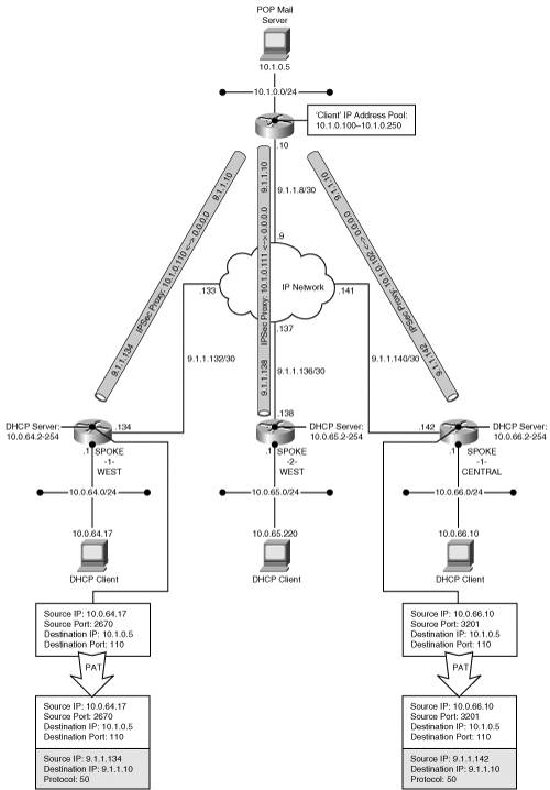
The pre-assigned address range allows each host to have a unique IP address. Having a unique IP address for each remote host eliminates the requirement to dynamically map-source ports on flows from the remote hosts. With PAT removed from the process, sessions may be initiated to the remote host’s well-known application ports, provided a route exists to the site. Recall that the route is dynamically created in the hub using Reverse Route Injection during the IPSec establishment.
Slight modifications are required to the configurations provided in Client Extension Mode. The hub must provide Reverse Route Injection for a remote site’s protected subnet in order to establish a return path for packets destined to that spoke’s hosts while the spoke must specify the use of Network Extension Mode in order to avoid receiving a dynamically assigned IP address from the hub. Examples 5-30 and 5-31 provide the configuration modifications required on the hub and spoke, respectively.
Example 5-30. Hub Configuration Supporting Network Extension Mode
vpn-gw1-west#show running-config
!
aaa new-model
!
aaa authentication login user-auth local
aaa authorization network group-auth local
!
! User authentication database
username cisco password 0 cisco123
username client-mode password 0 cisco123
!
crypto isakmp policy 3
 encr 3des
 authentication pre-share
 group 2
!
crypto isakmp keepalive 60 5
!
! IPSec Group Attributes (no IP address pool required)
crypto isakmp client configuration group client-mode
 key cisco123
 domain cisco.com
 idletime 3600
!
crypto ipsec transform-set client-transform esp-3des esp-md5-hmac
!
! Dynamic crypto map used for clients with Reverse Route Injection
crypto dynamic-map dyn-map 10
 set transform-set client-transform
 reverse-route
!
! Crypto map authentication and authorization methods defined
crypto map clientmap client authentication list user-auth
crypto map clientmap isakmp authorization list group-auth
crypto map clientmap client configuration address respond
crypto map clientmap 10 ipsec-isakmp dynamic dyn-map
!
ip route 0.0.0.0 0.0.0.0 9.1.1.9
Example 5-31. Spoke Configuration Requesting Network Extension Mode
spoke-1-central#show running-config
!
crypto ipsec client ezvpn remote
 group client-mode key cisco123
 mode network-extension
 peer 9.1.1.10
!
interface Ethernet0
 ip address 10.0.66.1 255.255.255.0
 hold-queue 100 out
!
interface Ethernet1
 ip address 9.1.1.142 255.255.255.248
 crypto ipsec client ezvpn remote
!
ip route 0.0.0.0 0.0.0.0 9.1.1.141
Note
Well-known ports are used for specific services on hosts and routers. Incoming connections must use these well-known ports in order to obtain service. As an example, an SMTP mail server uses the well-known TCP port of 25. Some services, such as VoIP, signal the port address in the call control messages. Modification of the source port through PAT will interfere with the end-to-end connection model and will likely prevent the establishment of the calls. Since Network Extension Mode does not modify the VoIP terminal’s IP address and port, IP telephony through IPSec VPNs may be simplified. Also note that remote IP telephony terminals may register with a server at the hub site such that the EzVPN connection is always established.
Example 5-32 provides the hub’s crypto map and routing state for SPOKE-1-CENTRAL in which emphasis is placed on the IPSec proxy and the static route. The IPSec proxy provides protection for traffic initiated from any remote host assigned a private address by the EzVPN router to any host at the hub site. The static route is dynamically inserted in the hub’s routing for the duration of the IPSec connection.
Example 5-32. Hub Crypto Map State for Network Extension Mode
vpn-gw1-west#show crypto map

Crypto Map "clientmap" 10 ipsec-isakmp
        Dynamic map template tag: dyn-map

Crypto Map "clientmap" 20 ipsec-isakmp
        Peer = 9.1.1.142
        Extended IP access list
            access-list permit ip any 10.0.66.0 0.0.0.255
            dynamic (created from dynamic map dyn-map/10)
        Current peer: 9.1.1.194
        Security association lifetime: 4608000 kilobytes/3600 seconds
        PFS (Y/N): N
        Transform sets={ client-transform, }
        Reverse Route Injection Enabled
        Interfaces using crypto map clientmap:
                Serial1/0

vpn-gw1-west#show ip route

Gateway of last resort is 9.1.1.9 to network 0.0.0.0
      9.0.0.0/30 is subnetted, 1 subnets
C        9.1.1.8 is directly connected, Serial1/0
      10.0.0.0/8 is subnetted, 2 subnets
C        10.1.0.0 is directly connected, FastEthernet0/1
S        10.0.66.0 [1/0] via 0.0.0.0, Serial1/0
S*    0.0.0.0/0 [20/0] via 9.1.1.9, 3w2d
Unfortunately, an IPSec connection cannot be initiated from the hub site to the remote site because the remote site’s public IP address may not be known a priori. The hub-and-spoke VPN can be dynamically built if each remote site router maintains an IPSec connection to the hub. A simple persistent connection initiated from a remote server to a server at the hub site will sustain the IPSec. Although the IPSec connection may expire, the remote server’s persistent connection will likely use a frequent polling mechanism to verify the state of the hub server. The polling mechanism will immediately reestablish the IPSec session, enabling access to the other servers at the remote site.
You have seen how the client connectivity models enable the dynamic creation of a simple hub-and-spoke VPN, greatly simplifying the configuration requirements at both the hub and spoke. In addition, aggregating each site’s route requirements into a single IPSec proxy statement minimizes the number of IPSec sessions. We initially provided a framework for building a hub-and-spoke VPN using the software client mode connection model. The client mode enabled connection capabilities for multiple clients at the remote site by embedding the client connection model in the remote site router. Finally, we enhanced the model with Network Extension Mode. The VPN is still dynamically built while using statically assigned private addresses for each of the sites. The elimination of Port Address Translation enables many more services on the VPN than otherwise. The Network Extension Mode leverages all of the scalability attributes of a client-connected model while providing the look and feel of a more traditional hub-and-spoke VPN.
The client connection model provides a reasonably scalable hub-and-spoke network. The number of simultaneously connected remote sites determines the scalability requirements of the hub in terms of IPSec SAs and IKE SAs. The use of Reverse Route Injection eliminates the requirement for establishing a private routing protocol connection between the hub and its spokes. Therefore, the hub is no longer burdened with maintaining routing state. The hub site may continue to use IKE dead peer detection or keepalive in order to validate the IPSec state for each of its connected remotes. The most common scalability constraint incurred by the hub is the volume of data passing through the device as transit traffic. The hub site must route traffic from each of the spokes and mostly likely will provide transit access to the Internet.
Most network traffic demands are driven by client–server connections that tend to be hub-and-spoke in nature. New peer-to-peer applications are slowly changing that paradigm. As these traffic demands increase, the spoke-to-spoke transit traffic passing through the hub becomes a performance constraint. Next, you’ll explore how full-mesh architecture addresses this connectivity requirement.
The full-mesh architecture establishes a direct IPSec connection between every site in the VPN. Effectively, every IPSec router in the VPN must serve as a hub for its site. A hub’s scalability constraints described in the previous sections still apply. The motivation for creating full-mesh VPN should be based on actual traffic demands requiring traffic between any site to any other site in the VPN. Assuming the traffic demands warrant the creation of a full-mesh IPSec VPN, we can consider several connectivity models that enable direct connections between the sites.
The simplest full-mesh connection model uses a simple IPSec connection between each site. Each IPSec connection requires a unique proxy statement that protects traffic between a specific set of VPN peers. If we assume that there are N routers terminating IPSec connections in the VPN, then each site will require a minimum of N-1 IPSec proxy statements. The IPSec connections may or may not be persistent; however, they must be defined in order to direct traffic to the appropriate remote VPN node. The total number of IPSec connections can be modeled as N(N-1)/2. Because an IPSec connection requires a proxy statement defined at each end, there are N(N-1) IPSec proxy statements defined in the VPN. Figure 5-9 shows the topology that is built with an IPSec full-mesh configured.

The full-mesh IPSec VPN router configuration looks equivalent to a hub node in a hub-and-spoke IPSec VPN. The configuration for VPN-GW1-WEST shown originally in the Example 5-1 hub-and-spoke configuration remains the same; however, there is no need for transit traffic protection. The SPOKE-1-WEST configuration shown in Example 5-3 is modified to accommodate direct IPSec connections between each of the other sites. The modified configuration is shown in Example 5-33.
Example 5-33. Native IPSec Full-Mesh Spoke Configuration
spoke-1-west #show running-config
!
hostname spoke-1-west
!
crypto isakmp policy 10
 hash md5
 authentication pre-share
 lifetime 3600
crypto isakmp key cisco address 9.1.1.10
crypto isakmp key cisco address 9.1.1.134
crypto isakmp key cisco address 9.1.1.138
crypto isakmp key cisco address 9.1.1.142
crypto isakmp key cisco address 9.1.1.146
crypto isakmp key cisco address 9.1.1.150
crypto isakmp keepalive 10
!
!
crypto ipsec transform-set esp-tunnel-internet esp-des esp-md5-hmac
!
! Crypto map for hub site peer
crypto map vpn 10 ipsec-isakmp
 set peer 9.1.1.10 set transform-set esp-tunnel-internet
 match address esp-tunnel-vpn-gw1-west
crypto map vpn 20 ipsec-isakmp
 set peer 9.1.1.134
 set transform-set esp-tunnel-internet
 match address esp-tunnel-spoke-2-west
crypto map vpn 30 ipsec-isakmp
 set peer 9.1.1.138
 set transform-set esp-tunnel-internet
 match address esp-tunnel-spoke-1-central
crypto map vpn 40 ipsec-isakmp
 set peer 9.1.1.142
 set transform-set esp-tunnel-internet
 match address esp-tunnel-spoke-2-central
crypto map vpn 50 ipsec-isakmp
 set peer 9.1.1.146
 set transform-set esp-tunnel-internet
 match address esp-tunnel-spoke-1-east
crypto map vpn 60 ipsec-isakmp
 set peer 9.1.1.150
 set transform-set esp-tunnel-internet
 match address esp-tunnel-spoke-2-east
!
interface Ethernet0
 ip address 10.0.64.1 255.255.255.0
!
interface Serial0
 ip address 9.1.1.130 255.255.255.252
 crypto map vpn
!
! default route to the backbone
ip route 0.0.0.0 0.0.0.0 9.1.1.129
!
! Protected address ranges from spoke to hub
ip access-list extended esp-tunnel-vpn-gw1-west
 permit ip 10.0.64.0 0.0.0.255 10.1.0.0 0.0.0.255
ip access-list extended esp-tunnel-spoke-2-west
 permit ip 10.0.64.0 0.0.0.255 10.0.65.0 0.0.0.255
ip access-list extended esp-tunnel-spoke-1-central
 permit ip 10.0.64.0 0.0.0.255 10.0.66.0 0.0.0.255
ip access-list extended esp-tunnel-spoke-2-central
 permit ip 10.0.64.0 0.0.0.255 10.0.67.0 0.0.0.255
ip access-list extended esp-tunnel-spoke-1-east
 permit ip 10.0.64.0 0.0.0.255 10.0.68.0 0.0.0.255
ip access-list extended esp-tunnel-spoke-2-east
 permit ip 10.0.64.0 0.0.0.255 10.0.69.0 0.0.0.255
end
As the size of the VPN increases, the configuration complexity increases with O(N^2). The full-mesh VPN gets even more interesting when one or more of the sites have a non-contiguous IP address range. A non-contiguous IP address range at one site requires a unique IPSec proxy statement defined between that site and all of the others, further adding to the complexity of the configuration. Each non-contiguous IP address range in the network effectively creates an additional site in the full mesh. This may be modeled as N(N-1)/2 + M(N-1) connections, where M represents the total number of non-contiguous IP address ranges in the VPN. Figure 5-10 highlights the new IPSec topology map with the addition of a non-contiguous IP address range at the hub site. Note that all the other sites require additional IPSec proxy statements to accommodate the non-contiguous IP address range.
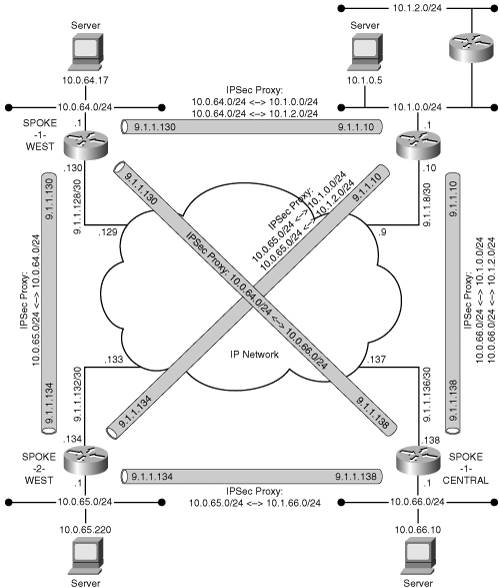
Thus far, we have addressed only the requirement for IPSec proxy statements, and have not addressed routing requirements. The task is simplified if you assume that the each of the sites uses a default route to the backbone. This is typically the case when building the VPN over the Internet. You may recall from the section regarding building hub-and-spoke VPNs that the IPSec proxy statement effectively replaces the routing functions as packets leave the router. As long as the backbone maintains proper routing paths between the IPSec endpoints, the backbone topology may be arbitrarily defined.
Internet access using this model can be achieved with either split tunneling or by directing all unknown destinations to a designated site in the VPN. Most enterprises avoid providing direct Internet access from each site in order to minimize the number of security exposure points. The enterprise will usually designate one site as the Internet access site where firewalls protect the entire VPN. Effectively, the Internet access site becomes a preferred hub in the full-mesh VPN for any unknown destination. Figure 5-11 shows the full-mesh IPSec VPN with a default hub for Internet traffic.
In this scenario, traffic flows originating and terminating within the VPN potentially match two IPSec proxy statements—the explicit one defined for intranet traffic and the generic one defined for Internet traffic. Obviously, the intranet profile should take priority over the Internet profile. If the priority is reversed, the VPN will operate as a hub-and-spoke, thereby negating the benefits of the site-to-site IPSec profiles. The priority of the proxy statements is determined by the order of the crypto map instances. Referring back to Example 5-33, we note that the IPSec proxy configuration on SPOKE-1-WEST explicitly defines the protection of specific subnets protected by remote peers. The configuration does not address protection of Internet-destined traffic that is not associated with any of the peers; therefore, Internet traffic is not protected by the IPSec crypto proxy statements.
The previous configuration for the spoke routers requires the addition of a default crypto map as the last in the sequence. Example 5-34 highlights the modifications required. The last crypto map serves as a crypto map of last resort, forcing Internet-bound traffic to the “hub” router in the full-mesh VPN. Note also that the more specific crypto map for the “hub” router’s protected address can be removed because it is redundant with the protection of all Internet traffic that is to transit the hub. The hub’s protected address range is in the aggregate range of the Internet. The hub router must still serve as a transit router for Internet traffic as shown previously in Example 5-9.
Example 5-34. Native IPSec Full-Mesh Spoke Configuration with Default
spoke-1-west #show running-config
!
hostname spoke-1-west
!
crypto isakmp policy 10
 hash md5
 authentication pre-share
 lifetime 3600
crypto isakmp key cisco address 9.1.1.10
crypto isakmp key cisco address 9.1.1.134
crypto isakmp key cisco address 9.1.1.138

crypto isakmp keepalive 10
!
!
crypto ipsec transform-set esp-tunnel-internet esp-des esp-md5-hmac
!
! IPsec Proxy sequence 10 removed for hub site. Refer to default below
crypto map vpn 20 ipsec-isakmp
 set peer 9.1.1.134
 set transform-set esp-tunnel-internet
 match address esp-tunnel-spoke-2-west
crypto map vpn 30 ipsec-isakmp
 set peer 9.1.1.138
 set transform-set esp-tunnel-internet
 match address esp-tunnel-spoke-1-central
! IPsec Proxy default for spoke-to-hub including Internet
crypto map vpn 70 ipsec-isakmp
 set peer 9.1.1.10
 set transform-set esp-tunnel-internet
 match address esp-tunnel-internet
!
interface Ethernet0
 ip address 10.0.64.1 255.255.255.0
!
interface Serial0
 ip address 9.1.1.130 255.255.255.252
 crypto map vpn
!
! default route to the backbone
ip route 0.0.0.0 0.0.0.0 9.1.1.129
!
! Protected address ranges from spoke to spoke
ip access-list extended esp-tunnel-spoke-2-west
 permit ip 10.0.64.0 0.0.0.255 10.0.65.0 0.0.0.255
ip access-list extended esp-tunnel-spoke-1-central
 permit ip 10.0.64.0 0.0.0.255 10.0.66.0 0.0.0.255
! Protected address range from spoke to hub including Internet
ip access-list extended esp-tunnel-internet
 permit ip 10.0.64.0 0.0.0.255 0.0.0.0 255.255.255.255
end
The full-mesh VPN is a highly desirable architecture when a large amount of traffic must be sent from any given site to all the other sites. Applications such as VoIP might drive this requirement even when the call control is located at a single site in the VPN. The bearer traffic for VoIP will want to follow the shortest path between two sites. With a full-mesh IPSec VPN, the VoIP-bearer traffic may avoid passing through a hub site where the traffic must be decrypted and subsequently re-encrypted. Another application that requires any-to-any connectivity is IP multicast. Unfortunately, the earlier implementations of IPSec were not designed to handle point-to-multiple traffic peers; therefore, this architecture does not handle multicast streams in the VPN.
In summary, the full-mesh IPSec VPN does allow site-to-site traffic to pass directly between the sites without having to traverse the hub. The advantages of any-to-any connectivity are offset by the additional configuration complexity required to build the full-mesh IPSec proxy statements. In addition, the improper assignment of IP address ranges will further complicate the configuration. We have also introduced additional scalability constraints in the VPN devices because every site must effectively become a hub for its protected address range. Every site must handle the maximum potential number of IKE and IPSec SAs necessary to reach every other site’s protected address space. A site with fewer simultaneous traffic demands to every other site might be able to use a less scalable device. This assumption is based on the premise that IKE and IPSec SAs are instantiated only when there are active traffic demands between the two peers.
Some IPSec equipment such as the Cisco VPN 3000 Series devices activate IKE and IPSec SAs once configured in the router. In contrast, the Cisco IOS based devices establish IKE and IPSec SAs only when traffic flows match the IPSec profiles. The tradeoff between the two models is a delay during tunnel establishment versus a permanently allocated resource for idle IPSec tunnels. The IOS devices must negotiate IKE and IPSec SAs prior to passing traffic between the sites. The VPN 3000 devices pre-negotiate the LAN-to-LAN SAs such that traffic may pass immediately through the IPSec tunnel. Clearly, the permanently established full-mesh of IPSec SAs creates a scalability constraint for platforms with limited memory.
There are many trade-offs that the network architect must consider when building the full-mesh VPN. In this chapter, you’ve seen a few of the more critical design elements. One of the most challenging aspects of full-mesh VPNs built with IPSec is managing the IPSec proxy statements as the VPN evolves. As new sites or IP subnets are added, all of the other sites must be configured to accommodate the address ranges and IPSec termination points. The next section explores the use of GRE to simplify some of the configuration aspects of the full-mesh IPSec VPN.
As you saw demonstrated in the hub-and-spoke architecture, IPSec-protected GRE tunnels simplify the IPSec proxy statements by aggregating traffic flows into a single source/destination IP address pair. The same principles apply to the full-mesh model in which IPSec protects GRE. Even IP multicast and non-IP routing protocols may leverage the IPSec-protected GRE tunnel. As the size of the VPN grows, the configuration complexity still increases as O(N^2); however, noncontiguous IP address ranges do not impact the IPSec proxy statements. The number of IPSec connections is bounded by N(N-1)/2. The configuration complexity is moved to the IP routing at each site. The protected IP address ranges are simply routed into the tunnels. In the absence of a dynamic routing protocol operating through the VPN tunnels, the number of static routes required is modeled as N(N-1) + M(N-1), where N is the number of sites in the VPN and M is number of non-contiguous IP address ranges at any site. The full-mesh VPN using static routes over IPSecprotected GRE tunnels is twice as complex as the native IPSec tunnel model because all the adjacencies must be configured in both the routing plane and the IPSec peer statements. You can simplify the routing configuration by applying a dynamic routing protocol over the GRE tunnels.
Now, to consider the impact of a dynamic routing plane through the GRE tunnels. The introduction of dynamic routing through the GRE tunnels minimizes the configuration complexity by eliminating the static routes. Assuming the routing protocol is capable of dynamically building routing adjacencies through the tunnels (for example, EIGRP, OSPF, and RIPv2), the only configuration needed is configuring the IPSec connections for the GRE tunnel endpoints and applying the routing protocol to the tunnel interface. Figure 5-13 shows how the routing is modified based on the association of a routing protocol to the tunnel interfaces.


Figure 5-13 highlights the fact that an IGP routing process will have to evaluate many potential paths when building the routing topology. Each router in the full-mesh VPN must build a shortest path tree that includes every path available between every router in the VPN. Of course, almost all of these paths are discarded because the router eventually converges on the path that is directly established between the two routers. In all likelihood, the loss of a direct path between two routers means that the remote peer is off the network and all the other potential paths are invalid as well. The full-mesh IGP topology places an extreme load on small VPN routers due to the computational complexity.
The configuration listing in Example 5-35 shows how the “spoke” with full-mesh connectivity requires a unique tunnel, crypto map, and access list for each peer in the network. The route process is bound to the entire set of tunnel interfaces such that protected addresses are dynamically propagated and learned through the tunnels. The explicit route statements are required in order to avoid recursive routing loops because the hub will propagate a default route to the spoke via Tunnel0.
Example 5-35. Full-Mesh GRE Spoke Configuration with Dynamic Routing and Default Route via the Hub
spoke-1-west#show running-config
!
crypto isakmp policy 10
 hash md5
 authentication pre-share
 lifetime 3600
crypto isakmp key cisco address 9.1.1.10
crypto isakmp key cisco address 9.1.1.134
crypto isakmp key cisco address 9.1.1.138
crypto isakmp keepalive 10
!
crypto ipsec transform-set esp-tunnel-internet esp-des esp-md5-hmac
 mode transport
!
crypto map vpn 10 ipsec-isakmp
 set peer 9.1.1.10
 set transform-set esp-tunnel-internet
 match address gre-tunnel-vpn-gw1-east
crypto map vpn 20 ipsec-isakmp
 set peer 9.1.1.134
 set transform-set esp-tunnel-internet
 match address gre-tunnel-spoke-2-west
crypto map vpn 30 ipsec-isakmp
 set peer 9.1.1.138
 set transform-set esp-tunnel-internet
 match address gre-tunnel-spoke-1-central
!
interface Ethernet0
 ip address 10.0.64.1 255.255.255.0
!
interface Tunnel0
 ip unnumbered Ethernet0
 tunnel source 9.1.1.130
 tunnel destination 9.1.1.10
 crypto map vpn
interface Tunnel1
 ip unnumbered Ethernet0
 tunnel source 9.1.1.130
 tunnel destination 9.1.1.134
 crypto map vpn
interface Tunnel2
 ip unnumbered Ethernet0
 tunnel source 9.1.1.130
 tunnel destination 9.1.1.138
 crypto map vpn
!
interface Serial0
 ip address 9.1.1.130 255.255.255.252
 crypto map vpn
!
router eigrp 100
 network 10.0.64.0 0.0.0.255
!
ip route 9.1.1.10 255.255.255.252 9.1.1.129
ip route 9.1.1.132 255.255.255.252 9.1.1.129
ip route 9.1.1.136 255.255.255.252 9.1.1.129
!
ip access-list extended gre-tunnel-vpn-gw1-east
 permit gre host 9.1.1.130 host 9.1.1.10
ip access-list extended gre-tunnel-spoke-2-west
 permit gre host 9.1.1.130 host 9.1.1.134
ip access-list extended gre-tunnel-spoke-1-central
 permit gre host 9.1.1.130 host 9.1.1.138
The simplification of this configuration does not come without a cost. With dynamic routing through the tunnels, the routing adjacencies and IPSec SAs are always established. This requires every site to have its entire set of configured IPSec SAs active. In addition, the routing adjacencies require state management that places additional processing burdens on the processor. These routing design constraints are similar to those incurred when implementing a full-mesh VPN using a classic FR/ATM network. The number of routing and IPSec adjacencies that any given site can simultaneously maintain provides an upper bound for the size of the VPN. The route calculation functions are fairly processor intensive, especially given the number of shortest path trees that a router must evaluate. Dynamic routing protocols such as EIGRP and OSPF provide a rapid means of convergence and fault detection. A large full-mesh network with link-state routing protocols is sensitive to IPSec failures. An excessively large number of routers and paths may extend the initialization or convergence time, making the network unusable. Extreme caution is advised when designing a full-mesh network that approaches one of the router’s maximum limits (for example, IKE, IPSec, routing adjacencies, or interfaces).
The full-mesh IPSec-protected GRE network does support Internet access with or without split tunneling. Split tunneling allows the IPSec tunnel endpoints to use the default route to the backbone whereas the private addresses are propagated using dynamic routing over the GRE tunnels. A design that does not use split tunneling requires propagation of the default route from the designated Internet access router. Other routers that receive the default route through the GRE tunnel will need a more explicit path for their IPSec peer IP address that does not use the GRE tunnel in order to avoid recursive routing.
The next chapter presents methods for building more scalable IPSec networks that take advantage of dynamic routing topology. It is evident at this point that the persistent full-mesh of IGP neighbor establishment should be avoided. Likewise, you will have to address the routing protocols limitations with the breadth and depth of the shortest path tree calculations in order for the system to scale to hundreds or thousands of sites.
One of the most challenging aspects of designing an IPSec VPN is choosing an appropriate architectural model. This chapter has presented a variety of architectural models in order to highlight the advantages and disadvantages of each. When selecting one model over another, network designers must choose among tradeoffs, paying close attention to simplification of the configuration and processing efficiency. The combination of these two attributes enables the design of scalable IPSec VPNs. It is also notable that the architectural models are not necessarily mutually exclusive. A large VPN is likely to have different service requirements when comparing large branch offices to small branch offices. For example, the network architect may elect to use a client connectivity model for small home offices while using hub-and-spoke GRE-protected tunnels for large branch office sites. In fact, these functions may be integrated on a single hub platform. Of course, the aggregate requirements must be met on the integrated platform. Integration of various architectural models on a common platform may be necessary for smaller VPNs. In contrast, dedicating a VPN gateway for each architectural model may be economically justified within a large VPN in order to enable scalability. Now that you have seen how to design large-scale VPNs, reliability of the VPN is of paramount importance. In the next chapter, you’ll be introduced to methods for achieving fault tolerance in the architectural models discussed in this chapter.