
In Chapter 5, “IPSec VPN Architectures,” you saw various IPSec VPN architectural models. The IPSec VPN configuration can become quite complex with any architecture, especially as the number of IPSec endpoints becomes significantly large. In this chapter, you will examine mechanisms to alleviate the configuration complexity of a large-scale IPSec VPN. The principle advantage of these mechanisms is the dynamic creation of the IPSec security associations without requiring pre-defined IPSec proxy profiles. This attribute is particularly important when building large full-, partial-, or temporal-mesh topologies. In this chapter, you will explore two mechanisms used to automate the configuration of IPSec VPNs
Tunnel Endpoint Discovery (TED)
Dynamic Multipoint VPN (DMVPN)
The TED model enables the establishment of native IPSec tunnel connections across an IP cloud while the DMVPN model leverages the IPSec transport of multi-protocol GRE packets. In the next sections, you’ll take a closer look at the two models.
Traditional IPSec VPN configuration on a Cisco IOS router requires the static configuration of the IPSec peer endpoints via crypto maps. As the name suggests, Tunnel Endpoint Discovery (TED) allows for an IPSec peer to dynamically discover the corresponding IPSec peers. The TED model provides a scalable approach to dynamically building IPSec VPNs based on standard routing protocols. The benefits of using TED include the following:
Simplified crypto configuration
Dynamic crypto maps eliminating a priori peer configuration
IPSec protection built on demand
With TED, the initiating router dynamically determines an IPSec peer for secure IPSec communications. To configure a large, fully meshed network without TED, each peer must have static crypto maps to every other peer in the network. For example, if there are 100 peers in a large, fully meshed network, each router needs 99 static crypto maps, one for each of its peers. With TED, only a single dynamic crypto map with TED enabled is needed because the other peers are discovered dynamically. Thus, static crypto maps do not have to be configured for each peer, which significantly simplifies the configuration.
Let’s take a look at the operation of TED using the network topology described in Figure 7-1. The TED mechanism uses the inherent routing topology of the network to discover tunnel endpoints for prefixes that need to be protected. This means that the protected source and destination IP prefixes must be routable in the backbone between the two IPSec endpoints. The sequence outlined in the following steps is necessary to discover the remote peer endpoints and policies associated with each endpoint:
In this example, HOST-1-WEST sends an IP packet destined to HOST-2-WEST. Assume also that IP reachability information is available in all the routers shown in the figure for all destination subnets. The IP packet is routed to SPOKE-1-WEST where TED is configured on the egress interface destined to HOST-2-WEST. IPSec policy configured on SPOKE-1-WEST identifies that the packet destined to HOST-2-WEST needs to be encrypted, but there is no SA (security association) associated with this.
SPOKE-1-WEST sends a TED probe with a source address of HOST-1-WEST and a destination address of HOST-2-WEST. The TED probe is an IKE message with UDP source and destination port 500. The probe has the following payloads:
Vendor payload—Cisco vendor ID
ID Endpoint Payload—ID, encoded as IP address (SPOKE-1-WEST’s IP address)
ID Proxy Payload—The proxy address (HOST-1-WEST’s subnet derived from the IPSec proxy configured)
The TED probe is intercepted by SPOKE-2-WEST. The TED probe is an IPSec packet that matches the crypto proxy policy defined by an ACL on SPOKE-2-WEST. The intercepting router knows the packet should have been encrypted based on its IPSec policy; however, it also knows that TED is configured. As a result, the router evaluates the packet and determines that it is a probe packet that conforms to the IPSec proxy policies designed to protect the hosts behind SPOKE-2-WEST. SPOKE-2-WEST determines that the flow from HOST-1-WEST to HOST-2-WEST should be protected. The SPOKE-2-WEST then sends a TED reply. The TED response has the SPOKE-2-WEST’s IKE identity and the IP subnet that is associated with the IPSec proxy protecting the HOST-2-WEST.
When SPOKE-1-WEST receives the TED response, it reads the ID payloads to get the peer’s (SPOKE-2-WEST’s) IKE identity IP address, and the peer’s half of the IPSec proxy.
SPOKE-1-WEST initiates IKE to SPOKE-2-WEST and follows the usual IKE exchange to establish the IKE and IPSec SAs between the peers.

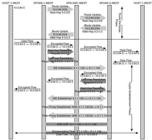
The sequence of events described in the previous numbered list emphasizes the discovery process of TED between two IPSec gateways. Figure 7-2 shows where the Tunnel Endpoint Discovery process occurs relative to the traditional routing updates, IKE initialization, and IPSec data transfer.
Although TED reduces configuration complexity and enables dynamic discovery of IKE endpoints in large-scale IPSec VPN deployments, it has several limitations.
The most critical limitation with the TED mechanism is the assumption that routing information for every protected subnet behind each VPN gateway is available in every routing node between the IPSec endpoints. As you learned in previous chapters. One of the biggest motivations for an IPSec VPN is the cost savings reaped by building a VPN over a public network such as the Internet. Typically, the private protected subnets use private addresses (RFC 1918) that are not reachable over a public network. If an IPSec VPN is deployed using private addresses that are not routable across the public network, TED cannot be used because the probe and response packets rely on end-to-end reachability of the source and destination hosts in the private subnets. In IPSec deployments without this limitation (for example, in MPLS/VPN or Frame Relay networks), TED can be quite useful in reducing the configuration complexity.
Some other limitations with TED are:
The crypto proxy configurations must adequately represent the address space (both source and destination) that will be protected; therefore, that address space must be known in advance.
The destination may be represented as “all” routes while the source must represent the address space that the VPN gateway is protecting.
Because the peer is not known at the time of configuration, key management must also be addressed. One option is to use a pre-shared key that is consistent across all VPN gateways in the network. The other alternative is to use a PKI system to dynamically create the key material between the peers.
Note
The creation of IPSec SAs requires the presence of viable VPN routes throughout the network, including the backbone. The TED proxy profiles must not include protection of the VPN routing updates to backbone routers between the IPSec gateways because these backbone routers must be able to process the routing updates. Most routing protocols, such as OSPF or EIGRP, use a multicast or broadcast address to establish adjacencies and send routing updates; these addresses are typically excluded from the IPSec proxy policy. Therefore, inadvertent encryption of the routing protocol between the TED end-point and the next-hop gateway is usually not an issue. Special care must be taken when BGP is used as it relies on unicast to establish neighbor adjacencies.
Figure 7-2 highlighted the establishment of a direct IPSec relationship between SPOKE-1-WEST and SPOKE-2-WEST using TED. The listing in Example 7-1 shows the necessary configuration elements.
Example 7-1. SPOKE-1-WEST Configuration for TED
spoke-1-west#show running-config

!
crypto isakmp policy 10
 authentication pre-share
crypto isakmp key cisco address 0.0.0.0 0.0.0.0
crypto isakmp keepalive 10
!
crypto ipsec transform-set ted-transform esp-des esp-md5-hmac
!
crypto dynamic-map ted-map 10
 set transform-set ted-transform
 match address ted
!
!
crypto map tedtag 10 ipsec-isakmp dynamic ted-map discover
!
interface FastEthernet0/0
 ip address 10.0.64.1 255.255.255.0
 duplex half
 speed 100
!
interface Serial1/0:0
 ip address 9.1.1.130 255.255.255.252
 crypto map tedtag
!
ip route 0.0.0.0 0.0.0.0 9.1.1.129
!
ip access-list extended ted
 permit ip 10.0.64.0 0.0.0.255 10.0.0.0 0.255.255.255
!
Note that the TED configuration does not require the configuration of each IPSec peer relationship. The IPSec SA is dynamically established after traffic matches the IPSec proxy on the backbone uplink interface. Let’s assume that the traffic is initiated from the host (10.0.64.5), behind SPOKE-1-WEST, to the host (10.0.65.5), behind SPOKE-2-WEST. The backbone routing protocol must create a path for the destination that forwards the traffic over the interface where IPSec protection is applied. The IP route table listing in Example 7-2 shows that the route process will forward the traffic over the serial interface where the crypto map is applied.
Example 7-2. Routing State for SPOKE-1-WEST
Spoke-1-west#show ip route

     9.0.0.0/8 is variably subnetted, 1 subnets, 1 masks
C       9.1.1.128/30 is directly connected, Serial1/0:0
     10.0.0.0/8 is variably subnetted, 1 subnets, 1 masks
C       10.0.64.0/24 is directly connected, FastEthernet0/0
S*   0.0.0.0/0 [1/0] via 9.1.1.129
You can see that the routing table will force traffic destined to 10.0.65.0 out the serial interface where the crypto map is applied. Example 7-3 shows the crypto map state on the serial interface before and after the establishment of SAs between the VPN gateways.
Example 7-3. Spoke IPSec Security Association
spoke-1-west#show crypto map
Crypto Map "tedtag" 10 ipsec-isakmp
            Dynamic map template tag: ted-map
            Discover enabled
            Serial1/0:0

... After IPSec Establishment ...

spoke-1-west#show crypto map
Crypto Map "tedtag" 10 ipsec-isakmp
            Dynamic map template tag: ted-map
            Discover enabled


Crypto Map "tedtag" 20 ipsec-isakmp
            Peer = 9.1.1.134
            Extended IP access list
                access-list permit ip 10.0.64.0 0.0.0.255 10.0.65.0 0.0.0.255
                dynamic (created from dynamic map ted-map/10)
            Current peer: 9.1.1.134
            Security association lifetime: 4608000 kilobytes/3600 seconds
            PFS (Y/N): N
            Transform sets={ ted-transform, }
            Interfaces using crypto map tedtag:
            Serial1/0:0
The recipient node of the TED request (SPOKE-2-WEST) establishes a corresponding IPSec proxy state such that return traffic will be directed to the appropriate initiating router. Recall that SPOKE-2-WEST has an aggregate IPSec proxy defined as 10.0.65.0 -> 0.0.0.0. If this aggregate were used solely for SPOKE-1-WEST, any traffic leaving SPOKE-2-WEST would have to be directed solely to SPOKE-1-WEST. Clearly, that is not the goal, as each spoke should be able to pass traffic to any number of peers. The originating IKE connection specifies that SPOKE-1-WEST is only providing protection for the subnet 10.0.64.0/24; therefore, SPOKE-2-WEST installs only a subset of its IPSec proxy (that is, 10.0.65.0/24 -> 10.0.64.0/24). This restriction allows any subsequent request from a different peer to establish the appropriate IPSec proxy statement that does not overlap with the IPSec proxy established between SPOKE-1-WEST and SPOKE-2-WEST. The listing in Example 7-4 shows the crypto IPSec SA on SPOKE-1-WEST after the establishment of the IPSec SA. Note the explicit IPSec proxy profile defined between SPOKE-1-WEST and SPOKE-2-WEST.
Example 7-4. TED Recipient IPSec Crypto State
spoke-1-west#show crypto ipsec sa

interface: Serial1/0:0
    Crypto map tag: tedtag, local addr. 9.1.1.130

   local  ident (addr/mask/prot/port): (10.0.64.0/255.255.255.0/0/0)
   remote ident (addr/mask/prot/port): (10.0.65.0/255.255.255.0/0/0)
   current_peer: 9.1.1.134
     PERMIT, flags={}
    #pkts encaps: 4, #pkts encrypt: 4, #pkts digest 4
    #pkts decaps: 4, #pkts decrypt: 4, #pkts verify 4
    #pkts compressed: 0, #pkts decompressed: 0
    #pkts not compressed: 0, #pkts compr. failed: 0, #pkts decompress failed: 0
    #send errors 0, #recv errors 0

     local crypto endpt.: 9.1.1.130, remote crypto endpt.: 9.1.1.134
     path mtu 1500, media mtu 1500
     current outbound spi: 17339A3B

     inbound esp sas:
      spi: 0x52B2154D(1387402573)
        transform: esp-des esp-md5-hmac ,
        in use settings ={Tunnel, }
        slot: 0, conn id: 2000, flow_id: 1, crypto map: tedtag
        sa timing: remaining key lifetime (k/sec): (4607998/3489)
        IV size: 8 bytes
        replay detection support: Y

     inbound ah sas:

     inbound pcp sas:

     outbound esp sas:
      spi: 0x17339A3B(389257787)
        transform: esp-des esp-md5-hmac ,
        in use settings ={Tunnel, }
        slot: 0, conn id: 2001, flow_id: 2, crypto map: tedtag
        sa timing: remaining key lifetime (k/sec): (4607999/3489)
        IV size: 8 bytes
        replay detection support: Y

     outbound ah sas:

     outbound pcp sas:
Note
The IPSec proxy established between two TED endpoints is the logical intersection between the two proxies defined at either end. The initiator has a proxy profile that includes protection of many more remote addresses than the receiver protects. Likewise, the receiver has a proxy profile that includes protection of many more sources than the receiver protects. Typically, the receiver’s IPSec proxy policy must be an inverse superset of the initiator’s proxy policy in order to accept the proposal. TED allows the receiver to accept the initiator’s IPSec proxy policy despite the fact that it is a superset of the receiver’s IPSec proxy policy. The receiver’s TED process reconciles the discrepancy between the two IPSec proxy policies by identifying a non-mutually exclusive IPSec proxy policy that is a subset of both the initiator’s and the receiver’s IPSec proxy policy.
We note that the existence of multiple connections from unique peers requires the instantiation of a unique IPSec proxy for each peer. Over time, each peer will dynamically build IPSec state for traffic flows that match a full mesh. With minimal configuration, the TED method is able essentially to provide fully meshed network connectivity. The TED solution is also able to conserve resources, as you will establish IPSec SAs only between gateways that sustain user data traffic flows. In addition, the IPSec SAs may expire after a period of inactivity, thereby preserving memory in the security association database. Next, you’ll investigate what happens when the routing state of the backbone network changes such that the IPSec state is no longer valid.
The establishment of TED IPSec SAs clearly makes use of the current state of the backbone routing topology. Note that an interesting situation may occur when routing topology changes. There are two cases that should be considered: routing topology changes between the IPSec endpoints and routing topology changes around the IPSec endpoints. The TED process uses IPSec tunnel mode to encapsulate the protected traffic; therefore, the encrypted traffic uses the IPSec VPN gateway encapsulating addresses to route the packets across the backbone.
In the first scenario (that is, backbone topology change), the IPSec-encapsulated packets will simply follow an alternate path to reach the same IPSec peer endpoint. Assuming the convergence interval of the backbone is short enough, the IPSec IKE process will not detect the loss of the peer, and the IPSec session state will be sustained. A more interesting situation occurs when the backbone routing topology changes such that optimal path to the destination host is no longer through the same VPN gateway. If an alternate remote peer router advertises the protected address space, the originating router will continue to send data using the existing crypto SPI (security parameter index) to the original remote peer router. The alternate router will not receive the packets because it has no crypto state and is not the remote peer defined by the tunneling header. Only when return packets from the remote site invoke a probe packet from the alternate remote VPN gateway, is it possible for the responding host’s packets to return to the initiating host. Let’s take a look at the topology described in Figure 7-3.

Assume that the primary path to the subnet 10.1.2.0/24 from the backbone network is via VPN-GW1-WEST. When HOST-1-WEST needs to establish a connection to a host on 10.1.2.0/24, SPOKE-1-WEST initiates a TED probe to target the host on 10.1.2.0/24. The TED probe follows the primary route to VPN-GW1-WEST. The VPN-GW1-WEST subsequently responds to SPOKE-1-WEST indicating that an IPSec proxy should be established between the two gateways protecting traffic between 10.0.64.0/24 and 10.1.0.0/16. Once the IPSec SA is established, SPOKE-1-WEST encapsulates the packets using the designated identities (9.1.1.130 <-> 9.1.1.22). If a routing change occurs such that the backbone now routes packets to 10.1.2.0/24 to VPN-GW2-WEST, you have an interesting dilemma. For traffic leaving SPOKE-1-WEST, there may be no routing change. Therefore, SPOKE-1-WEST may continue to direct packets from 10.1.2.0 to VPN-GW1-WEST. If the LAN interface of VPN-GW1-WEST is down, the packets will be dropped for lack of a viable path to the destination host.
Note
The remote peer receiving the packet may decrypt the packet and may have discovered an alternate route to the destination via the backbone (that is, forwarding the packet back out the same interface from which it came); however, the IPSec policy on this remote peer does not provide protection for packets sourced from addresses other than those on its associated LAN.
Only when return traffic from the 10.1.2.0/24 subnet forces VPN-GW2-WEST to issue a TED probe to SPOKE-1-WEST does SPOKE-1-WEST realize a new IPSec SA is being requested. SPOKE-1-WEST may now respond to VPN-GW2-WEST with the appropriate IPSec proxy information such that the two gateways may establish a replacement IPSec SA.
Clearly, there are scenarios in which traffic flows may be interrupted while routing gateways try to determine a more appropriate TED path. The scenario described previously is typically rectified quickly because clients and servers with persistent connections (such as TCP connections) will periodically retry the connection before closing the session. Application connection retries in both directions force the discovery of a new TED path. In scenarios in which clients do not maintain persistent TCP connections to the servers (for example, HTTP, POP3, SMTP, and others), the servers never initiate connections to the clients. Scenarios using applications such as these will lead to long periods of lost connectivity. If the remote peer is still accessible but the hosts behind the peer are inaccessible, the TED state can lead to a persistent “black hole,” in which packets are persistently dropped. The situation is only rectified when IKE expires and the initiator establishes a new IKE session. This will lead to the discovery of the alternate peer and will restore the data path between the hosts.
In summary, TED is a reasonable method for dynamically establishing partial- and full-mesh IPSec topologies. It significantly simplifies configuration and allows for redundant topologies with a reasonably quick convergence interval. The one major limitation of TED is that the protected subnet address ranges must be routable in the backbone between the IPSec endpoints, a situation that is not feasible when the protected subnets are private IP networks that are not routable across public networks such as the Internet. Dynamic Multipoint VPN (DMVPN), discussed in the next section, addresses other limitations of TED.
One of the major motivations for building IPSec VPNs is their ability to have sites of an enterprise connected to each other over the public Internet. You studied various IPSec VPN architectures in Chapter 5, “IPSec VPN Architectures,” and saw that, for large VPNs with hundreds of sites, a full-mesh IPSec architecture has serious scaling limitations. Next-best alternatives to the full-mesh model are hub-and-spoke or partial-mesh models, as long as traffic patterns between sites are well known in advance. Given that the Internet has become ubiquitous, many large enterprises are building IPSec VPNs over the public Internet and have growing demands for dynamic spoke-to-spoke communication. For such enterprises, it would be desirable to establish direct spoke-to-spoke connectivity over IPSec on demand rather than transit the hub. This connectivity is exactly what DMVPN enables.
The DMVPN model provides a scalable configuration for a dynamic-mesh VPN based on the premise that the only relationships configured are those between the hub and spokes. The DMVPN architecture dynamically establishes a routable path via a GRE over IPSec connection between any two members in the DMVPN subnet. The destination prefixes and their next hops are discovered through traditional routing protocols while GRE tunnel endpoints are dynamically discovered and the IPSec protection policy of the tunnels is inferred from the tunnel source and tunnel destination. DMVPN uses a combination of a Multipoint GRE (mGRE) interface and Next Hop Resolution Protocol (NHRP) to achieve its objectives. The topology shown in Figure 7-4 describes DMVPN.
DMVPN introduces several new functional components that you must review in order to understand the process of connection establishment. The three key functional components are as follows:
Multipoint GRE interfaces
Next Hop Resolution Protocol
IPSec Proxy Instantiation
The next few sections present the characteristics for each of these functional components, and describe their value. Then, we illustrate how the functional components work together to create a scalable VPN.
Chapter 5, “IPSec VPN Architectures,” discussed the GRE model for hub-and-spoke IPSec VPNs and conveyed that the hub site uses statically defined point-to-point GRE tunnel interfaces for each spoke. This requirement of a unique GRE tunnel interface on the hub for each spoke limits the scalability of this model. Each tunnel interface in Cisco IOS consumes a data struc-ture known as an Interface Descriptor Block (IDB), which limits the scalability of this model. Another limitation of the traditional GRE model is that the IP address of the GRE tunnel endpoint on the spokes needs to be known in advance and this is a problem for spokes that use a dynamic address allocation from the backbone provider. Multipoint GRE (mGRE) solves both these problems.
As the name suggests, mGRE is a point-to-multipoint interface, in which a single tunnel interface can terminate all the GRE tunnels from all the spokes. This efficiency eliminates a great deal of configuration complexity and memory resource allocation. Second, it allows incoming GRE tunnel connections from any peer, including those with dynamically assigned tunnel addresses. The single multipoint tunnel interface dramatically simplifies the configuration of the hub in a hub-and-spoke VPN whereas a low-end platform may now participate in a temporal full-mesh topology. For the moment, we’ll ignore the IPSec protection requirement in order to highlight the GRE configuration aspects. The listing in Example 7-5 shows the traditional GRE model in which a unique point-to-point GRE interface configuration is required on the hub to establish connections for the spokes. Contrast this configuration with the listing in Example 7-6, where the mGRE tunnel interface is used.
Example 7-5. Hub Site with Point-to-Point GRE Interfaces
interface Tunnel0
 ip address 9.0.0.1 255.255.255.252
 no ip redirects
 ip mtu 1420
 ip ospf metric 10
 ip ospf priority 2
 delay 1000
 tunnel source Serial0/0
 tunnel destination 9.1.1.130


interface Tunnel1
 ip address 9.0.0.5 255.255.255.252
 no ip redirects
 ip mtu 1420
 ip ospf metric 20
 ip ospf priority 2
 delay 1000
 tunnel source Serial0/0
 tunnel destination 9.1.1.134
Example 7-6. Hub Site with Multipoint GRE Interface
interface Tunnel0
 ip address 9.0.0.1 255.255.255.0
 no ip redirects
 ip mtu 1420
 ip ospf network broadcast
 ip ospf priority 2

 delay 1000
 tunnel source Serial0/0
 tunnel mode gre multipoint
Notice that the hub configuration in Example 7-6 uses a single mGRE interface, thereby eliminating the replication of the tunnel interface configuration in the hub for each spoke. Clearly, the multipoint GRE interface configuration is much more scalable for provisioning, which is particularly valuable when the size of the hub-and-spoke VPN is very large. The mGRE interface consumes a single IDB, which conserves interface memory structures and interface process management on the hub.
The use of a multipoint interface does create a dilemma, however. Notice in Example 7-5 that each tunnel interface on the hub is configured with a tunnel source and tunnel destination IP address; these addresses are routable between the GRE endpoints. In contrast, notice in Example 7-6, which uses the mGRE interface on the hub, that a tunnel source address is configured under the mGRE interface but there is no tunnel destination address. Therefore, a mechanism to identify the remote peer’s tunnel endpoint address is required with this scheme. This address resolution is performed by the Next Hop Resolution Protocol (NHRP). The fact that DMVPN does not need to know the remote tunnel endpoint IP address in advance is a compelling advantage for building site-to-site hub-and-spoke VPNs in which the spoke’s IP address is dynamically assigned. Dynamic IP address assignment is commonly used in dial, DSL, and cable access networks.
A second important point of contrast between the two configurations is the association of a private subnet with the GRE interface. With a point-to-point GRE model, each tunnel may have a unique IP subnet defined. A unique tunnel subnet allows more granular control over the routing processes that are assigned to each tunnel. In Example 7-6, we might associate different Open Shortest Path First (OSPF) cost metrics with each tunnel interface. In practice, the Multipoint GRE interface is associated with a large subnet. The Multipoint GRE interface does not provide a simple means of differentiating routes received from various spokes connected to this subnet because the routing metric used to reach any remote peer is based on the local mGRE interface’s assigned metric. To influence the path taken (that is, to determine which peer will be used for prefixes with the same destination), the operator must create route maps or routing filter lists that must be associated with specific peers or prefixes in order to influence the metrics for routes received.
Recall that a GRE interface has two local addresses—the GRE tunnel’s interface source IP address, used for routing in the public backbone, and the GRE tunnel’s assigned private IP address used for routing in the private and protected network. If the GRE tunnel’s source address is associated with an egress interfaces that uses a dynamically assigned IP address, then the GRE tunnel source IP address will also use the dynamically assigned IP address. Example 7-7 shows a tunnel interface bound to an egress interface in which the egress interface uses dynamically allocated IP addresses.
Example 7-7. GRE Interface with Logical Interface Sources
interface Serial0
ip address negotiated
 encapsulation ppp

interface Tunnel0
 ip address 9.0.0.1 255.255.255.0
 no ip redirects
 ip mtu 1416
 delay 1000
 tunnel source Serial0
 tunnel mode gre multipoint
 tunnel key 999
Dynamic routing updates advertised from the GRE interface will reference the Multipoint GRE interface’s assigned private IP address as the next hop. These routing updates may be propagated to the hub router where the spoke’s private subnet is inserted in the hub router’s route table with the spoke’s private GRE interface IP address as the next hop. But how does the hub know which IP encapsulation header to use for packets destined to the private IP destination associated with that particular spoke? The hub has the route prefix and the GRE next hop, but it isn’t able to discern the public IP address associated with the spoke’s Multipoint GRE interface. To address this situation, the hub’s adjacency database must locate the remote peer’s public IP address that is associated with that spoke’s assigned GRE tunnel IP address. To enable this, you must resolve the GRE tunnel private next-hop address to a publicly routable destination address. You can do this by using the Next Hop Resolution Protocol.
In the DMVPN model, each spoke has a protected IP address space that is not initially known by any other router in the VPN. First, you must provide a means of informing all the other spokes (and the hub) of the subnets that each spoke protects. Assuming that the hub router will have a permanent public IP address (that is, an IKE identity), then each of the spokes may be pre-configured to connect to the hub at boot time. The spokes may then initiate a connection to the hub, register with the hub, and inform the hub of the address space that each spoke protects. The objective of the routing process is to inform the hub and all the spokes of the private routable prefixes and the associated spoke’s Multipoint GRE (mGRE) interface for each prefix.
Note
The two typical routing models used within enterprises are the distance vector routing algorithms (such as RIP and EIGRP) and link state routing algorithms (such as OSPF and ISIS). Distance vector routing protocols require the specification of no split-horizon in order for the updates to be redistributed back to the Multipoint GRE interface at the hub from which the updates arrived. Link state routing protocols will automatically reflect the appropriate next hop within the subnet.
Note
Typically, OSPF would be configured in a point–multipoint mode on the mGRE interface. The DMVPN cloud must be treated as a broadcast environment such that the spokes install routes to the destination prefixes via the appropriate spokes. The use of OSPF in a point–multipoint mode causes host routes to be installed on the spokes with the next hop defined as the hub. The insertion of hub address as the next-hop for the other spoke’s prefix obviously negates the point of building the DMVPN network topology.
The routing updates provide the hub and each spoke with the appropriate next-hop address for the mGRE interface associated with each prefix. Figure 7-5 shows the logical multipoint subnet and the associated routing database.
You can see from Figure 7-5 that the hub routing database refers only to a remote spoke’s configured mGRE interface as the next hop for a given prefix. The Routing Information Base next-hop entry is not the dynamically assigned public IP address of the spoke. You need a mechanism to resolve the remote spoke’s mGRE interface to the remote spoke’s public IP address in order to establish an IKE security association. The Next Hop Resolution Protocol (NHRP) established between the hub and spoke will play a role in this adjacency reconciliation.
The NHRP protocol established between the spoke and the hub provides the necessary “glue” to associate a spoke’s public IP address with its configured private mGRE interface address. When the spoke initiates a connection to the hub, it registers with the hub via NHRP. The registration process at the hub binds the spoke’s mGRE interface to that spoke’s dynamically assigned public IP address. The hub now has an adjacency database for the all the active spokes in the entire DMVPN. This information is not broadcast to the active spokes; however, the spokes recognize that the hub serves as the adjacency database. Next, we’ll illustrate how NHRP works with an example.
Assume that SPOKE-1-WEST needs to establish a connection to another spoke, such as SPOKE-2-WEST. The originating spoke (SPOKE-1-WEST) knows that SPOKE-2-WEST’s private route prefix exists (in this case, it is 10.0.65.0/24) and also knows the remote spoke’s mGRE address as the next hop (in this case, 9.0.0.3). SPOKE-1-WEST does not know SPOKE-2-WEST’s public IP address (which is 9.1.1.134). In order to gain this information, SPOKE-1-WEST queries the hub for the tunnel endpoint adjacency information. The hub will respond with the appropriate public IP address associated with SPOKE-2-WEST’s mGRE next hop.
Figure 7-6 shows the sequence of events necessary to establish the connections between the spokes and the hub of the DMVPN cloud. When the hub-and-spoke topology is established, the routing processes are able to inform the spokes of all the accessible prefixes behind the other spokes. Figure 7-7 shows the information exchange process necessary for the spokes to establish a bidirectional tunnel with another spoke.
The originating spoke (that is, SPOKE-1-WEST) now has sufficient information to dynamically create a GRE tunnel instance to the remote spoke. The GRE tunnel instance will build an IP header with the tunnel source defined as the local spoke’s public IP address (9.1.1.130) and the tunnel destination defined as the remote spoke’s public IP address (9.1.1.134). Both of these addresses are routable on the IP backbone whereas the mGRE interface address may be a private address or non-routable address. You now have a viable tunnel path directly between the spokes, although you never defined an IPSec proxy for this instantiated point-to-point tunnel. Next, you’ll explore the protection process of the instantiated GRE tunnel.
The IPSec protection of GRE tunnels defined in previous chapters requires two fundamental attributes that were known prior to configuring the peer relationship:
An IPSec proxy profile associated with each GRE tunnel
A peer’s IKE identity associated with the tunnel’s IPSec proxy profile
The DMVPN architecture allows spokes to have dynamically assigned public addresses. Therefore, spokes cannot have preconfigured IPSec proxy profiles or IKE identities for spoke-to-spoke connections.
In previous chapters, the IPSec proxy profile matched the GRE tunnel header’s IP source and destination address. A DMVPN with dynamic address assignment at the spokes precludes the ability to pre-configure the IPSec proxy. Therefore, Cisco developed an automatic IPSec proxy profile instantiation process for GRE tunnels. With IPSec protection of GRE tunnels, it is safe to assume that IPSec must protect the IP addresses encapsulating the GRE header. The NHRP reconciliation process provides the initiating spoke with the relevant tunnel destination IP address. The IPSec proxy profile is dynamically instantiated to protect the GRE packets sourced from the locally assigned public IP address and the remote’s assigned public IP address. Any traffic routed into this GRE tunnel instance matches the IPSec proxy profile; therefore, IPSec protection is initiated for the instantiated point-to-point tunnel between the spokes.
The second dilemma arises because a key is needed to establish a relationship with the remote spoke’s IKE identity. Here again, the initiating spoke cannot have a remote spoke’s IKE identity and key configured a priori. However, by applying the same assumptions used in creating the IPSec proxy profile, the initiating spoke may assume that the destination IP address in the GRE tunnel is also the IKE identity of the peer. The initiating spoke must now associate a key with the inferred IKE identity. You have several options here:
Pre-configure a unique pre-shared key for each IKE identity (if every IKE peer is known at the time of configuration)
Pre-configure a globally pre-shared key for every IKE identity
Implement a public key infrastructure
As noted, the first option is not viable when the spokes use dynamically assigned public IP addresses. A unique pre-shared key can only be configured where the peer’s IKE identity is known. Clearly, this is not the case when spokes use dynamic public IP address assignments. The second option is to use the same pre-shared key across all the VPN gateways in the network where the IKE identity of the all the remote peers is specified as 0.0.0.0. The real IKE identity for a peer is instantiated by the NHRP routing proxy database (that is, the IKE identity is assumed to be the same as the remote GRE tunnel endpoint). This may be a satisfactory approach for some customers; however, the process of changing the pre-shared key may pose an interesting challenge if there are problems during the transition to a new pre-shared key. Assuming all the devices are accessible simultaneously, the pre-shared key could be changed on all the devices, and the transition period would be minimal. Unfortunately, most network management teams loathe a “flag day,” on which all the devices must change at essentially the same time. Making global changes to a network in a short period of time is prone to error and makes recovery especially difficult. Doing so becomes especially troubling for large IPSec VPNs where DMVPN is implemented precisely to support scalability. The third option is to use digital certificates. The PKI option is certainly the most robust method; however, it is also the most complex. Nevertheless, PKI is the recommended method of securing the IKE establishment.
Now that you have seen the three new fundamental functions in a DMVPN (mGRE interfaces, NHRP, and automatic IPSec), you will step through the process of multipoint VPN establishment. A typical VPN uses a hub site router as the central point of route control for an enterprise. The DMVPN architecture requires high availability of the hub site and uses a permanent IP address for IPSec connections. Most large VPN networks leverage redundant hub sites. DMVPN is certainly capable of leveraging the fault-tolerant models described in Chapter 6 “Designing Fault-Tolerant IPSec VPNs.” For the purpose of this example, you will focus on a single hub router (VPN-GW1-WEST) in which you step through the basic building blocks for configuring the DMVPN and the subsequent traffic-driven events that initiate establishment of the full-mesh connectivity. Example 7-8 shows the hub’s configuration associated with the following configuration elements:
Establish the hub router with a static public IP interface
Establish the hub router with the mGRE interface that references the public IP interface
Enforce IPSec protection of the GRE interface
Allow incoming IKE connections from any device protecting GRE
Establish a dynamic routing protocol on the mGRE interface
Establish the NHRP server process on the mGRE interface
Example 7-8. Single Hub DMVPN Configuration
vpn-gw1-west#show running-config
hostname "vpn-gw1-west"
!
crypto isakmp policy 1
 authentication pre-share
crypto isakmp key dmvpn address 0.0.0.0 0.0.0.0
!
crypto ipsec transform-set dmvpn-trans esp-des esp-md5-hmac
!
crypto ipsec profile dmvpn-profile
 set transform-set dmvpn-trans
!
! Multi-point GRE interface in DMVPN Private Overlay Cloud
! NHRP Server Config for Spoke clients
! OSPF Process associated with DMVPN Private Overlay Cloud
! Multi-point GRE header uses IP address in backbone routing domain
! Multi-point GRE header is used to build dynamic IPSec proxy
!
interface Tunnel0
 ip address 9.0.0.1 255.255.255.0
 ip mtu 1416
! NHRP authentication password used by the spokes to build an NHRP adjacency
 ip nhrp authentication nhrp-pwd
! Map multicast forwarding to any new dynamically created NHRP adjacencies
 ip nhrp map multicast dynamic
! Unique descriptor for the NHRP in this particular DMVPN cloud
 ip nhrp network-id 1
! Hold the NHRP state for 300 seconds before destroying the adjacency due to idle timer
expiration
 ip nhrp holdtime 300
 ip ospf network broadcast
 ip ospf priority 2
 ip ospf mtu-ignore
 tunnel source Serial0/0
 tunnel mode gre multipoint
 tunnel key 999
 tunnel protection ipsec profile dmvpn-profile
!
! Static IP Address in Backbone Routing Domain
interface Serial0/0
 ip address 9.1.1.10 255.255.255.252
!
! Private interface on protected subnet
interface Ethernet0/1
 ip address 10.1.0.1 255.255.255.0
!
! Routing process associated with private subnets and DMVPN cloud
router ospf 1
 router-id 10.1.0.1
 network 9.0.0.0 0.0.0.255 area 0
 network 10.0.0.0 0.0.0.255 area 0
!
ip route 0.0.0.0 0.0.0.0 9.1.1.9
Note from the configuration in Example 7-8 that the hub has no defined relationships with any spokes. The NHRP server process is ready to receive dynamic NHRP client associations. Likewise, the mGRE interface has no defined spoke destinations and, lastly, the IPSec proxies are undefined.
At this point, the hub is ready to receive spoke connections. Example 7-9 focuses on a remote site router (SPOKE-1-WEST) and shows the spoke configuration associated with the following configuration elements:
Establish the spoke router with a dynamically assigned public interface or a permanent IP address
Establish a mGRE interface on the spoke router that references the public IP address
Enforce IPSec protection of the spoke’s mGRE interface
Allow incoming IKE connections from any device protecting GRE
Establish a dynamic routing protocol on the mGRE interface referencing the hub as the route target
Establish NHRP configuration on the mGRE interface referencing the hub as the NHRP server
Example 7-9. Single Hub DMVPN Spoke Configuration
spoke-1-west# show running-config
hostname "spoke-1-west "
!
crypto isakmp policy 1
 authentication pre-share
crypto isakmp key dmvpn address 0.0.0.0 0.0.0.0
!
!
crypto ipsec transform-set dmvpn-trans esp-des esp-md5-hmac
!
crypto ipsec profile dmvpn-profile
 set transform-set dmvpn-trans
!
! Multi-point GRE interface in DMVPN Private Overlay Cloud
! NHRP Client Config for Hub Server
! OSPF Process associated with DMVPN Private Overlay Cloud
! Multi-point GRE header uses IP address in backbone routing domain
! Multi-point GRE header is used to build dynamic IPSec proxy
!
interface Tunnel0
 ip address 9.0.0.2 255.255.255.0
 no ip redirects
 ip mtu 1416
 ip nhrp authentication nhrp-pwd
 ip nhrp map 9.0.0.1 9.1.1.10
 ip nhrp map multicast 9.1.1.10
 ip nhrp network-id 1
 ip nhrp holdtime 300
 ip nhrp nhs 9.0.0.1
 ip ospf network broadcast
 ip ospf priority 0
 ip ospf mtu-ignore
 tunnel source Serial0/0
 tunnel mode gre multipoint
 tunnel key 999
 tunnel protection ipsec profile dmvpn-profile
!
interface Serial0/0
 ip address 9.1.1.130 255.255.255.252
!
interface Ethernet0/1
 ip address 10.0.64.1 255.255.255.0
!
router ospf 1
 router-id 10.0.64.1
 log-adjacency-changes
 network 9.0.0.0 0.0.0.255 area 0
 network 9.1.0.0 0.0.0.255 area 0
 network 10.0.64.0 0.0.0.255 area 0
!
ip classless
ip route 0.0.0.0 0.0.0.0 9.1.1.129
!
!
Note in Example 7-9 that the NHRP client is statically configured to map the hub’s NHRP private address in the DMVPN overlay cloud to the hub’s backbone-facing public address.
At this point, the VPN configuration is complete. There are two phases to VPN establishment. The first phase establishes IPSec tunnels from all the spokes to the hub; these tunnels are persistent. The second phase begins when on-demand spoke-to-spoke IPSec tunnels are established with DMVPN, triggered by spoke-to-spoke traffic. Figure 7-8 shows the two phases of the topology that occur during the VPN establishment.

The sequence of events for the first phase is as follows:
The spoke router (SPOKE-1-WEST) is connected to the backbone IP infrastructure and an IP address is assigned to the public interface.
The NHRP configuration on the spoke’s tunnel interface attempts to establish a connection through the GRE tunnel to the hub. Note that the hub’s IP address is preconfigured on the spoke. The mGRE tunnel interface encapsulates the NHRP client request with the hub as the destination.
IPSec configuration on the spoke triggers IKE from the spoke to the hub based on a GRE connection request from the spoke to the hub site (the hub’s IKE identity is inferred from the GRE tunnel endpoints).
At the completion of the IKE and IPSec process, an IPSec protected GRE tunnel is established between the spoke and hub.
The spoke’s NHRP client registration with the hub’s NHRP server creates an entry in the hub’s NHRP database for the mapping of the client’s mGRE tunnel address to its dynamically assigned public IP address.
Routing protocol configuration on the spoke provides the reachability information for protected subnets behind the spoke to the hub.
The hub advertises reachability of a spoke’s protected subnets to other spokes. Note that when a hub advertises the subnets from one spoke to the other, the next hop for these routes is not that hub, but rather is the spoke that originated these subnets.
The process between the spoke and the hub of NHRP registration, IPSec tunnel establishment, and advertisement of the subnets are performed by all spokes in the DMVPN. Upon completion of this phase, all spokes have a persistent IPSec tunnel established with the hub, and dynamic routing has advertised reachability for all protected subnets to the hub and all spokes. Note that there is no pre-configured IPSec tunnel configuration defined between the spokes.
Next, you will look at the state of the hub-and-spoke router prior to sending data between the spokes. The VPN-GW1-WEST router has two IPSec sessions established that protect instantiated GRE tunnels to the SPOKE-1-WEST and SPOKE-2-WEST. We also see that the VPN-GW1-WEST has two NHRP clients registered that correspond to the spokes’ public backbone interfaces. Lastly, the OSPF routing updates from the spokes have provided the appropriate GRE next hop. Example 7-10 shows the IPSec state of the hub VPN-GW1-WEST, Example 7-11 shows the NHRP state, and Example 7-12 shows the OSPF state.
Example 7-10. Hub State for IPSec in DMVPN
vpn-gw1-west#show crypto map
Crypto Map "Tunnel0-head-0" 1 ipsec-isakmp
        Profile name: dmvpn-profile
	Security association lifetime: 4608000 kilobytes/3600 seconds
	PFS (Y/N): N
	Transform sets={
	        dmvpn-trans,
        }

Crypto Map "Tunnel0-head-0" 2 ipsec-isakmp
        Map is a PROFILE INSTANCE.
	Peer = 9.1.1.130
	Extended IP access list
	    access-list permit gre host 9.1.1.10 host 9.1.1.130
	Current peer: 9.1.1.130
	Security association lifetime: 4608000 kilobytes/3600 seconds
	PFS (Y/N): N
	Transform sets={
	        dmvpn-trans,
        }

Crypto Map "Tunnel0-head-0" 3 ipsec-isakmp
        Map is a PROFILE INSTANCE.
	Peer = 9.1.1.134
	Extended IP access list
	    access-list permit gre host 9.1.1.10 host 9.1.1.134
	Current peer: 9.1.1.134
	Security association lifetime: 4608000 kilobytes/3600 seconds
	PFS (Y/N): N
	Transform sets={
	        dmvpn-trans,
        }
        Interfaces using crypto map Tunnel0-head-0:
                Tunnel0
Example 7-11. Hub State for NHRP in DMVPN
vpn-gw1-west#show ip nhrp
9.0.0.2/32 via 9.0.0.2, Tunnel0 created 00:58:30, expire 00:04:32
  Type: dynamic, Flags: authoritative unique registered
  NBMA address: 9.1.1.130
9.0.0.3/32 via 9.0.0.3, Tunnel0 created 00:16:03, expire 00:03:52
  Type: dynamic, Flags: authoritative unique registered
  NBMA address: 9.1.1.134
Example 7-12. OSPF State for Hub's Neighbor Adjacency
vpn-gw1-west#show ip ospf neighbor

Neighbor ID     Pri   State           Dead Time   Address        Interface
10.0.65.1         0   FULL/DROTHER    00:00:36    9.0.0.3        Tunnel0
10.0.64.1         0   FULL/DROTHER    00:00:36    9.0.0.2        Tunnel0
vpn-gw1-west# show ip route

     9.0.0.0/8 is variably subnetted, 3 subnets, 2 masks
C       9.1.1.8/30 is directly connected, Serial0/0
C       9.0.0.0/24 is directly connected, Tunnel0
     10.0.0.0/8 is variably subnetted, 6 subnets, 2 masks
C       10.1.0.0/24 is directly connected, Ethernet0/1
O       10.0.64.0/24 [110/11] via 9.0.0.2, 00:14:59, Tunnel0
O       10.0.65.0/24 [110/11] via 9.0.0.3, 00:15:00, Tunnel0
S       0.0.0.0 [1/0] via 9.1.1.9
Most importantly, we see that the hub (VPN-GW1-WEST) has the necessary information to link the spoke routes (10.0.64.0, 10.0.65.0) to the appropriate GRE next-hop address (9.0.0.2, 9.0.0.3) and the GRE next-hop address to the backbone interface address (9.1.1.130, 9.1.1.134).
A quick look at the SPOKE-1-WEST state shows that it has established a single IPSec connection to the hub, registered as an NHRP client, and provided a routing update. Example 7-13 shows the IPSec state of SPOKE-1-WEST, Example 7-14 shows the NHRP state, and Example 7-15 shows the OSPF state.
Example 7-13. Spoke State for IPSec in DMVPN
spoke-1-west# show crypto map
Crypto Map "Tunnel0-head-0" 1 ipsec-isakmp
        Profile name: dmvpn-profile
	Security association lifetime: 4608000 kilobytes/3600 seconds
	PFS (Y/N): N
	Transform sets={
	        dmvpn-trans,
        }

Crypto Map "Tunnel0-head-0" 2 ipsec-isakmp
        Map is a PROFILE INSTANCE.
	Peer = 9.1.1.10
	Extended IP access list
            access-list permit gre host 9.1.1.130 host 9.1.1.10
	Current peer: 9.1.1.10
	Security association lifetime: 4608000 kilobytes/3600 seconds
	PFS (Y/N): N
	Transform sets={
	        dmvpn-trans,
        }
        Interfaces using crypto map Tunnel0-head-0:
                Tunnel0
Example 7-14. Spoke State for NHRP in DMVPN
spoke-1-west#show ip nhrp
9.0.0.1/32 via 9.0.0.1, Tunnel0 created 01:00:34, never expire
  Type: static, Flags: authoritative used
  NBMA address: 9.1.1.10
Example 7-15. Spoke State for OSPF in DMVPN
spoke-1-west#show ip ospf neighbor

Neighbor ID     Pri   State           Dead Time   Address         Interface
10.0.0.1          2   FULL/DR         00:00:32    9.0.0.1         Tunnel0

spoke-1-west#show ip route

     9.0.0.0/8 is variably subnetted, 3 subnets, 2 masks
C       9.0.0.0/24 is directly connected, Tunnel0
C       9.1.1.128/30 is directly connected, Serial0/0
     10.0.0.0/8 is variably subnetted, 6 subnets, 2 masks
O       10.0.0.0/24 [110/11] via 9.0.0.1, 00:59:50, Tunnel0
C       10.0.64.0/24 is directly connected, Ethernet0/1
O       10.0.65.0/24 [110/11] via 9.0.0.3, 00:59:52, Tunnel0
S       0.0.0.0 [1/0] via 9.1.1.129
The important element to note in the SPOKE-1-WEST state is that the protected subnet 10.0.65.0 is accessible via a next hop of 9.0.0.3, in which Tunnel0 is a member of the 9.0.0.0 subnet. In addition, the Next Hop Server (NHS, 9.0.0.1) for the network 9.0.0.0 is accessible via 9.1.1.10. The spoke has sufficient information to resolve a route to SPOKE-2-WEST’s protected prefix.
With the completion of phase 1, all communication between the hub and spoke takes place over the persistent IPSec tunnels. Next, assume that a spoke has traffic destined for another spoke. DMVPN can dynamically build an IPSec tunnel between the spokes to achieve direct spoke-to-spoke communication as follows:
A host on the protected subnet of SPOKE-1-WEST needs to establish a connection to a host on the protected subnet of SPOKE-2-WEST. An IP packet is directed from HOST-1-WEST to HOST-2-WEST.
Phase 1 populated the routing table on SPOKE-1-WEST for SPOKE-2-WEST’s protected subnet via a next hop of SPOKE-2-WEST’s tunnel IP address. But SPOKE-1-WEST does not have the public IP address of SPOKE-2-WEST. This mapping is available in the NHRP database of the hub (VPN-GW1-WEST), and therefore, SPOKE-1-WEST sends an NHRP request to VPN-GW1-WEST to resolve SPOKE-2-WEST’s public IP address.
While SPOKE-1-WEST is waiting for the NHRP response from VPN-GW1-WEST, it forwards the packet destined to SPOKE-2-WEST’s protected subnet via the hub (VPNGW1-WEST). All spoke-to-spoke traffic via the hub will be decrypted and re-encrypted at the hub while waiting for the spoke-to-spoke tunnel to be established. Note that the encryption and decryption at the hub calls for extra processing overhead for the hub and induces latency for spoke-to-spoke traffic, and thus, may not be suitable for certain applications, such as voice.
VPN-GW1-WEST forwards the packets it receives from SPOKE-1-WEST and routes them to SPOKE-2-WEST.
Meanwhile, VPN-GW1-WEST responds to the NHRP resolution request and informs SPOKE-1-WEST that a direct NHRP mapping exists between SPOKE-1-WEST and SPOKE-2-WEST using the publicly assigned IP address of SPOKE-2-WEST.
The SPOKE-1-WEST installs the NHRP mapping from 9.0.0.3 -> 9.1.1.134, which triggers IKE/IPSec to SPOKE-2-WEST. While the IKE/IPSec negotiation is not complete, all data to SPOKE-2-WEST will continue to transit via VPN-GW1-WEST.
Upon completion of the IKE and IPSec establishment, packets from HOST-1-WEST to HOST-2-WEST use the direct IPSec-protected GRE tunnel between SPOKE-1-WEST and SPOKE-2-WEST.
We have now established a bidirectional IPSec connection between the spokes. The IPSec proxy is protecting a dynamically established GRE tunnel between the spokes’ mGRE interfaces. Note that SPOKE-2-WEST has not resolved a reverse path. The first response packet from HOST-2-WEST to HOST-1-WEST will initiate a similar process in the reverse direction. In this case, the IPSec SA already exists and only the route proxy resolution is necessary. The establishment of the dynamic point-to-point GRE tunnel between the spokes will use the existing IPSec SA.
Next, you will contrast the state of SPOKE-1-WEST after it has established a direct connection to SPOKE-2-WEST. Example 7-16 shows the IPSec state.
Example 7-16. Spoke State for IPSec DMVPN with Direct Connection
show crypto map
Crypto Map "Tunnel0-head-0" 1 ipsec-isakmp
        Profile name: dmvpn-profile
	Security association lifetime: 4608000 kilobytes/3600 seconds
	PFS (Y/N): N
	Transform sets={
	        dmvpn-trans,
        }

Crypto Map "Tunnel0-head-0" 2 ipsec-isakmp
        Map is a PROFILE INSTANCE.
	Peer = 9.1.1.10
	Extended IP access list
	    access-list permit gre host 9.1.1.130 host 9.1.1.10
	Current peer: 9.1.1.10
	Security association lifetime: 4608000 kilobytes/3600 seconds
	PFS (Y/N): N
	Transform sets={
	        dmvpn-trans,
        }

Crypto Map "Tunnel0-head-0" 3 ipsec-isakmp
        Map is a PROFILE INSTANCE.
	Peer = 9.1.1.134
	Extended IP access list
	    access-list permit gre host 9.1.1.130 host 9.1.1.134
	Current peer: 9.1.1.134
	Security association lifetime: 4608000 kilobytes/3600 seconds
	PFS (Y/N): N
	Transform sets={
	        dmvpn-trans,
        }
        Interfaces using crypto map Tunnel0-head-0:
                Tunnel0
Note that a crypto map tunnel instance number 3 has been created with IPSec protection between the two spokes. The crypto map and tunnel instance are temporary in nature and will expire after the lifetime interval has passed. So how does the SPOKE-1-WEST know to tunnel a packet destined 10.0.65.0 with the appropriate GRE/IP header? During the NHRP resolution and tunnel establishment phase, the Cisco Express Forwarding (CEF) forwarding and adjacency entries are updated such that the appropriate encapsulation is applied to the packet. Example 7-17 shows the CEF forwarding state for the route prefix 10.0.65.0 and tunnel to 9.0.0.3 in addition to the adjacency table for the tunnel.
Example 7-17. CEF State for DMVPN Tunnel
spoke-1-west#show ip cef tunnel 0 detail
Adjacency Table has 4 adjacencies
9.0.0.0/24, version 25, epoch 0, attached, connected
0 packets, 0 bytes
  via Tunnel0, 0 dependencies
    valid glean adjacency
9.0.0.1/32, version 14, epoch 0
0 packets, 0 bytes
  via 9.0.0.1, Tunnel0, 0 dependencies
    next hop 9.0.0.1, Tunnel0
    valid adjacency
9.0.0.3/32, version 30, epoch 0, connected
0 packets, 0 bytes
  via 9.0.0.3, Tunnel0, 0 dependencies
    next hop 9.0.0.3, Tunnel0
    valid adjacency
10.1.0.0/24, version 27, epoch 0
0 packets, 0 bytes
  via 9.0.0.1, Tunnel0, 0 dependencies
    next hop 9.0.0.1, Tunnel0
    valid adjacency
10.0.65.0/24, version 28, epoch 0
0 packets, 0 bytes
  via 9.0.0.3, Tunnel0, 0 dependencies
    next hop 9.0.0.3, Tunnel0
    valid adjacency

spoke-1-west# show adjacency tunnel 0 detail
Protocol Interface                 Address
IP       Tunnel0                   9.0.0.1(5)
                                   0 packets, 0 bytes
                                   4500000000000000FF2FA74109010182
                                   0901010A20000800000003E7
; BOLD HEX = 9.1.1.10
                                   TED        never
                                   Epoch: 0
IP       Tunnel0                   9.0.0.3(5)
                                   0 packets, 0 bytes
                                   4500000000000000FF2FA6C509010182
                                   0901018620000800000003E7
; BOLD HEX = 9.1.1.134
                                   TED        never
                                   Epoch: 0
You see from the CEF table that 10.0.65.0 is bound to the next hop (9.0.0.3) and that it has a valid adjacency. The adjacency table shows that the GRE/IP encapsulating header for the destination 9.0.0.3 has a source of 0x09010182 (9.1.1.130) and destination of 0x0901086 (9.1.1.134). Both of these addresses are routable within the backbone and are included in the IPSec proxy statement.
With all the machinery in place (GRE, NHRP, IPSec, and CEF), it is possible to dynamically build a full-mesh IPSec-connected network while provisioning only a single hub-and-spoke topology. The DMVPN mechanism has dramatically simplified the provisioning model while allowing the any-to-any capabilities of IP network to be exploited. Clearly, the solution allows for a very scalable network architecture. With scalability, however, comes the need to address resiliency. Next, you will examine the methods needed to increase fault tolerance in the DMVPN network.
The DMVPN architecture supports two redundancy models. One model uses redundant hubs within the single mGRE subnet. The other uses separate mGRE subnets. A single DMVPN subnet is subject to the limitations of a single routing protocol in the mGRE subnet. In contrast, the dual DMVPN model allows flexibility in the assignment of unique routing protocols and cost metrics on two distinct DMVPN subnets. Figure 7-9 and Figure 7-10 highlight the differences between the two models.

The DMVPN cloud serves as an overlay network in which all the hubs and spokes appear directly connected in a common subnet. In this model, the spokes are all NHRP clients to both hub routers, and the secondary hub router is a client to the primary hub router. The primary hub router should have a routing priority or metric defined such that it serves as the primary transit point. The loss of the primary hub router allows the routing to gracefully failover to the secondary hub router.
In contrast to the single DMVPN cloud, the dual DMVPN cloud uses distinct interfaces on the hubs and spokes to maintain connectivity in two overlay subnets.
Note
The most significant limitation of the dual subnet DMVPN model is the requirement to use an IP address with a unique IKE identity on the spoke for each mGRE interface. The unique IKE identity addresses allow IKE to associate the IPSec SA from a DMVPN cloud with the spoke’s appropriate mGRE interface. The IKE identities might be associated with separate logical backbone interfaces. Alternately, the IKE identity might also be a loopback interface associated with the appropriate DMVPN cloud.
The requirement to provide a unique IKE identity for each DMVPN cloud was relaxed in Cisco IOS 12.3(4.2).
Let’s now turn our attention to the dual hub, single DMVPN subnet model. The DMVPN model uses an IP subnet that is common to all the Multipoint GRE interfaces of the spokes and the designated hub. Each router’s Multipoint GRE interface is a member of the common subnet. In previous examples, we designated a single hub for the subnet and all of the spokes registered with the hub. If the hub fails, the entire DMVPN state will be ruined because the hub acts as the routing proxy point. Although the IPSec SAs may not immediately expire, the routing integrity is disrupted. Clearly, redundancy is needed. Redundancy is easily accomplished by defining a secondary hub in the DMVPN cloud. Figure 7-11 shows the relationship between the routers in a dual hub-and-spoke DMVPN.

Each spoke may register with the Next Hop Server (NHS) on both the primary and secondary hubs such that an alternate route proxy point is established. A failure of the primary hub forces the secondary hub to serve as the DMVPN cloud’s route proxy server. Note that the secondary hub is a client of the NHS on the primary hub. The routing protocol should naturally synchronize with the active NHS processes.
Note
OSPF uses the priority setting for selecting the designated router (DR) such that the router with the highest OSPF priority will be elected the DR. The primary NHS should have the highest priority, followed by the secondary NHS, and so on. OSPF supports only a primary designated router (DR) and backup designated router (BDR); therefore, only two hubs will be viable at any given time. The spokes should never be selected as a DR; therefore, the spoke router’s OSPF process should have a priority of zero.
Distance vector routing protocols such as EIGRP and RIP must use interface metrics to influence the selection of the primary router.
When a spoke is unable to connect to the primary hub router’s NHS, the NHRP client connections from the spokes will timeout. The spokes will then seek to resolve routes through the secondary hub’s NHS. The hold timer for the NHRP client process will determine the convergence interval before new connections can be established using the secondary hub’s NHS as the route proxy.
Note that existing connections between spokes are retained because their IKE and IPSec SAs do not expire and the resolved addresses for the spokes are consistent on the secondary hub. The recovery process is essentially the same as the initial establishment of the DMVPN network. Once connectivity is restored to primary hub, all the spokes attempt to register with the primary hub, and subsequently, use the primary hub’s routing database for route resolution.
Note
The rapid recovery, in case of failure of the primary hub router in a dual hub DMVPN, may continue to leverage IKE keepalive between the spokes and hub. In the absence of IKE keepalive, the spoke will retain a dormant IPSec SA until the SA expires and new keys are requested from IKE. Only then will the spoke discover that the primary hub’s IPSec state was lost. The spoke will use dynamic routing to transition packet flows to the secondary hub much faster than the IKE convergence.
The configuration for the primary hub remains exactly the same as before because the secondary hub appears as an NHRP client. The secondary hub serves both as an NHS for the spokes as well as a client to the primary hub. Example 7-18 shows how the secondary hub serves as an NHS server while also representing an NHRP client.
Example 7-18. Secondary Hub in a Single DMVPN Subnet Topology
vpn-gw2-west#show running-config
!
crypto isakmp policy 1
 authentication pre-share
crypto isakmp key dmvpn address 0.0.0.0 0.0.0.0
crypto isakmp keepalive 10
!
crypto ipsec transform-set dmvpn-trans esp-des esp-md5-hmac
!
crypto ipsec profile dmvpn-profile
 set transform-set dmvpn-trans
!
interface Tunnel0
 ip address 9.0.0.254 255.255.255.0
 ip nhrp authentication nhrp-pwd
 ip nhrp map multicast dynamic
 ip nhrp map 9.0.0.1 9.1.1.10
 ip nhrp map multicast 9.1.1.10
 ip nhrp network-id 1
 ip nhrp holdtime 300
 ip nhrp nhs 9.0.0.1
 ip ospf network broadcast
 ip ospf cost 15
 ip ospf priority 1
 ip ospf mtu-ignore
 tunnel source Serial0/0
 tunnel mode gre multipoint
 tunnel key 999
 tunnel protection ipsec profile dmvpn-profile
!
interface Serial0/0
 ip address 9.1.1.26 255.255.255.252
!
interface Ethernet0/1
 ip address 10.1.0.2 255.255.255.0
!
router ospf 1
 router-id 10.1.0.2
 network 9.0.0.0 0.0.0.255 area 0
 network 10.1.0.0 0.0.0.255 area 0
 default-information originate
!
ip route 0.0.0.0 0.0.0.0 9.1.1.25
!
The listing shows that the secondary hub, VPN-GW2-WEST, uses VPN-GW1-WEST as the primary NHS while also accepting incoming NHRP requests. Note that the OSPF priority is configured as a lower value than the primary hub, but configured as a higher value than the spokes. This ensures that the spokes use the primary hub’s routing database as the designated router. Should the primary hub fail, the secondary hub will transition from the OSPF backup designated router to the OSPF designated router. Example 7-19 shows the configuration listing for the spoke that is dual homed to the primary and secondary hubs.
Example 7-19. Spoke Configuration in a Dual Hub, Single DMVPN Topology
spoke-2-west# show running-config
!
crypto isakmp policy 1
 authentication pre-share
crypto isakmp key dmvpn address 0.0.0.0 0.0.0.0
crypto isakmp keepalive 10
!
!
crypto ipsec transform-set dmvpn-trans esp-des esp-md5-hmac
!
crypto ipsec profile dmvpn-profile
 set transform-set dmvpn-trans
!
!
!

!
interface Tunnel0
 ip address 9.0.0.3 255.255.255.0
 ip mtu 1416
 ip nhrp authentication nhrp-pwd
 ip nhrp map 9.0.0.1 9.1.1.10
 ip nhrp map multicast 9.1.1.10
 ip nhrp map 9.0.0.254 9.1.1.26
 ip nhrp map multicast 9.1.1.26
 ip nhrp network-id 1
 ip nhrp holdtime 300
 ip nhrp nhs 9.0.0.1
 ip nhrp nhs 9.0.0.254
 ip ospf network broadcast
 ip ospf priority 0
 ip ospf mtu-ignore
 delay 1000
 tunnel source Serial0/0
 tunnel mode gre multipoint
 tunnel key 999
 tunnel protection ipsec profile dmvpn-profile
!
interface Serial0/0
 ip address 9.1.1.134 255.255.255.252
 no fair-queue
!
interface Ethernet0/1
 ip address 10.0.65.1 255.255.255.0
 half-duplex
 no keepalive
!
router ospf 1
 router-id 10.0.65.1
 log-adjacency-changes
 network 9.0.0.0 0.0.0.255 area 0
 network 10.0.65.0 0.0.0.255 area 0
!
ip route 9.1.1.10 255.255.255.255 9.1.1.133
ip route 9.1.1.26 255.255.255.255 9.1.1.133
A couple of key issues to note in the spoke configuration: There are two NHS servers specified. There is no priority in the order of the NHS servers, and the spoke will establish IPSec-protected GRE connections to both VPN gateways VPN-GW1-WEST and VPN-GW2-WEST. The priority of one server over the other is determined by the OSPF routing priority. The spoke should never serve as the designated or backup designated router; therefore, its OSPF priority is set to zero.
As in the TED model, the benefits of DMVPN are not achieved without some constraints necessary to make the solution functional. The VPN gateways serving as a route database proxy must have statically assigned public IP addresses. Usually this is not a problem because the route proxy function is typically implemented on the enterprise hub routers. With the hub router’s proxy IP address known at the time of spoke configuration, the spokes are able to register with the hub route proxy and establish routing adjacencies. Essentially, a persistent hub-and-spoke network is dynamically established. The route proxy provides reference information about all of the VPN routes and the VPN gateways protecting each IP address block. The reference information allows every registered VPN gateway to establish a direct IPSec-protected GRE tunnel to any other VPN gateway without having a statically configured GRE tunnel and IPSec peer relationship defined.
We provided two viable means of building auto-configuration IPSec VPNs using dynamic IPSec connection models. In both methods, the configuration complexity is dramatically simplified while temporarily establishing IPSec connections for specific data flows. The models conserve IPSec resources that may be critical in low-end routers where full-mesh networks are required. The spoke-to-spoke IPSec SAs are established only when direct traffic flows are present and may use dynamically assigned backbone interfaces. Once the traffic flows are present, the IPSec proxies are automatically instantiated based on traffic flow requirements. All of these attributes enable the IPSec VPN to scale to very large network topologies.
You learned that there are limitations with both of the auto-configuration models—particularly with key management. However, DMVPN has some significant advantages. Particularly, the DMVPN leverages the mGRE encapsulation process to allow private address to traverse public IP networks. In addition, the mGRE interface supports multicast traffic. The multicast-capable mGRE interface enables IPSec protection of routing protocols and also allows other multicast routing processes to function on the IPSec VPN.
Clearly, the DMVPN model facilitates the creation of a robust IPSec VPN that scales to large networks while conserving resources in low-end routers that do not require permanent IPSec connections to all members of the VPN. You also saw that the DMVPN model can significantly simplify the configuration of the basic hub-and-spoke configuration. Even if there is no requirement for spoke-to-spoke traffic, the DMVPN is quite useful for operational simplification. DMVPN does support spokes with dynamical public addresses because the NHRP process provides a means of reconciling the private to public address for each spoke registered with the NHRP server.
You have observed several ways in which constraints come into play when designing large networks, especially in the areas of provisioning, peer termination scalability, and fault tolerance. The next chapter addresses many of the scalability and performance limitations that dominate the design criteria when building large IPSec VPNs.