


Administration: Enterprise Management
This chapter describes the IBM System Storage DCS3700 Storage Manager Enterprise Management window, including its functions and how to use it.
5.1 Enterprise Management window overview
When you start Storage Manager, you get the Enterprise Management window (shown in Figure 5-1), and the Setup tab (shown in Figure 5-2 on page 161) shows the Initial Setup Tasks window.

Figure 5-1 Enterprise Management window
5.1.1 Initial Setup Tasks
The Initial Setup Tasks window is shown in Figure 5-2 on page 161. The task list here gives you a quick way to perform common tasks.

Figure 5-2 Initial Setup Tasks window
You can access these common tasks from this window, or you can use the Storage Manager itself. Here is a list of the functions that are provided in the Initial Setup Tasks window, with information about where the usage of these functions is described in this book:
•Initial Setup Tasks:
– Add Storage Subsystems: See 4.2, “Installing DS Storage Manager on Linux” on page 140 or “Add Storage Subsystem to view icon” on page 182.
– Name/Rename Storage Subsystems: See 11.1.2, “Rename Storage Subsystem” on page 355.
– Configure Alerts: See “Configure Alerts option” on page 168.
•Subsystem Management:
– Manage a Storage Subsystem: Starts the main Storage Manager application, as described in this chapter.
– Upgrade Controller Firmware: Upgrades firmware on multiple storage systems, as described in Chapter 13, “Administration: Monitor” on page 385.
•Accessibility:
– Inherit System Settings: Inherits system settings for color and fonts, which allows the IBM System Storage DS software to use settings that are defined through the
operating system.
operating system.
5.1.2 Enterprise Management window
The Enterprise Management window (Figure 5-1 on page 160) is the entry point to manage each DCS3700 storage subsystem. We described how to add storage subsystems in 4.4, “Completing the DS Storage Manager installation” on page 151. After they are added, they appear every time that you start Storage Manager.
The Enterprise Management window displays a list of all DCS3700 and other DS3500, DS4000, and DS5000 storage subsystems that you can access either directly or through the host agents. If you can access a certain storage server in both ways, and possibly through several host agents, you see it listed more than once in the Enterprise Management window.
|
Note: Although a single storage server might be listed several times in the left pane when it is accessed by various host agents or directly attached, it appears only once in the
right pane. |
In the left pane, you see your management station and your managed subsystems. The subsystems are divided into two groups: In-Band Storage Subsystems and Out-of-Band Storage Subsystems. You can also see the status of your subsystems in this pane. If your subsystem appears green, the status is optimal. If you highlight the subsystem in the left pane, you also see a short summary of this system in the right pane. If the subsystem appears red in this view, then it needs attention. What you do in this case is described in Chapter 13, “Administration: Monitor” on page 385.
Figure 5-3 shows the various status icons for a storage subsystem.

Figure 5-3 Status icons
Figure 5-4 explains the meaning of each status icon.

Figure 5-4 Status icons and their meaning
5.2 Functions in the Enterprise Management window
This section describes the various functions that are available from the Enterprise
Management window.
Management window.
5.2.1 Subsystem menu
Right-click one of the subsystems to see a menu with various options, as shown in Figure 5-5.
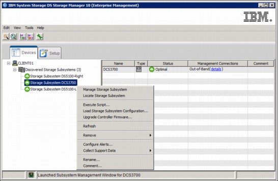
Figure 5-5 Subsystem menu
Manage Storage Subsystem option
This option opens the Subsystem Management window. You can also double-click the system to manage it.
Locate Storage Subsystem option
If you have several storage subsystems that are installed, it can be hard to find the right one. If you select this option, the indicator light on the selected subsystem starts flashing (Figure 5-6).

Figure 5-6 Indicator lights are flashing
Execute Script option
Here you can open the DCS3700 Script Editor. This Editor can be an effective and useful tool to manage your subsystem. For more information about how to use it, see 15.3.1, “Script Editor” on page 465.
Load Storage Subsystem Configuration option
Section 15.8.1, “Sample command: Save configuration script file” on page 478 describes how to save a configuration script file that is based on the current environment. This is done on the CLI by running the save StorageSubsystem configuration command. With the Load Storage Subsystem Configuration option in Storage Manager, you can load a saved file so that the configuration is applied to another storage system
This option appends the uploaded configuration to your storage subsystem unless you do either of the following operations:
•Reset the storage subsystem’s configuration before loading the new one.
•Edit the saved script so that it contains the reset configuration command.
To upload a configuration file, complete the following steps:
1. Select this option and the load configuration notes display. Read them carefully, and then click Yes.
2. The Script Editor opens. Select your configuration file and click OK.
3. The file loads in to the Script Editor and the Confirm Load Configuration window opens:
a. If you want to append a configuration to the existing one, click Execute, and the script appends the uploaded configuration to the existing one.
b. If you want to restore your subsystem’s configuration before the new one is uploaded, select Edit and look in the Script Editor for the lines that are shown in Figure 5-7 and uncomment them. After uncommenting these two lines (shown below), click Tools → Verify → Execute from the menu bar to run the script and upload the
new configuration.
new configuration.
show “Deleting the existing configuration.”;
set storagesubsystem resetConfiguration = true;

Figure 5-7 Uncomment lines to delete the existing configuration before uploading a new one
|
Existing configurations: The script does not overwrite an existing configuration, that is, the script fails if it attempts to build an array by using drives that are already part of an existing array. However, if you have lost an array that had data stored on it, do not reapply the configuration by using this script because it initializes the drives and delete the data. Instead, you should contact IBM technical support to see if your data can be recovered.
Note: To save time, use the load configuration file option for new DCS3700 storage subsystems by using a previously created file for an existing DCS3700. For example, if you have many storage subsystems with similar configurations, you can configure one, save the configuration file, modify it if necessary (for example, to use a separate storage subsystem or define different hosts), then use it to configure quickly the remaining storage subsystems. You could also use this option to re-create replacement DCS3700s if your original hardware was destroyed in a disaster.
|
Upgrade Controller Firmware option
Select this option to upgrade the firmware of the controllers in the storage subsystem. While upgrading the firmware, the firmware file is downloaded from the host to the controller. After downloading the firmware file, you can upgrade the controllers in the storage subsystem to the new firmware immediately. Optionally, you can download the firmware file to the controller and upgrade the firmware at a more convenient time.
The process of upgrading the firmware after downloading the firmware file is known as activation. During activation, the existing firmware file in the memory of the controller is replaced with the new firmware file. The firmware upgrade process requires that the controllers have enough free memory space in which the firmware file can be until it
is activated.
is activated.
The Upgrade Controller Firmware window and the Download Firmware dialog are shown
in Figure 5-8.
in Figure 5-8.

Figure 5-8 Upgrade Controller Firmware window
You also can use the command-line interface (CLI) to download and activate firmware to several storage subsystems. If the Status field shows that the system is not upgradeable, check the Details window for more information about the problem.
For more information about the upgrade procedures, see Chapter 14, “Administration: Upgrade” on page 421.
Refresh option
Select this option to refresh the view of the Enterprise Management window (Figure 5-9). You might use this option if a system’s status has changed, for example, after an error recovery.
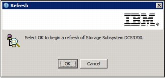
Figure 5-9 Refresh View
Remove option
Here you can remove the selected storage subsystem from your view. This does not affect the views of any other storage management stations. To remove a storage subsystem, select this option and click OK (Figure 5-10).

Figure 5-10 Remove Subsystem
Remove Management Connections window
The Remove Management Connections window is shown in Figure 5-11.

Figure 5-11 Remove Management Connections
Configure Alerts option
The IBM System Storage DCS3700 Manager includes the Event Monitor Service, which enables the host running this monitor to send out alerts through email (SMTP) or traps (SNMP). The Event Monitor can be used to alert you of critical events for any of the DCS3700 storage subsystems in your environment. For high availability, the Event Monitor service should run on two separate host systems that are available 24 hours a day. Both servers should be capable of out-of-band and in-band management. This ensures correct alerting even if one server is down or a connection type has failed.
|
Note: The DCS3700 does not send the email or SNMP trap itself. The management station (running the event monitor service) sends the notification on behalf of the storage server. If the management station is down, no alerts are sent.
|
What systems are monitored
Depending on how you set up alerts, different storage subsystems are monitored by the Event Monitor. Here is how alerts can be configured:
•To configure alerts for all storage systems that are listed in the Enterprise Management window, right-click your local management system in the Enterprise Management window (at the top of the tree) and select Configure Alerts, as shown in Figure 5-12 on page 169.

Figure 5-12 Configure Alerts for all systems
•If you can see the same storage subsystem through separate paths, directly attached, and through different hosts running the host agent, you receive multiple alerts. Right-click a specific storage system to define the alerting specifically for this storage server, as shown in Figure 5-13.

Figure 5-13 Configure Alerts for a particular subsystem
•Select Configure Alerts for one or more systems. The alert window opens (Figure 5-14).
Email alerts
This section describes how to work with email alerts:
1. To send email alerts, you must first define an SMTP server. Enter the name or IP address of your mail server and the sender email address, as shown in Figure 5-14.
.
Figure 5-14 Configure Alerts - define a mail server
2. Select the Filtering tab to configure the events that will trigger an alert, as shown in Figure 5-15.

Figure 5-15 Filtering the event that will trigger the alert
3. Select the email tab to configure the email address to which the alerts are sent. Enter the email addresses and click Add, as shown in Figure 5-16.
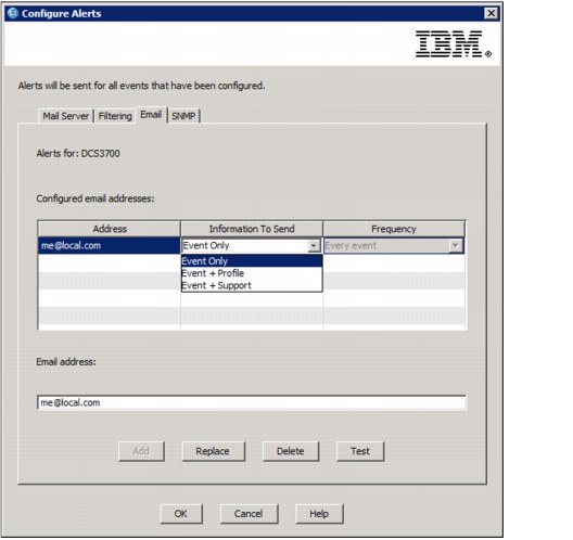
Figure 5-16 Configure Alerts - defining email address
In the drop-down menu next to the address, you can select which information should be sent and how often the data should be delivered. If you highlight an address, you can also send a test email to validate that your configuration is working.
SNMP alerts
Similarly, select the SNMP tab for receiving and handling the traps that are sent by the service. Enter your community name and the destination dress of your SNMP Server and click Add, as shown in Figure 5-17 on page 173.

Figure 5-17 Configure Alerts - SNMP
|
Note: An SNMP manager is required to receive and translate your SNMP traps, for example, IBM Systems Director. For more information about IBM Systems Director and how to configure it, see Implementing IBM Systems Director 6.1, SG24-7694.
|
Collecting support data
The storage management software can automatically save a copy of the support data when the client monitor process detects an event. You can enable or disable the feature. This can be done either automatically if the user want to collect the data or scheduled. Figure 5-18 shows how to enable the automatic collection of support data.

Figure 5-18 Automatic collection of support data
Figure 5-19 shows the window that you use to create/edit the schedule for collecting
support data.
support data.

Figure 5-19 Create/Edit a schedule for collecting support data
After you create the schedule, click OK and check whether the schedules are updated and check whether you get a confirmation (Figure 5-20).
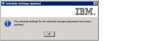
Figure 5-20 Schedule Settings Updated
In the Schedule Support Data Collection window (Figure 5-21), you can verify your settings, and edit, suspend, resume, or remove the schedule.
.
Figure 5-21 Schedule Support Data Collection
The default location for the saved data is C:Program Files (x86)IBM_DSclientdatamonitor. The data is saved in a file starting with the prefix BUNDLE, for example, BUNDLE.Baseline.60080e500023f8f4000000004fffe472.DCS3700.Jul192012. The file names of the saved files include the date. The operation keeps a maximum of five files. If five files already exist, the operation deletes the oldest file before saving a new one. If there is not enough disk space to save a new file, the operation deletes the oldest files until there is enough space. If your enclosure contains drawers, the diagnostic data for that enclosure is archived in a separate compressed file named EnclosureComponentsStateCapture_<user-defined>.zip in the same location that is specified for the Customer Support Bundle. This data is requested in a support case.
The type of data that is collected is described in Table 5-1 on page 177.
Table 5-1 Collected support data
|
Type of data
|
File name and description
|
|
Drive cabling topology
|
Connections.txt: This file contains information about the connections between the drive expansion unit environmental services module (ESM) and the controller pair.
|
|
Drive command aging timeout values
|
driveCommandAgingTimeout.txt: This file contains the default and current values for the command aging timeout field for every drive.
|
|
Features of the storage subsystem
|
featureBundle.txt: A list of the number of logical drives, drives, and drive expansion units that are allowed in the storage subsystem, and a list of the Premium Features that are available and their limits.
|
|
Firmware inventory
|
firmwareinventory.txt: A list of all of the firmware versions for all of the components in the storage subsystem.
|
|
I/O path statistics
|
ioPathStatistics.zip: Contains raw performance data for each controller that can be used to analyze application performance issues.
|
|
iSCSI connections
|
iscsiSessionConnections.txt: A list of all of the current iSCSI sessions.
|
|
iSCSI statistics
|
iscsiStatistics.csv: Statistics for the Ethernet media access control (MAC), Ethernet Transmission Control Protocol (TCP)/Internet Protocol (IP), and iSCSI target.
|
|
Major event log
|
majorEventLog.txt: A detailed list of events that occur on the storage subsystem. The list is stored in reserved areas on the disks in the storage subsystem. The list records configuration events and component failures in the storage subsystem.
|
|
NVSRAM data
|
NVSRAMdata.txt: A controller file that specifies the default settings for
the controllers. |
|
Object bundle
|
objectBundle: A detailed description of the status of your storage subsystem and its components, which was valid at the time that the file was generated.
|
|
Performance statistics
|
performanceStatistics.csv: A file containing the number of read requests, write requests, cache read requests, and cache write requests for each logical drive in the storage subsystem.
|
|
Persistent reservations and registrations
|
persistentReservations.txt: A detailed list of logical drives on the storage subsystem with persistent reservations and registrations.
|
|
Read link status data
|
readLinkStatus.csv: A detailed list of errors that have been detected in the traffic flow between storage subsystems on the Fibre Channel loop. The archive also might include a file of historical read link status data.
|
|
Recovery Guru procedures
|
recoveryGuruProcedures.html: A detailed list of all of the Recovery Guru topics that are issued in response to problems detected on the storage subsystem.
|
|
Recovery profile
|
recoveryProfile.csv: A detailed description of the latest recovery profile record and historical data.
|
|
Switch-on-a-chip statistics
|
socStatistics.csv: A detailed list of all the statistics and error counters that are found in the traffic between controllers and switched FC devices.
|
|
State capture data
|
stateCaptureData.txt: A detailed description of the current state of your storage subsystem.
|
|
Storage subsystem configuration
|
storageSubsystemConfig.cfg: A detailed description of the logical configuration on your storage subsystem.
|
|
Storage subsystem profile
|
storageSubsystemProfile.txt: A description of all of the components and properties of a storage subsystem.
|
|
Trace buffer contents
|
traceBuffers.zip: This file contains the contents of the controllers’ trace buffers that are used to record debug information.
|
|
Enclosure capture data
|
EnclosureComponentsStateCapture_<user-defined>.zip: If your enclosure contains drawers, the diagnostic data is archived in this compressed file. The compressed file contains a separate text file for each enclosure that contains drawers. The compressed file is saved as a separate file outside of the Customer Support Bundle.
|
|
Unreadable sectors
|
unreadableSectors.txt: A detailed list of all of the unreadable sectors that have been logged to the storage subsystem.
|
Rename option
If you have multiple DCS3700 storage subsystems that are installed, give each one a user-specified name for easier identification. To rename a DCS3700, select this option, enter a new name for the subsystem, and click OK, as shown in Figure 5-22.

Figure 5-22 Rename Storage Subsystem
|
Note: Set the name only during the initial setup of the box and do not change it later because some operating systems use the storage subsystem name for identification.
|
Comment option
Here you can add a comment to a disk subsystem in the Enterprise Management window. Select this option, enter your comment, and click OK, as shown in Figure 5-23.
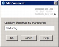
Figure 5-23 Edit comment
Your comment displays in the right pane of the Enterprise Management window, as shown in Figure 5-24. Your comment could be a description of the disk subsystem.

Figure 5-24 Add comment to Storage Subsystem
To delete or edit the comment, re-select the Comment option and modify it as needed. Click OK when done.
5.2.2 The Enterprise Management window menu bar
This section describes the various options in the window menu bar at the top of the Enterprise Management window.
Edit and Tools submenu
All the tasks that are described in 5.2.1, “Subsystem menu” on page 164 can also be accessed from the task menu bar. To do this, highlight a subsystem and open the appropriate menu. The Edit (Figure 5-25) and Tools (Figure 5-26) submenus contain all of the tasks. Performing these tasks is done exactly as described in the previous section.

Figure 5-25 Edit menu

Figure 5-26 Tools menu
The View submenu
Use this menu to start the Enterprise Management window Task Assistant (Figure 5-27) or to customize the view of your enterprise window by selecting one of the sort options. The Task Assistant is described in 5.1.1, “Initial Setup Tasks” on page 160.
Sort the subsystems in the Enterprise Management window
To sort your subsystems, choose one of the following fields from the menu as a sort key:
•By Name
•By Status
•By Management Connection
•By Comment
•Partially Managed Storage Subsystems
|
Note: Partially Managed Storage Subsystems are storage servers where only one IP address (controller) is connected to the management station. You should ensure that you always add both Ethernet connections. Certain maintenance tasks require a connection to both controllers.
|

Figure 5-27 View submenu
5.2.3 The Quick Access icons
Below the menu bar you see the Quick Access icons, which are used to directly activate certain functions of the Enterprise Management window. Click them to activate their associated task.
Automatically discover new storage subsystems icon
The Automatic discovery icon for the new storage subsystems icon is shown in Figure 5-28.
Figure 5-28 Automatically discover new storage systems icon
This icon starts an automatic discovery of new storage subsystems (Figure 5-29) by sending in-band and out-of-band broadcasts. If it finds directly attached storage subsystems or hosts running the DCS3700 Storage Manager agent (with an attached storage subsystem), it adds these storage subsystems to the Enterprise Management window.

Figure 5-29 Automatic Discovery
|
Note: If your subsystem is not discovered automatically by the wizard (for example, because it is in another broadcast domain), you can add it manually as described in “Add Storage Subsystem to view icon” on page 182.
|
Rescan selected host for new storage subsystems icon
The Rescan selected host for new storage subsystems icon is shown in Figure 5-30.
Figure 5-30 Rescan Host icon
If you are using a host that is running an agent to manage your storage subsystems, you can use this icon to rescan only the selected host. To do this task, highlight the host, click this icon, and the Rescan window appears. Click OK and the host scans for newly attached storage devices.
Add Storage Subsystem to view icon
The Add Storage Subsystem to view icon is shown in Figure 5-31.
Figure 5-31 Add Storage Subsystem to view icon
Click this icon to display the Add Storage Subsystem window. Here you can add systems manually to your Enterprise window view. For out-of-band management, you must provide the IP address or host names of the controllers (Figure 5-32). If the storage subsystem has dual controllers, you must provide the IP address of both controllers.

Figure 5-32 Manually add out-of-band system
For in-band management, specify the IP address or host name of the host that is attached to the storage server (Figure 5-33).

Figure 5-33 Manually add in-band system
Remove Storage Subsystem from View icon
The Remove Storage Subsystem from View icon is shown in Figure 5-34.
Figure 5-34 Remove Storage Subsystem from View icon
To remove a storage subsystem from your view, highlight it, click this icon, and click OK to confirm (Figure 5-35). This subsystem is removed only from your view; the views of other management stations are not affected.
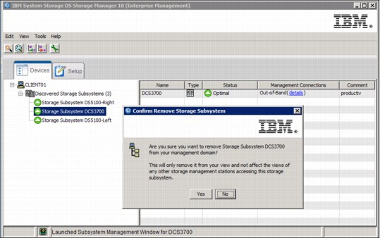
Figure 5-35 Remove Subsystem from view
Launch Management window icon
The Launch Management window icon is shown in Figure 5-36.
Figure 5-36 Launch Management window icon
Highlight a storage subsystem and click this icon to start the Subsystem Management window for the selected system, as described in the window for the selected system.
..................Content has been hidden....................
You can't read the all page of ebook, please click here login for view all page.