


Windows SAS configuration guide for IBM BladeCenter
This chapter describes and explains a sample configuration that shows how to connect logical drives that are configured on an IBM System Storage DCS3700 storage subsystem to a Windows Server 2008 operating system that is running on an IBM BladeCenter HS23 blade server that is connected with SAS Connectivity Modules.
For the Fibre Channel (FC) Windows host attachment guides, see the following documents:
•IBM Midrange System Storage Implementation and Best Practices Guide, SG24-6363
•IBM System Storage DS Storage Manager Version 10 - Installation and Host Support Guide, found at:
16.1 Required equipment
Use the following hardware and software components for this configuration:
•IBM BladeCenter H
•IBM BladeCenter HS23 with Windows Server 2008 installed on a local SAS disk
•IBM BladeCenter Advance Management Module (AMM) installed in a BladeCenter H
•Two IBM BladeCenter SAS Connectivity Modules
•IBM BladeCenter dual port SAS Expansion card (CIOv)
•A DCS3700 storage subsystem
•Two SAS cables
•The latest version of DS Storage Manager running on an external management workstation (at the time of writing, this is Version 10.83)
Figure 16-1 shows our sample hardware setup for BladeCenter and DCS3700 connectivity.

Figure 16-1 Hardware setup - BladeCenter and DCS3700 connectivity
16.2 IBM BladeCenter setup
Check the IBM support website for the latest DCS3700 interoperability matrix to ensure that all the hardware that is used for this configuration is supported. Ensure that the BladeCenter, blade server, and modules are updated with the latest firmware. For the latest firmware, see the following IBM Support websites:
•For Storage Interoperability:
•For BladeCenter Interoperability:
16.2.1 Installing Windows Server 2008 R2
Follow the operating system installation instructions that are available for each IBM BladeCenter blade and IBM System x server. The installation guides can be found in the “Install/use” section of each product’s support websites.
For IBM BladeCenter HS23 (7885) with Microsoft Windows Server 2008 R2 setup, use the instructions that are found at:
16.2.2 HS23 SAS Expansion Cards
You must install the IBM BladeCenter SAS Connectivity Card (CIOv) in the HS23 BladeCenter host before you can proceed with other tasks. Although this is not a difficult task, be sure to consult the user’s guide for the host server and follow the instructions for options installation. The next step is the SAS Expansion Card driver installation.
|
Important: The connectivity modules in I/O module bay 3 and I/O module bay 4 and all expansion cards in the BladeCenter unit must use the same interface type. Therefore, you must install SAS expansion cards before you install connectivity modules in the blade servers in your BladeCenter unit. For more information about the SAS expansion card, see the Installation and User's Guide for the SAS expansion card at one of the following URLs:
Note: The BladeCenter SAS Expansion Card is a dual port card. Port # 1 connects to the SAS Connectivity Module in BladeCenter I/O module bay 3 and port # 2 connects to the SAS Connectivity Module in BladeCenter module bay 4.
|
16.2.3 Recording the SAS Expansion Card WWPN
The following steps demonstrate how to record the SAS Expansion Card WWPN for later use in setting up the host-to-LUN mappings in the DCS3700 storage subsystem:
1. Turn on or restart the HS23 host.
2. Press Ctrl+c to enter the LSI Logic Configuration Utility, as shown in Figure 16-2.

Figure 16-2 SAS Expansion Card - LSI Logic Configuration Utility
3. The menu that is shown in Figure 16-3 opens after you press Ctrl+c.

Figure 16-3 SAS Expansion Card - LSI Logic Configuration Utility menu
4. Press the Enter key to select the SAS adapter that is internally connected to the SAS Connectivity Module in I/O Module bay 3, as shown in Figure 16-4.

Figure 16-4 SAS Expansion Card - LSI Logic Config Utility adapter selected
5. Record the worldwide port name (WWPN) of the first port on the SAS Expansion Card. The WWPN is needed for defining host ports on the DCS3700 storage subsystem. The WWPN can also be retrieved from the SAS Connectivity Module web interface.
The WWPN can also be recorded by clicking Hardware VPD → Blade Bay → Expansion Card ((in our example, the Blade Bay is Blade6). This action opens the BladeCenter Vital Product Data window. Click the Ports tab to record the WWPNs, as shown in Figure 16-5.

Figure 16-5 Expansion Card Unique IDs
6. The name of the SAS adapter for the expansion card is SAS3020XD and is visible in the Adapter List window. To determine whether the SAS adapter is the expansion card, select a SAS adapter and use the View SAS Topology window to display whether the SAS adapter is connected to the internal hard disk drives or to the SAS Connectivity Modules in your BladeCenter chassis, as shown in Figure 16-6.

Figure 16-6 SAS Expansion Card - LSI Logic Config Utility adapter confirmation
16.2.4 HS23 SAS Expansion Card device driver
In this example, we use the SAS Expansion Card device driver that is part of the Windows Server 2008 R2 installation. The SAS Expansion Card is installed and Windows Server 2008 R2 recognizes the hardware and applies the appropriate device driver. At the time of writing, the latest SAS Expansion Card device driver for Windows Server 2008 R2 was available from following IBM website:
16.2.5 SAS Connectivity Modules
Install the IBM BladeCenter SAS Connectivity Modules only in BladeCenter I/O module bay 3 and I/O module bay 4 of the following supported BladeCenter units:
•BladeCenter E Type 8677
•BladeCenter HT Type 8740 / 8750
•BladeCenter H Type 7989/8852
•BladeCenter S Type 7779/8886
Installing a connectivity module in I/O module bay 3 or I/O module bay 4 provides connectivity to the SAS expansion cards installed in the blade servers in your BladeCenter unit. Installing two connectivity modules allows you to have two connections to the SAS expansion cards that are installed in the blade servers.
|
Important: The connectivity modules in I/O module bay 3 and I/O module bay 4 and all expansion cards in the BladeCenter unit must use the same interface type. Therefore, you must install SAS expansion cards before you install connectivity modules in the blade servers in your BladeCenter unit. For more information about the SAS expansion card, see the Installation and User's Guide for the SAS expansion card, found at:
|
Connect the cables from the DCS3700 storage subsystem controllers A and B to the external ports # 1 of the two SAS Connectivity Modules, as shown in Figure 16-1 on page 482.
16.2.6 SAS Connectivity Module firmware update
Ensure that your SAS Connectivity Module is updated with the latest firmware. For the latest firmware update, go to the following website:
To update the connectivity-module firmware to the latest version, complete the
following steps:
following steps:
1. Log on to the SAS Connectivity Module by using the web interface with the IP address that is defined for the connectivity module in the BladeCenter Advance Management Module (AMM), as shown in Figure 16-7. Use USERID as the user ID and PASSW0RD as the password. (0 in PASSW0RD means null). You can change the password under the Administer Users menu option after you are logged on.

Figure 16-7 SAS Connectivity Module - login
2. In the Monitor Module window, click Update Firmware. The Update Firmware window opens, as shown in Figure 16-8. The current firmware level is also displayed.

Figure 16-8 SAS Connectivity Module - Update Firmware
3. In the Firmware File field, enter the new firmware file name, or click Browse and locate the firmware file.
4. Click Install to install the new file. A firmware update progress window opens, as shown in Figure 16-9.

Figure 16-9 SAS Connectivity Module - installation confirmation
5. Avoid any power off or restart actions during the firmware upgrade, as noted in Figure 16-10.

Figure 16-10 Installing firmware
6. Click OK or Cancel. If the installation of the new firmware file is successful, an installation confirmation window opens, as shown in Figure 16-11. If there are errors during the installation, an error message window opens.

Figure 16-11 SAS Connectivity Module - update successful
16.2.7 Configuring the SAS Connectivity Module
Ensure that the external ports on the SAS Connectivity Modules are enabled to allow connectivity from the DCS3700 storage subsystem and I/O traffic to pass through the module.
From the BladeCenter Advance Management Module web interface GUI, click I/O Module Tasks → Admin/Power/Restart and ensure that the external ports for the I/O modules in bays 3 and 4 are enabled, as shown in Figure 16-12.

Figure 16-12 SAS Connectivity Module - configuration
16.2.8 SAS Connectivity Module zoning
Zoning is the partitioning of a Fibre Channel fabric into smaller subsets to restrict interference, add security, and to simplify management. Although a SAN makes available several virtual disks (LUNs), each system that is connected to the SAN should be allowed access only to a controlled subset of the LUNs. For a host (initiator) to gain access to the storage subsystem (target), the initiator HBA WWPN or the switch port to which it is connected must be zoned with the corresponding target WWPN or the switch port, and this zone should be a member of the active zoneset. Thus, although zoning is a tool to permit or deny access to the devices, it does not have the intelligence to apply controls beyond the fabric, that is, to present or hide the LUN to hosts.
Several predefined SAS fabric zone configurations are available from the factory and can be started by a simple selection from the Advanced Management Module (AMM). Zoning on the SAS Connectivity Module can be performed by using the AMM I/O module configuration option, web GUI, SAS, telnet, and SAS Connectivity Module (SCM) application.
Click I/O Module Tasks → Configuration in the BladeCenter AMM GUI web interface window. For I/O Module 3 or I/O Module 4, select Zone Configuration Management. A window opens showing the predefined zone configuration options, as shown in Figure 16-13.

Figure 16-13 SAS Connectivity Module - predefined zones
You can select from five predefined zone configuration options. In this example, the option 5 predefined zone configuration is active (indicated by a check mark), as shown in Figure 16-13. With this option, each server bay is exclusively zoned with all the external ports, thus allowing access to one or more storage controller ports that are connected to the SAS Connectivity Module.
The example in Figure 16-14 on page 495 was captured from the SAS Connectivity Module web interface. It lists the Basic Zone Permission table for the HS23 blade server in slot 6 because the blade in slot 6 is used for this example. The blade in slot 6 is zoned with four external ports. The External port is set to True under the Connected column and Normal under the Status column. This is because the DCS3700 storage subsystem Controller A port is connected to the external port #6 for this example.
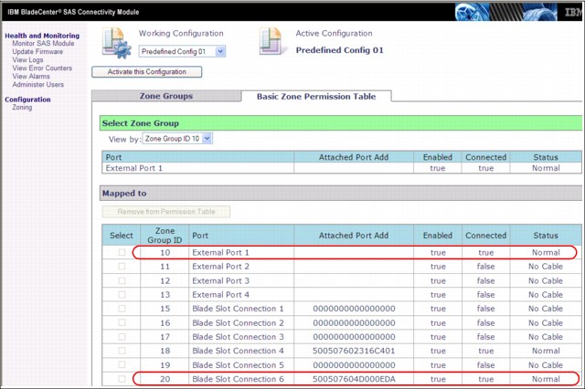
Figure 16-14 SAS Connectivity Module - zone configuration
|
Note: There is only a single path active from the DCS3700 storage subsystem controller A to the SAS Connectivity Module in BladeCenter I/O slot bay 3. The second path from DCS3700 storage subsystem controller B is to the SAS Connectivity Module in BladeCenter I/O slot bay 4.
|
16.3 Installing the DS Storage Manager host software
Here you install the host server components of DCS3700 Storage Manager. These components include the following items:
•DS Storage Manager 10 Utilities
•DS Storage Manager 10 Agent
•MPIO Device Specific Module (DSM)
You install DS Storage Manager 10 Utilities because then you can run the hot_add utility; if you use this utility, you do not need to reboot the host server when you add logical drives.
Because the host server contains a 2-port SAS Expansion Card, you need multipath support. This support is installed as part of the Host selection when you install the DS Storage Manager. For the exact installation steps, see Chapter 4, “IBM System Storage DS Storage Manager installation” on page 131.
After the DCS3700 Storage Manager client is installed, add the DCS3700 storage subsystem in the Enterprise Management window and prepare the logical drives for the Windows server. For simplicity’s sake, create just one logical drive of 20 GB.
Define your Windows Server 2008 host in the Storage Manager and map it to the
logical drive.
logical drive.
We explained how to add storage subsystems, define hosts, prepare logical drives, and map them in Chapter 10, “Administration: Mappings tab” on page 327, so we do not repeat these steps here. Figure 16-15 shows the 200 GB logical drive named Data that is mapped to the host server Blade06.

Figure 16-15 Drive mapping
16.4 Configuring the disk space in Windows Server 2008 R2
The logical drive must be recognized in Windows before you can start using the disk space. One possibility is to shut down and reboot the host server or to select Rescan Disks from the Action menu bar of the Disk Management window. A better alternative is to use the hot_add utility (a part of SMutil).
By default, the hot_add executable file is in C:Program Files (x86)IBM_DSutil. In a command prompt window, change to this directory. If you installed the DCS3700 Storage Manager in a non-default directory, change to that directory instead, and then to subdirectory util. Then, run hot_add.
When the utility completes, you can use the Disk Management applet in the Computer Management utility and configure the disk space for operating system use. Complete the following steps:
1. Initialize and optionally convert to dynamic disk.
This task is done by using the Initialize and Convert Disk wizard. When the wizard finishes, the Disk Management applet looks similar to Figure 16-16.
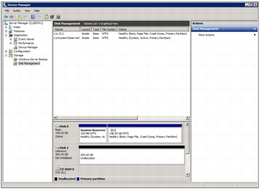
Figure 16-16 Disk Management applet - initialized disk
As you can see, the 200 GB logical drive is recognized as Disk 1, but it does not contain a partition yet. (It is deallocated.)
2. Initialize the disk by right-clicking Disk1 and selecting Initialize Disk, as shown in Figure 16-17.

Figure 16-17 Initialize Disk
3. Create and format a partition. Right-click in the deallocated disk space and select New Simple Volume, as shown in Figure 16-18.
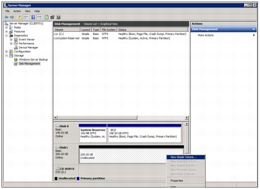
Figure 16-18 Creating a partition
The New Simple Volume wizard starts.
4. Follow procedure that is presented by the wizard to define the partition size, drive letter, file system, and volume label. The partition is created and formatted. The Disk Management applet now displays the new partition (allocated drive F) that is ready to be used (see Figure 16-19).

Figure 16-19 New partition on the logical drive
5. You can now access the logical drive on the DCS3700 storage subsystem as drive letter F, as shown in Figure 16-20.

Figure 16-20 Logical drive is ready for use
..................Content has been hidden....................
You can't read the all page of ebook, please click here login for view all page.