


Hardware Management Console overview
This chapter provides an overview of the Hardware Management Console (HMC) and the HMC V8 enhancements through Release 8.4.0.
This chapter describes the following topics:
1.1 Overview of Hardware Management Console (HMC)
The HMC is an appliance for planning, deploying, and managing IBM Power Systems servers. It can be used to create and modify logical partitions, including dynamically adding and removing resources from a running partition. This section briefly describes some of the concepts and functions of the HMC and introduces the user interface that is used for accessing those functions.
1.1.1 Introduction to the Hardware Management Console
The HMC allows you to configure and manage servers. One HMC can manage multiple servers, and dual HMCs can provide redundant support by managing the same system. To ensure consistent function, each HMC is preinstalled with the HMC Licensed Machine Code.
|
Note: Virtualization is not supported on the IBM Power System S824L (8247-42L) server.
|
To provide flexibility and availability, you can implement HMCs in several configurations.
Local HMC
A local HMC is an HMC that is physically located close to the system it manages and is connected by either a private or public network. An HMC in a private network is a DHCP server for the service processors of the systems it manages. An HMC may also manage a system over an open network, where the managed system’s service processor IP address has been assigned manually using the Advanced System Management Interface (ASMI).
Physical proximity
Prior to HMC version 7, at least one local HMC was required to be physically located near the managed systems. This is not a requirement with the Version 7 and the HMC’s web browser interface.
Remote HMC
A remote HMC is an HMC that is not physically located near its managed systems. This could be in another part of the same room or data center, in another building, or even on another site. Typically, a remote HMC is attached to its managed servers using a public network, but configurations with a remote HMC attached to a private network are also possible. Prior to HMC version 7, at least one local HMC was required. With Version 8, any or all HMCs may be virtual HMC (vHMC).
Redundant HMC
The HMC allows you to configure and manage servers. One HMC can manage multiple servers, and dual HMCs can provide redundant support by managing the same system. To help ensure consistent function, each HMC is preinstalled with the Hardware Management Console Licensed Machine Code.
The IBM Power Systems HMC virtual appliance can be used to manage any of the systems that are supported by the Version 8 HMC, which includes Power Systems servers with IBM POWER6®, POWER7®, and POWER8® processors.
The Power Systems vHMC offers these benefits:
•Provides hardware, service, and basic virtualization management for your Power Systems servers.
•Offers the same functionality as the traditional HMC.
•Runs as a virtual machine on an x86 server virtualized either by VMware ESXi or Red Hat KVM.
When the server is connected to the higher version of the management console, the partition configuration is upgraded to the latest version. After the partition configuration upgrade, lower levels of the management consoles will not be able to interpret the data correctly.
After the server is managed by the higher version of the management console, you must first initialize the server before you can go back to the lower version of the management console. You can restore a backup that is taken at the older level or re-create the partitions.
If the server is not initialized, one of the following outcomes can occur depending on the version of the lower-level HMC:
•HMC Version 8 Release 8.4.0 and later reports a connection error of Version mismatch with reference code Save Area Version Mismatch.
•HMC Version 8 Release 8.3.0 and earlier might report a server state of Incomplete or Recovery. In addition, partition configuration corruption can also occur.
Predefined user IDs and passwords
Predefined user IDs and passwords are included with the HMC. An imperative step to your system’s security is that you change the hscroot predefined password immediately. The user IDs and passwords are case-sensitive.
Table 1-1 shows predefined user IDs and passwords that are included with the HMC.
Table 1-1 Predefined HMC user IDs and passwords
|
User ID
|
Password
|
Purpose
|
|
hscroot
|
abc123
|
The hscroot user ID and password are used to log in to the HMC for the first time.
|
|
root
|
passw0rd
|
The root user ID and password are used by the service provider to perform maintenance procedures. They cannot be used to log in to the HMC.
|
1.1.2 What’s new in Managing the HMC through the HMC Enhanced+ interface
Read about new or significantly changed information in the topic “What’s new in Managing the HMC through the HMC Enhanced+ interface” since the previous update of the topic collection described in this section:
October 2015
This update added the following topics:
•SR-IOV Firmware Update
•Test Network Connectivity
•View Network Topology
•Update the Hardware Management Console
•OS and VIOS Images
•Adding, Copying, or Modifying User Profiles
•Updated the Templates and OS Images topic
June 2015
This update added the following topics:
•The procedures and functions of the HMC Enhanced + Tech Preview (Pre-GA) interface, which was an option that was provided with HMC Version 8.2.0, are the same as the HMC Enhanced+ interface that is provided with HMC Version 8.3.0. Only the HMC Enhanced+ is referred to in the documentation, but that content also applies to the HMC Enhanced + Tech Preview (Pre-GA) interface.
•The functions of the HMC Enhanced interface, which was an option that was provided with HMC Version 8.1.0, or later, are now available as a part of the HMC Enhanced+ interface that is provided with HMC Version 8.3.0.
•Added the User Properties and Session handling topics.
•Updated the Power Management topic.
November 2014
This update added the following topic:
•Added information about the HMC Enhanced + Tech Preview (Pre-GA) interface for HMC Version 8, Release 2, or later on IBM Power Systems servers that contain the POWER8 processor.
1.1.3 Functionality improvements
The following new and improved functions are made available:
•Improved virtualization user experience starting with HMC V8.2.0.
•Enhanced and simplified HMC management of PowerVM virtualization enables automation and helps simplify the setup and operation of PowerVM.
•Improved no-touch Virtual I/O Server (VIOS) virtualization management enables complete virtualization administration from HMC.
•Delivers one-touch VIOS deployment that enables VIOS images to be deployed from HMC to help simplify the setup of I/O virtualization and PowerVM.
•Has system and partition templates that enable site-specific virtual machine configurations to be consistently deployed and can be used to enforce virtualization best practices for various configurations.
•Includes simplified Remote Restart, removing need for storage area network (SAN/LUNs).
•Contains operating system-level shutdown for IBM i partitions, providing parity with existing support for VIOS, IBM AIX and Linux.
•Has technology preview of the concurrent activation and network install graphical user interface for partition operating system.
•Has technology preview for new User Interface capabilities such as quick search, gallery views, graphical topology, and improved resource views.
•Delivers enhanced manual and automatic First Failure Data Capture (FFDC) on Live Partition Mobility (LPM) abort.
•Includes, with HMC V8.2, IBM POWER8 Enterprise hardware support.
|
Note: The virtualization improvements implemented by the HMC require HMC V8.2. This function is already available in HMC V8.10 SP1.
|
PowerKVM V2.1.1 contains additional support for new Linux distributions, additional I/O support, and availability improvements.
Enhancements
Major enhancements include the following items:
•Peripheral Component Interconnect (PCI) pass-through I/O support allows more options for performance.
•Mixed Endian virtual machine support on a single PowerKVM host provides increased flexibility.
•PCI hot plug support provides expanded availability by allowing new devices to be added dynamically.
•Support for SUSE Linux Enterprise Server 12 and Ubuntu 14.10 provides a larger choice of Linux versions.
Hardware
Hardware support was enhanced with the following items:
•x86 64-bit hardware with hardware virtualization assists (Intel VT-x or AMD-V).
•Resources for the HMC virtual appliance VM: four CPUs, eight GB of memory, 160 GB of disk space, and two network interfaces.
•IBM Power Systems HMC virtual appliance is included as part of all Pure Power Primary Manager Node Indicator 8374-01M feature EHKZ orders.
Software
Software support includes the following item:
•Virtualization: Either VMware ESXi V5 or Red Hat Enterprise Linux 6.x with KVM
Unsupported functions
The following items are not supported by the HMC:
•Format media
•Call Home with a modem
•Call Home of HMC hardware failures
|
Note: HMC Version 8 no longer supports POWER5.
|
New vHMC functions
The vHMC introduces the following functions:
•Activation engine, which provides configuration on the first boot
•Accept license, locale, network (DHCP not supported), Secure Shell (SSH), and Network Time Protocol (NTP)
•Allow second virtual disk multiple for /data
The HMC virtual appliance has several differences from the hardware appliance HMC:
•An activation engine allows unique configuration during initial deployment. Differences exist in the way the license acceptance dialog is presented. Support exists for multiple virtual disks for additional data storage. Format of physical media is not supported, but this is supported through a virtual device attached to the virtual machine (VM).
•Since the hardware and server virtualization is supplied by the client to run the HMC virtual appliance, this infrastructure that actually hosts the HMC virtual appliance is not monitored by IBM. The HMC virtual appliance does continue to monitor the Power Systems hardware just like the HMC hardware appliance. Both HMC form factors provide remote notification of system errors for the managed Power Systems servers.
•Any software maintenance that is required for the HMC virtual appliance is done using the same procedure as is currently performed using fix central with the hardware-based HMC. Further information about the HMC maintenance strategy is at the following web page:
1.1.4 Major functions of the Hardware Management Console
With the HMC, a system administrator can do logical partitioning functions, service functions, and various system management functions by using either the web-browser-based user interface or the command-line interface (CLI). The HMC uses its connection to one or more systems (referred to in this book as managed systems) to do various functions:
•Creating and maintaining logical partitions in a managed system
The HMC controls logical partitions in managed systems. These tasks are explained in 5.6, “Partition management” on page 370.
•Displaying managed system resources and status
These tasks are explained in 5.5, “Systems Management for Servers” on page 340.
•Opening a virtual terminal for each partition
The HMC provides virtual terminal emulation for AIX and Linux logical partitions and virtual 5250 console emulation for IBM i logical partitions.
•Displaying virtual operator panel values for each partition
You can see the operator panel messages for all partitions within managed systems in HMC.
•Powering the managed systems on and off
These tasks are explained in Chapter 5, “Operating” on page 291.
•Performing dynamic logical partition (DLPAR) operation
With the HMC, you can do DLPAR operations that change the resource allocation (such as processor, memory, physical I/O, and virtual I/O) dynamically for the specified partition. These tasks are explained in 5.7, “Dynamic partitioning” on page 376.
•Managing Capacity on Demand operation
These tasks are explained in 5.11, “Capacity on Demand (CoD)” on page 405.
•Managing virtualization features
These tasks are explained in “PowerVM” on page 365.
•Managing platform firmware installation and upgrade
These tasks are explained in 6.9.6, “Managed system firmware updates” on page 467.
•Acting as a service focal point
You can use the HMC as a service focal point for service representatives to determine an appropriate service strategy and to enable the service agent to call home to IBM. These tasks are explained in 6.3, “Serviceability” on page 425.
HMC Version 8 uses a web-browser-based user interface. This interface uses a tree-style navigation model that provides hierarchical views of system resources and tasks by using drill-down and launch-in-context techniques to enable direct access to hardware resources and task management capabilities. This version provides views of system resources and provides tasks for system administration. For more information about using the web-browser-based user interface, see 5.1.1, “Web-based user interface” on page 292.
1.2 Enhancements in HMC Version 8
This section gives an overview of the new content that can be exercised on this HMC code level:
•An enhancement was added in HMC to provide support for VLAN tag for network boot of IBM i.
•HMC provides complete management of the shared storage pool cluster functionality with the multiple tier and pool mirroring support. Additional features of migrating the shared storage pool volumes across tiers, and resizing the shared storage pool volumes is supported in the HMC V8R8.4.0.
•Added SFTP protocol support to Power firmware update.
•Added update support for SR-IOV devices.
•Migration with Inactive Source Storage VIOS. With this feature, you can migrate logical partitions even if one of the Virtual I/O Servers in a redundant setup is not active. Virtual storage adapter information (virtual SCSI and virtual Fibre Channel) is persisted for all the partitions on each (managing) HMC that is used during migration. A server-level preference (allow_inactive_source_storage_vios) is provided to enable this feature.
•Convert Permanent Capacity on Demand Entitlement to Mobile. In the HMC V8 release, a new function is provided that allows the IBM Product Fulfillment to provide a Capacity on Demand configuration file that converts permanent Capacity on Demand entitlements to mobile entitlements so that they can be used by a Power Enterprise Pool.
•Improvement to communication between management console and VIOS to make Live Partition Mobility operation resilient to network disruption and heavy load.
1.2.1 Further enhancements to Enhanced+ user interface
The Enhanced+ User Interface received the following major enhancements:
•Consolidation of Templates and OS Images under one window.
•Addition of Action buttons to tables improves touch-screen accessibility.
•Improvements to New System Experience. Newly added systems will be placed at the top of the table or beginning of the gallery view until the view is refreshed, making them easily accessible for faster configuration.
•Improvements to the integrated HMC help:
– You can now open the help in a pop-out window to view help content and HMC User Interface at the same time.
– Search functionality is integrated into a new help pop-out window.
– The help window now shows a table of contents, previously viewed topics, and also related topics.
•Consolidation of System Properties and Licensed Capabilities. System properties are no longer split between Enhanced+ “look-and-feel” and a separately launched legacy panel. Licensed capabilities are all accounted for under a new PowerVM task.
1.2.2 Virtual storage diagrams
The following virtual storage diagrams are available:
•Partition-level storage diagram. Accessible from the logical partition in the Enhanced+ user interface only, this feature provides a visual representation of the storage tied to the individual partition. Easily illustrates the relationships between different storage entities such as shared storage pools, disks, and adapters.
•System-level storage diagram. Accessible from the managed system in the Enhanced+ user interface only, this feature provides a visual representation of the high-level storage configuration for an individual system.
The HMC can work with the integrated management module 2 (IMM2) remote control feature on an as-is basis. This feature is useful for installation and upgrades in a lights-out data centers and remote debugging. The IMM2 remote control feature needs to be enabled for this enhancement.
1.2.3 NIST support for HMC
Starting with HMC V8.4.0, the HMC supports NIST SP800-131A by implementing the following features:
•Upgrading JVM to a version that contains NIST support.
•Enabling TLS V1.2; prepare to disable protocols less than TLS V1.2.
•Cryptographic keys adhere to a minimum key strength of 112 bits.
•Digital signatures at a minimum use SHA-256.
•Uses approved random number generator (Java only).
Enabling NIST SP800-131A in HMC enables the following tasks:
•Changes the SSL protocol to TLS V1.2.
•HMC now uses the SP 800-131a approved cipher suites.
HMC browser requirements for NIST
Table 1-2 lists the HMC browser requirements after NIST SP800-131A is enabled.
Table 1-2 HMC browser requirements
|
Browser name
|
Browser version
|
NIST (TLS v1.2) supported
|
|
Firefox
|
•1 - 18
•ESR 10 and 17
•19 - 23
|
No
|
|
•24 - 26
•ESR 24‘
|
Yes, but disabled by default
|
|
|
•27+
•ESR31 and later
|
Yes
|
|
|
Internet Explorer
|
6 and 7
|
No
|
|
8 and later
|
Yes, but disabled by default
|
|
|
11
|
Yes
|
|
|
Chrome
|
0 - 29
|
No
|
|
30 and later
|
Yes
|
Checking the HMC security mode
To check the current security mode, run lshmc. If NIST SP800-131A is disabled, the system returns legacy as the output, as shown in Example 1-1.
Example 1-1 HMC without NIST SP800-131A security compliance
hscroot@hmc8:~>lshmc -r -Fsecurity
legacy
If NIST SP800-131A is enabled, the system returns nist_sp800_131a as the output, as shown in Example 1-2.
Example 1-2 HMC with NIST SP800-131A security compliance
hscroot@hmc8:~>lshmc -r -Fsecurity
nist_sp800_131a
Enabling the NIST SP800-131A security mode
To enable the NIST SP800-131A security mode, run chhmc, as shown in Example 1-3.
Example 1-3 Enable the NIST SP800-131A security mode
hscroot@hmc8:~>chhmc -c security -s modify --mode nist_sp800_131a
The Hardware Management Console will automatically be restarted after the security mode is changed. Are you sure you want to change the security mode now (0 = no, 1 = yes)?
1
Broadcast message from root@hmc8 (Thu May 8 14:40:43 2014):
The system is shutting down for reboot now.
|
Note: The HMC is rebooted to enable the new security mode.
|
Disabling the NIST SP800-131A security mode
To disable the NIST SP800-131A security mode, run chhmc, as shown in Example 1-4.
Example 1-4 Disable the NIST SP800-131A security mode
hscroot@hmc8:~>chhmc -c security -s modify --mode legacy
The Hardware Management Console will automatically be restarted after the security mode is changed. Are you sure you want to change the security mode now (0 = no, 1 = yes)?
1
Broadcast message from root@hmc8 (Thu May 8 14:53:33 2014):
The system is shutting down for reboot now.
Effect of NIST SP800-131A compliance
After NIST SP800-131A is activated, the following tasks are effected:
•All base HMC and Hardware Management Console Representational State Transfer (REST) application program interfaces (APIs) calls allow the TLS V1.2 protocol and approved cipher suite.
•If a dependent component is not configured with the TLS V1.2 protocol or an approved cipher suite, the system generates an SSL handshake error.
1.2.4 HMC Virtual Appliance
The IBM Power Systems HMC virtual appliance can be used to manage any of the systems that are supported by the HMC Version 8, which includes Power Systems servers with IBM POWER6, POWER7, and POWER8 processors.
The Power Systems HMC virtual appliance offers these benefits:
•Provides hardware, service, and basic virtualization management for your Power Systems servers
•Offers the same functionality as the traditional HMC
•Runs as a virtual machine on an x86 server virtualized either by VMware ESXi or Red Hat KVM
With the HMC virtual appliance, a new option gives clients additional flexibility to deploy an HMC to manage IBM Power Systems servers. Clients can use the option to provide the hardware and server virtualization to host the IBM supplied HMC virtual appliance.
Power virtualization allows organizations to deliver services more efficiently by consolidating workloads onto fewer servers. This consolidation optimizes utilization of server and storage resources. Power virtualization offerings include IBM PowerVM and IBM PowerKVM. The management of PowerVM typically requires the IBM HMC.
Power virtualization enhancements include the following improvements for PowerVM, PowerKVM, and HMC:
•PowerVM support for Power Enterprise Systems featuring the IBM POWER8 processor.
•An additional option for one-year software maintenance for PowerVM for IBM PowerLinux™ Edition.
•Starting with HMC V8.2.0, which offers an improved user experience for PowerVM.
•Starting with PowerKVM V2.1.1, which provides support for new Linux distributions, additional I/O support, and availability improvements.
Starting with IBM HMC V8 R8.2.0 enhancements improve the usability of IBM PowerVM and support the new Power Enterprise Systems.
1.2.5 PowerVC NovaLink overview
NovaLink is a new virtualization management paradigm for PowerVM systems and allows for dramatic scale improvements for PowerVM based PowerVC environments. For more information about NovaLink and its benefits, see IBM developerWorks®:
Leveraging the NovaLink architecture, PowerVC is able to significantly increase its scaling for PowerVM based systems. In an existing HMC managed environment, PowerVC can manage up to 30 hosts and up to 3000 virtual machines. In a NovaLink based environment, PowerVC can manage up to 200 hosts and 5000 virtual machines. Do not worry though, you can use PowerVC to manage your new NovaLink systems while still managing your HMC managed systems.
PowerVC NovaLink architecture
IBM PowerVC V1.3.0 is an advanced virtualization management offering for Power Systems servers based on OpenStack technology. This comprehensive virtualization management offering is simple to install and use, and enables virtual machine setup and management.
PowerVC can help achieve the following goals:
•Improve resource usage to reduce capital expense and power consumption.
•Increase agility and execution to quickly respond to changing business requirements.
•Increase IT productivity and responsiveness.
•Simplify Power Systems virtualization management.
•Accelerate repeatable, error-free virtualization deployments.
PowerVC can manage AIX, Linux, and IBM i VMs running under PowerVM virtualization and Linux VMs running under PowerKVM virtualization. This release supports the enterprise Power Systems servers that are built on POWER8 technology.
PowerVC includes the following features and benefits:
•Virtual machine image capture, deployment, resizing, and management
•Policy-based VM placement to help improve usage and reduce complexity
•Policy-based workload optimization using either VM migration or resource movement using mobile capacity on demand
•VM Mobility with placement policies to help reduce the burden on IT staff in a simplified GUI
•A management system that manages existing virtualization deployments
•Integrated management of storage, network, and compute resources, which simplifies administration
PowerVC v1.3.0 is built with OpenStack technology, one of the key components of the set of “host” processes, such as nova-compute, neutron (networking), and ceilometer (statistics). Each host that is managed by PowerVC runs an independent set of these processes. Figure 1-1 shows how PowerVC manages PowerVM Systems through the HMC. The HMC acts as a central management controller for sets of hardware. Because the HMC is a closed appliance, PowerVC must run the various compute processes on the PowerVC system directly. This increases the CPU and memory requirements on the PowerVC system, and limits scalability.

Figure 1-1 PowerVC NovaLink architecture
Another limitation is that when PowerVC manages through an HMC, it can manage only up to 500 virtual machines (logical partitions) per HMC. An HMC that is not in use by PowerVC can scale higher, but due to monitoring and other ongoing processes it is tuned for 500 VMs when managed using PowerVC. That means if you want to take advantage of PowerVC at a higher scale, you need multiple HMCs.
The NovaLink architecture changes the virtualization management point for PowerVC. With NovaLink, a thin “management” virtual machine exists on the system. You can see the thin NovaLink partition denoted in Figure 1-2 as NVL.

Figure 1-2 NovaLink partition
This figure shows that the architecture between PowerVC and a PowerVM system is dramatically simplified. The compute processes now run directly on the NovaLink thin virtual machine. This allows PowerVC to dramatically scale out the number of hosts that it can manage using this one-to-one link. It also reduces the load on an administrator’s HMC, allowing the hosts to connect significantly more systems to a given HMC than they would otherwise.
Also, the NovaLink code is tuned directly for PowerVC and OpenStack use. This increased efficiency allows PowerVC to scale a single system to 1,000 virtual machines, double the current 500 VMs per system limitation that exists today. More important, it is aligned with the capabilities of the PowerVM platform itself.
PowerVC NovaLink user experience
The integration of Novalink is designed to provide a unified PowerVM experience. Whether you choose to have PowerVC manage through NovaLink (to take advantage of the scale and speed) or using the traditional HMC path, PowerVC provides you with a consistent experience.
As shown, the experience within the interface is similar. In Figure 1-3, the home page looks identical, although PowerVC is managing NovaLink systems. However, note the dramatic increase in hosts.

Figure 1-3 PowerVC Standard edition interface
There are some areas where changes are evident in the user interface. The most obvious one is the Host Registration panel. Although host registration for an HMC managed system remains unchanged, there is a new path for NovaLink host registration. Administrators provide the IP Address and credentials of the NovaLink VM, which PowerVC uses to register the system. This panel is similar to the panel used for PowerKVM system registration. Figure 1-4 shows the Host Registration panel.

Figure 1-4 Host Registration panel
Beyond this, few other differences exist. The Host panel does not show through which HMC the PowerVC is managing (because it manages through NovaLink).
In addition, to ensure a unified experience, a single PowerVC can mix the management types. This means that a single PowerVC can manage some systems through an HMC and others through NovaLink.
Figure 1-5 shows the NovaLink diagrams.

Figure 1-5 NovaLink diagrams
As shown, the same HMC can be used for PowerVC traditional management, or NovaLink management. However, if a system has NovaLink installed, PowerVC must be pointed to the NovaLink on the system. This mixed mode provides a good path for our existing customers that want to start taking advantage of NovaLink without too much disruption.
Key prerequisites
For IBM PowerVC, the key prerequisites are as follows:
•IBM PowerVM Standard Edition (5765-PVS) for basic functions, and IBM PowerVM Enterprise Edition (5765-PVE) or IBM PowerVM PowerLinux Edition (5765-PVL) for full function.
•IBM PowerKVM (5765-KVM).
•Firmware v8.2, or higher, is required for the new Remote Restart function for IBM PowerVM that is managed by IBM PowerVC.
For IBM PowerVM, the key prerequisites are as follows:
•Any IBM system that includes an IBM POWER7, POWER7+™, or POWER8 processor.
•PowerVM NovaLink requires systems with a POWER8 processor and Firmware 840, or later, that is not managed by an HMC.
NovaLink provides significant advantages for PowerVM users who want to scale up their environments. It is highly concurrent and highly scalable, and can reduce infrastructure complexity. At the same time, the existing PowerVC experience is preserved enabling administrators to take advantage of these benefits quickly.
1.2.6 Live Partition Mobility improvements in PowerVM 2.2.4
PowerVM Version 2.2.4 is a major upgrade that includes many new enhancements. One of the major areas of focus has been improvements to Live Partition Mobility (LPM). Live Partition Mobility is at the heart of any cloud solution and provides higher availability for planned outages.
Better NPIV storage validation
PowerVM Version 2.2.4 allows you to select the level of N_Port ID Virtualization (NPIV) storage validation that best fits your environment. By default, the VIOS at PowerVM Version 2.2.4 will continue to do LPM validation at the NPIV port level. This is appropriate if you are confident that the Storage Area Network (SAN) storage is correctly zoned. If you are setting up a new LPM environment or want to assure yourself that SAN zoning errors are caught prior to starting an LPM operation, you will want to enable the new disk plus port level validation. With disk-level validation enabled, the VIOS will validate that individual disk Logical Unit Number (LUNs) assigned to the partition are usable on the target system. This additional checking will increase the amount of time required to perform LPM validation but has the advantage of surfacing zoning issues that could impact VM migration.
To take advantage of NPIV validation at the disk level, both the source and target VIOS partitions must be at version 2.2.4. To enable disk level validation, the src_lun_val attribute in the LPM pseudo-device (vioslpm0) of the VIOS that is hosting the NPIV storage on the source system must be set to a value of on and the dest_lun_val attribute on the VIOS partitions that are hosting NPIV storage on the destination system cannot be set to lpm_off or off. You can find more information about displaying and changing the VIOS NPIV partition migration attributes at the IBM Knowledge Center (NPIV LUN or disk level validation).
Improved performance
Performance of Live Partition Mobility has been a focus area for IBM over the past few releases of PowerVM. This trend has continued in version 2.2.4 with scalability improvements to support higher speed connections. Prior to version 2.2.4, a single LPM operation was only able to saturate a 10 Gb network connection. To support network bandwidth up to 35 Gb, improvements were made in the VIOS and PowerVM hypervisor in version 2.2.4. The connection can be a single connection or redundant connection built using link aggregation. These faster speed connections for a single LPM operation both reduce the time to migrate a partition and can also address application issues that are triggered by slow speed lines.
To drive a high-speed line at its rated speed, you must allocate additional VIOS resources to the LPM operation. You can control the number of resources using the concurrency level setting for the VIOS and the migrlpar HMC command. The concurrency level can be set specifically for a migration by the migrlpar HMC command and will override the VIOS default for that migration. The highest level of concurrency (best performance and highest amount of resource consumption) is concurrency level 1. This is preferred if you want to drive LPM operation at network speeds greater than 30 Gb. Concurrency level 4 is the default value and is preferred for line speeds up to 10 Gb.
To take advantage of these performance improvements, both the source and target systems must be at PowerVM version 2.2.4. You can find more information about displaying and changing the VIOS concurrency level attributes at the IBM Knowledge Center.
Virtual switch
Starting in PowerVM 2.2.4 the HMC allows the selection of the virtual switch name on the target system. Prior to PowerVM 2.2.4, there was no option to override the virtual switch name so you were required to have the same named virtual switch on both the source and target system.
Minimum PowerVM levels
To support the capabilities discussed in this section, you will need PowerVM 2.2.4 which consists of these releases:
•VIOS Version 2.2.4
•System Firmware Release 8.4.0
•HMC Release 8 Version 8.4.0
For more details, see IBM developerWorks and the IBM Knowledge Center:
1.2.7 IBM i virtual terminal changes
IBM i Access Client Solutions replaces IBM i Access for Linux Emulation. It provides a Java based, platform-independent interface that runs on operating systems that support Java, including Linux, Mac, and Windows.
IBM i Access Client Solutions consolidates the most commonly used tasks for managing your IBM i into one simplified location.
The main IBM i Access Client Solutions window is shown Figure 1-6.

Figure 1-6 IBM i Access Client Solutions
For more information, see the IBM POWER8 systems information at these web pages:
1.2.8 Single root I/O virtualization support
Single root I/O virtualization (SR-IOV) is a PCI standard architecture that enables a PCI Express (PCIe) adapter to become self-virtualizing. It enables adapter consolidation, through sharing, much like logical partitioning enables server consolidation. With an adapter capable of SR-IOV, you can assign virtual slices of a single physical adapter to multiple partitions through logical ports; all of this is done without the need for a VIOS.
Initial SR-IOV deployment supports up to 48 logical ports per adapter, depending on the adapter. You can provide additional fan-out for more partitions by assigning a logical port to a VIOS, and then using that logical port as the physical device for a Shared Ethernet Adapter (SEA). VIOS clients can then use that SEA through a traditional virtual Ethernet configuration. Overall, SR-IOV provides integrated virtualization without VIOS and with greater server efficiency as more of the virtualization work is done in the hardware and less in the software.
Initial support for SR-IOV was included in HMC V7.7.9.0. Starting with the release of HMC V8.8.1.0, support for the following adapters is included:
•PCIe2 4-port (10 Gb FCoE and 1 GbE) SR&RJ45 Adapter
•PCIe2 4-port (10 Gb FCoE and 1 GbE) SFP+Copper and RJ4 Adapter
•Integrated Multifunction Card with 10 GbE RJ45 and Copper Twinax
•Integrated Multifunction Card with 10 GbE RJ45 and SR Optical
For more details about SR-IOV, see the following sources of information:
•IBM Power Systems SR-IOV: Technical Overview and Introduction, REDP-5065
•The “Single root I/O virtualization” topic in the IBM Knowledge Center:
1.2.9 vNIC: Introducing PowerVM Virtual Networking Technology
Virtual Network Interface Controller (vNIC) is a new PowerVM virtual networking technology that delivers enterprise capabilities and simplifies network management. It is a high performance, efficient technology that when combined with SR-IOV NIC provides bandwidth control quality of service (QoS) capabilities at the virtual NIC level. vNIC significantly reduces virtualization overhead resulting in lower latencies and less server resources (CPU, memory) required for network virtualization.
Figure 1-7 shows the vNIC backed by SR-IOV adapter.

Figure 1-7 vNIC backed by SR-IOV adapter
Until now, PowerVM network virtualization has mostly relied on Shared Ethernet Adapter (SEA) in VIOS and virtual switch in the PowerVM Hypervisor to bridge the Virtual Ethernet Adapters (VEA) with the physical network infrastructure. While this approach provides great flexibility in enabling network connectivity for client logical partitions, the SEA-based virtual networking solution incurs layered software overhead and multiple data copies from the time a packet is committed for transmission on VEA to the time the packet is queued on the physical NIC for transmission (same issues apply for receive packets). In the meantime, the PCI industry has developed the SR-IOV (Single Root I/O Virtualization and Sharing) standard for hardware-based virtualization technology. An SR-IOV adapter allows creation of multiple virtual replicas of a PCI function, called a Virtual Function (VF), and each VF can be assigned to a logical partition independently. The SR-IOV VF operates with little software intervention providing superior performance with little CPU overhead. The Host Ethernet Adapter (HEA) introduced with POWER6 based systems was an early implementation of such hardware virtualization solution.
In 2014, support was added for SR-IOV adapters for selected models of POWER7+ systems and more recently for POWER8 based systems. While a dedicated SR-IOV VF provides great performance advantage, this configuration does not allow Live Partition Mobility, which can be a major drawback. With this new technology, LPM is supported for SR-IOV VFs, which are assigned to vNICs. This is made possible because the SR-IOV VF is assigned to the VIOS directly and is used by the client logical partition. Since the SR-IOV VF or logical port resides in the VIOS instead of the client logical partition, the logical partition is LPM capable.
Figure 1-7 on page 19 shows the key elements in the vNIC model. There is a one-to-one mapping or connection between vNIC adapter in the client logical partition and the backing logical port in the VIOS. Through a proven PowerVM technology known as logically redirected DMA (LRDMA), packet data for transmission (similarly for receive) is moved from the client logical partition memory to the SR-IOV adapter directly without being copied to the VIOS memory.
The benefits of bypassing VIOS on the data path are two-fold:
•Reduction in the overhead of memory copy (for example, lower latency)
•Reduction in the CPU and VIOS memory consumption (for example, efficiency)
Besides the optimized data path, the vNIC device supports multiple transmit and receive queues, like many high performance NIC adapters. These design points enable vNIC to achieve performance that is comparable to direct attached logical port, even for workloads dominated with packets of small sizes. Figure 1-8 is the control and data flow differences between the current virtual Ethernet and the new vNIC support.
Figure 1-8 shows the comparison of virtual Ethernet and vNIC control and flows.

Figure 1-8 Comparison of Virtual Ethernet & vNIC control and flows
In addition to the improved virtual networking performance, the client vNIC can take full advantage of the quality of service (QoS) capability of the SR-IOV adapters supported on Power Systems. Essentially, the QoS feature ensures that each logical port receives its share of adapter resources, which includes its share of the physical port bandwidth. A vNIC combined with SR-IOV adapters provides the best of both quality of service and flexibility.
Link aggregation technologies such as IEEE 802.3ad/802.1ax Link Aggregation Control Protocol (LACP) and active-back approaches (for example, AIX Network Interface Backup (NIB), IBM i VIPA, or Linux Active-Backup bonding mode) are supported for failover with some limitations. In the case of LACP, the backing logical port must be the only VF on the physical port. This restriction is not specific to vNIC; it applies to the direct attached VF also. When using one of the active-backup approaches, a capability to detect a failover condition must be configured, such as an IP address to ping for AIX NIB. The vNIC and the VEA backed by SEA can coexist in the same logical partition. At this time SEA failover is not supported but similar capability is planned for the future.
vNIC support can be added to a partition by adding a vNIC client virtual adapter to the partition using the HMC. When adding a vNIC client, the user selects the backing SR-IOV adapter, the physical port, and the VIOS hosting the server devices, defines capacity, and other parameters, Port VLAN ID, VLAN access list, and others. Default settings are used if the user does not specify the parameter. The HMC creates all the necessary devices in the client logical partition and also VIOS. The HMC supports configuration and control of vNIC configurations in the GUI, command line, or Hardware Management Console Representational State Transfer (REST) application program interfaces (REST APIs). Note that most of the vNIC GUI support is available only using the HMC Enhanced GUI (not in the Classic view). Figure 1-9 shows a snapshot of vNIC device listing in a logical partition using the HMC Enhanced GUI view. For vNIC removal, HMC does the cleanup in both logical partition and in VIOS. So, from a user’s perspective, the user deals with only the client vNIC adapter and does not have to be concerned with backing devices in normal cases because they are managed automatically by the HMC.
Figure 1-9 shows the HMC Enhanced GUI Listing of vNIC devices.

Figure 1-9 HMC Enhanced GUI: Listing of vNIC devices
During LPM or Remote Restart operations, the HMC handles the creation of the vNIC server and backing devices on the target system and cleanup of devices on the source system when LPM completes. The HMC also provides auto-mapping of devices (namely selecting suitable VIOS and SR-IOV adapter port to back each vNIC device). The SR-IOV port label, available capacity, and VIOS redundancy are some of the items used by the HMC for auto mapping. Optionally users have the choice of specifying their own mapping manually.
The minimum PowerVM and OS levels required to support vNIC are as follows:
•PowerVM 2.2.2
•VIOS Version 2.2.4
•System Firmware Release 8.4.0
•HMC Release 8 Version 8.4.0
The required operating systems levels are as follows:
•AIX 7.1 TL4 or AIX 7.2
•IBM i 7.1 TR10 or IBM i 7.2 TR3
|
Note: Linux support to follow at a future date.
|
1.2.10 Dynamic Partition Remote Restart
Partition Remote Restart is a function that is designed to enhance the availability of a partition on another server when its original host server fails. This is a high availability (HA) function of PowerVM Enterprise Edition.
Starting with HMC V8 R8.1.0, the requirement of enabling Remote Restart of a logical partition only at creation time is removed. Dynamic Partition Remote Restart allows for the dynamic toggle of Remote Restart capability when a logical partition is deactivated. To verify that your managed system can support this capability, enter the command that is shown in Example 1-5. The highlighted text indicates that the managed system can remotely restart a partition.
Example 1-5 PowerVM Remote Restart Capable
hscroot@slcb27a:~>lssyscfg -r sys -m Server1 -F capabilities
"active_lpar_mobility_capable,inactive_lpar_mobility_capable,os400_lpar_mobility_capable,active_lpar_share_idle_procs_capable,active_mem_dedup_capable,active_mem_expansion_capable,hardware_active_mem_expansion_capable,active_mem_mirroring_hypervisor_capable,active_mem_sharing_capable,autorecovery_power_on_capable,bsr_capable,cod_mem_capable,cod_proc_capable,custom_mac_addr_capable,dynamic_platform_optimization_capable,dynamic_platform_optimization_lpar_score_capable,electronic_err_reporting_capable,firmware_power_saver_capable,hardware_power_saver_capable,hardware_discovery_capable,hardware_encryption_capable,hca_capable,huge_page_mem_capable,lpar_affinity_group_capable,lpar_avail_priority_capable,lpar_proc_compat_mode_capable,lpar_remote_restart_capable,powervm_lpar_remote_restart_capable,lpar_suspend_capable,os400_lpar_suspend_capable,micro_lpar_capable,os400_capable,5250_application_capable,os400_net_install_capable,os400_restricted_io_mode_capable,redundant_err_path_reporting_capable,shared_eth_auto_control_channel_capable,shared_eth_failover_capable,sp_failover_capable,sriov_capable,vet_activation_capable,virtual_eth_disable_capable,virtual_eth_dlpar_capable,virtual_eth_qos_capable,virtual_fc_capable,virtual_io_server_capable,virtual_switch_capable,vlan_stat_capable,vtpm_capable,vsi_on_veth_capable,vsn_phase2_capable"
From the HMC, click Managed System Properties and then the Capabilities tab to show all the managed system capabilities (Figure 1-10).

Figure 1-10 PowerVM Partition Remote Restart Capable
The capability is displayed only if the managed system supports it.
Power Systems servers running Firmware code 760 or later support the Dynamic Partition Remote Restart feature.
To activate a partition on a supported system to support Dynamic Partition Remote Restart, run the following command:
chsyscfg -r lpar -m <ManagedSystemName> -i "name=<PartitionName>,remote_restart_capable=1"
To use the Remote Restart feature, the following conditions must be met:
•The managed system must support the toggle partition remote capability.
•The partition must be in the inactive state.
•The partition type must be AIX, IBM i, or Linux.
•The reserved storage device pool exists.
•The partition should not own any of the following resources or have these settings:
– The barrier-synchronization register (BSR)
– Time Reference Partition
– Service Partition
– OptiConnect
– High speed link (HSL)
– Physical I/O
– HEA
– Error Reporting Partition
– Part of IBM Enterprise Workload Manager™ (EWLM)
– Huge Page Allocation
– Owns Virtual Serial Adapters
– Belongs to I/O Fail Over Pool
– SR-IOV non-adjunct
For more information, including the usage of Partition Remote Restart, see the following web page:
1.2.11 Absolute value for the partition command-line interface
HMC V8.8.4.0 adds additional functionality to the dynamic logical partitioning (DLPAR) commands. The functionality enables the absolute value to be set for processor and memory DLPAR operations.
With previous versions of HMC, adding or removing only the delta between the current and target values for processor or memory during DLPAR operations was possible.
|
Important: This function is supported for both Active and Inactive partitions.
|
There is a single command to set this value. It might vary depending on the attribute to be set.
DLPAR command to set the absolute value for a partition processor
The chhwres command to set processor absolute value has the following syntax:
chhwres -r proc -m <managed_system_name> --id <lpar_id> -o s [--procs quantity] [--procunits quantity][--5250cpwpercent percentage] [-w wait-time] [-d detail-level] [--force] [--help]
The following parameters are required when setting the absolute value for partition processor:
chhwres -r proc -m ManagedSys_A --id 1 --procs 3 -o s
|
Note: The -o s flag sets the absolute processor value to a partition using DLPAR.
|
DLPAR CLI command to set the absolute value for a partition memory
The chhwres command to set memory absolute value has the following syntax:
chhwres -r mem -m <managed_system_name> --id <lpar_id> -o s [-q quantity] [-w wait-time] [-d detail-level] [--force] [--entitled value] [--help]
The following parameters are required when setting the absolute value for partition memory:
chhwres -r mem -m ManagedSys_A -o s --id 1 -q 256
|
Note: The -o s flag sets the absolute value for a partition using DLPAR.
|
Using the lshwres command, verifying that the resource value is properly set is possible.
Example 1-6 shows the adjustment of partition memory by using previous method where the delta of the change was specified, and then you used the absolute value setting in the chhwres command. The partition had 2048 MB memory allocated. This allocation was changed with 256 MB to 2304 MB by using the delta change method. The partition then had its memory changed to 3072 MB through the new absolute value parameter.
Example 1-6 Addition of memory to a partition by using the delta and absolute value settings
hscroot@hmc8:~>lshwres -r mem -m 9117-MMA*101F170 --level lpar --filter "lpar_names=VIOS2" -F curr_mem
2048
hscroot@hmc8:~>chhwres -r mem -m 9117-MMA*101F170 -o a -p VIOS2 -q 256 hscroot@hmc8:~>lshwres -r mem -m 9117-MMA*101F170 --level lpar --filter "lpar_names=VIOS2" -F curr_mem
2304
hscroot@hmc8:~>chhwres -r mem -m 9117-MMA*101F170 -o s -p VIOS2 -q 3072 hscroot@hmc8:~>lshwres -r mem -m 9117-MMA*101F170 --level lpar --filter "lpar_names=VIOS2" -F curr_mem
3072
Supported setup combination
This absolute value DLPAR function is supported by the following partition setup combinations:
•Dedicated memory and dedicated processor
•Shared processor and shared memory
•Shared processor and dedicated memory
Active Memory Sharing
The absolute value also can be set on an Input/Output Entitled Memory for IBM Active Memory™ Sharing (AMS) configured partition.
The chhwres command in the following example sets the absolute value when using Active Memory Sharing:
chhwres -r mem -m firebird4 --id 3 -o s --entitled 80 -q 5376
1.2.12 POWER8 processor-based systems support
Starting with HMC V8.8.1.0, the HMC v8 is updated for the POWER8 processor. The details of the updates and how they affect various HMC functions are described in this section.
Processor modes
The following two processor modes are available on the POWER8 processor-based systems:
•Configured/Desired Mode
A mode that is configured by an administrator creating or modifying a partition profile or when creating a partition.
•Effective/Current Mode
A mode that is negotiated between the PHYP and the OS running on the partition when the partition is activated or whenever the IPL happens.
The configurable processor modes that are available on the POWER8 processor-based systems are shown in Table 1-3.
Table 1-3 Processor modes that are available on POWER8 systems
|
Mode
|
Systems
|
|
Configurable modes
|
Default, IBM POWER6, IBM POWER6+™, IBM POWER7, and POWER8
|
|
Effective modes
|
POWER6, POWER6+, POWER7, and POWER8
|
|
Default mode
|
POWER8
|
Command-line support for the new processor modes
The following commands are affected by the addition of POWER8 support. The syntax of the commands has not changed, but the output from the commands is updated with support for POWER8.
•To show the supported modes for a system, run the following command:
lssyscfg –r sys –F lpar_proc_compat_modes
The output is either Default, POWER6, POWER6+, POWER7, or POWER8.
•To show the desired and current mode of a partition, run the following command:
lssyscfg -r lpar –F desired_lpar_proc_compat_mode, curr_lpar_proc_compat_mode
POWER8 is a new possible value for these two attributes.
•To show the mode at the profile level, run the following command:
lssyscfg -r prof –F lpar_proc_compat_mode
POWER8 is a new possible value for this attribute.
•To specify a mode when creating a logical partition or a profile, run the following command:
mksyscfg -r prof/lpar –m <cec_name> -I “lpar_proc_compat_mode =POWER8”
•To change the mode for a profile, run the following command:
chsyscfg -r prof –m <cec_name> -I “lpar_proc_compat_mode =POWER8”
Processor modes for Live Partition Mobility
The following list indicates the methods of Live Partition Mobility and the supported processor modes:
•Active partition mobility
Both desired and current processor compatibility modes of logical partition must be supported by the destination server.
•Inactive partition mobility
Only desired processor compatibility mode of the logical partition must be supported by the destination server.
•Suspended partition mobility
This is the same as active partition mobility.
The processor compatibility matrix for migration is updated to include POWER8 processor-based systems, as shown in Table 1-4.
Table 1-4 Processor compatibility modes matrix for POWER8 to POWER8 migration
|
Source environment
POWER8 based system
|
Destination environment
POWER8 based system
|
||||
|
|
Active migration
|
Inactive migration
|
|||
|
Desired processor compatibility mode
|
Current processor compatibility mode
|
Desired processor compatibility mode
|
Current processor compatibility mode
|
Desired processor compatibility mode
|
Current processor compatibility mode
|
|
Default
|
POWER8
|
Default
|
POWER8
|
Default
|
POWER8
|
|
POWER8
|
POWER8
|
POWER8
|
POWER8
|
POWER8
|
POWER8
|
|
POWER8
|
POWER7
|
POWER8
|
POWER7
|
POWER8
|
POWER7
|
|
POWER7
|
POWER7
|
POWER7
|
POWER7
|
POWER7
|
POWER7
|
|
Default
|
POWER7
|
Default
|
POWER7
|
Default
|
POWER7
|
|
POWER6
|
POWER6
|
POWER6
|
POWER6
|
POWER6
|
POWER6
|
|
POWER6+
|
POWER6+
|
POWER6+
|
POWER6+
|
POWER6+
|
POWER6+
|
|
Default
|
POWER6
|
61V and 71N onwards are the OS levels supporting POWER8 hardware. POWER6 mode is not possible for the default as desired mode.
|
|||
The compatibility matrix for POWER7 processor-based servers is updated to include migration from POWER8 processor-based system, as shown in Table 1-5.
Table 1-5 Processor compatibility modes matrix for POWER8 to POWER7 migration
|
Source environment
POWER8 based system
|
Destination environment
POWER7 based system
|
||||
|
|
Active migration
|
Inactive migration
|
|||
|
Desired processor compatibility mode
|
Current processor compatibility mode
|
Desired processor compatibility mode
|
Current processor compatibility mode
|
Desired processor compatibility mode
|
Current processor compatibility mode
|
|
POWER8
|
POWER8
|
Fails because the desired processor mode on POWER8 is not supported on the destination environment.
|
Fails because the desired processor mode on POWER8 is not supported on the destination environment.
|
||
|
POWER8
|
POWER7
|
||||
|
Default
|
POWER8
|
Fails because the current processor mode is not supported on the destination environment.
|
Default
|
POWER7
|
|
|
POWER7
|
POWER7
|
POWER7
|
POWER7
|
POWER7
|
POWER7
|
|
Default
|
POWER7
|
Default
|
POWER7
|
Default
|
POWER7
|
|
POWER6
|
POWER6
|
POWER6
|
POWER6
|
POWER6
|
POWER6
|
|
POWER6+
|
POWER6+
|
POWER6+
|
POWER6+
|
POWER6+
|
POWER6+
|
The compatibility matrix for POWER6 processor-based systems is updated to include migration from POWER8 processor-based systems, as shown in Table 1-6.
Table 1-6 Processor compatibility modes matrix for POWER8 to POWER6 migration
|
Source Environment
POWER8 processor-based system
|
Destination environment
POWER6 processor-based system
|
||||
|
|
Active migration
|
Inactive migration
|
|||
|
Desired processor compatibility mode
|
Current processor compatibility mode
|
Desired processor compatibility mode
|
Current processor compatibility mode
|
Desired processor compatibility mode
|
Current processor compatibility mode
|
|
POWER6
|
POWER6
|
POWER6
|
POWER6
|
POWER6
|
POWER6
|
|
Default
|
POWER7
|
Fails because the current processor mode is not supported on the destination environment.
|
Default
|
POWER6
|
|
|
Default
|
POWER8
|
Default
|
POWER6
|
||
|
POWER8
|
POWER8
|
Fails because the current processor mode is not supported on the destination environment.
|
Fails because the current processor mode is not supported on the destination environment.
|
||
|
POWER8
|
POWER7
|
||||
|
POWER7
|
POWER7
|
||||
|
POWER6+
|
POWER6+
|
||||
The compatibility matrix for POWER7 processor-based systems is updated to include migration to POWER8 processor-based systems, as shown in Table 1-7.
Table 1-7 Processor compatibility modes matrix for POWER7 to POWER8 migration
|
Source environment
POWER7 processor-based system
|
Destination environment
POWER8 processor-based system
|
||||
|
|
Active migration
|
Inactive migration
|
|||
|
Desired processor compatibility mode
|
Current processor compatibility mode
|
Desired processor compatibility mode
|
Current processor compatibility mode
|
Desired processor compatibility mode
|
Current processor compatibility mode
|
|
POWER7
|
POWER7
|
POWER7
|
POWER7
|
POWER7
|
POWER7
|
|
Default
|
POWER7
|
Default
|
POWER7
(If OS supports POWER8, it will be POWER8 after restarting the logical partition.)
|
Default
|
POWER8 or POWER7
(Depends on the operating system version)
|
|
POWER6
|
POWER6
|
POWER6
|
POWER6
|
POWER6
|
POWER6
|
|
POWER6+
|
POWER6+
|
POWER6+
|
POWER6+
|
POWER6+
|
POWER6+
|
The compatibility matrix for POWER6/6+ processor-based systems is updated to include migration to POWER8 processor-based systems, as shown in Table 1-8.
Table 1-8 Processor compatibility modes matrix for POWER6/6+ to POWER8 migration
|
Source environment
POWER6/6+ processor-based system
|
Destination environment
POWER8 processor-based system
|
||||
|
|
Active migration
|
Inactive migration
|
|||
|
Desired processor compatibility mode
|
Current processor compatibility mode
|
Desired processor compatibility mode
|
Current processor compatibility mode
|
Desired processor compatibility mode
|
Current processor compatibility mode
|
|
Default
|
POWER6/6+
|
Default
|
Power6/6+
(It will be POWER7 or POWER8 depending on the operating system version upon restarting the partition.)
|
Default
|
POWER8 or POWER7
(Depends on the operating system version)
|
|
POWER6/6+
|
POWER6/6+
|
POWER6/6+
|
POWER6/6+
|
POWER6/6+
|
POWER6/6+
|
1.2.13 Performance usage metrics
Usage attributes, described here, are added for POWER8 processor-based systems and other Power Systems servers.
New logical partition level performance usage attributes
The following attributes are introduced starting with HMC V8.8.1.0 and are available for POWER8 processor-based systems:
•total_instructions
The number of instructions that are performed by the partition since the managed system was started. It is independent of whether the partition is in its idle loop or running real work; the instruction count increments as instructions are completed.
•total_instructions_execution_time
The number of time instruction counts were collected since the managed system was started. The time value also is not gated by the run latch and is a measure of the time the partition was running on a physical processor.
Unavailable logical partition level performance usage attributes
The following attributes are not available for POWER8 processor-based systems:
•run_latch_cycles
The number of non-idle cycles that are used by the partition when the run latch was set and since the managed system was started.
•run_latch_instructions
The number of non-idle instructions that are performed by the partition when the run latch was set and since the managed system was started.
Use of performance usage attributes
Example 1-7 shows the output of the lslparutil command when run against a POWER8 processor-based system and how the metrics can be used to aid in performance-related problem determination.
Example 1-7 The lslparutil output for a partition on a POWER8 processor-based system
lslparutil -r lpar -m <P8_sys> --filters lpar_ids=<lpar Id> -n 2
time=02/05/2014 19:34:00,event_type=sample,resource_type=lpar,sys_time=07/22/2026 14:06:54,time_cycles=855743101199861,lpar_name=tul179c1,lpar_id=6,curr_proc_mode=ded,curr_procs=1,curr_sharing_mode=share_idle_procs,curr_5250_cpw_percent=0.0,mem_mode=ded,curr_mem=2048,entitled_cycles=576965682013944,capped_cycles=576965682013944,uncapped_cycles=0,shared_cycles_while_active=0,idle_cycles=573779118316816,total_instructions=29173046763191,total_instructions_execution_time=576964317138087
The two new metrics can be used to diagnose performance issues at a high level by looking at the amount of time each instruction is taking to complete.
Average time per instruction is calculated as follows:
total_instructions_execution_time / total_instructions
1.2.14 Power Integrated Facility for Linux (Power IFL)
Power IFL is an optional, lower-cost per processor core activation feature for only Linux workloads on IBM Power Systems servers. Processor cores that are activated for general-purpose workloads can run any supported operating system. If you want to activate Power IFL processor cores, the systems must be in compliance with the license terms.
What is new in Power IFL
Since the previous update of Power IFL, changes were introduced in HMC V8.8.1 to assist with managing the compliance of Power IFL processors:
•Enabled Power IFL processors can be viewed from the HMC GUI.
•Updated command-line interface (CLI) commands.
•An updated compliance monitoring assistance feature.
Command-line and graphical interface updates
Power IFL was introduced in HMC 7.9.0 and had only command-line tools for monitoring the activated processor allocation and activation.
In HMC V8.8.4.0, the Capacity on Demand (CoD) Processor Capacity Settings and managed system properties in the GUI are updated to show the activations and enable the monitoring of Power IFL processor allocation and activation.
The CLI commands also were updated to show IFL activations and available IFL processor cores.
Capacity on Demand CLI and graphical interface changes
The lscode command shows the permanent Linux only and all operating system processors. Example 1-8 shows the syntax of the lscod command and its output.
Example 1-8 Syntax of the lscod command syntax and its output
lscod -t cap -c cuod -r proc -m <managed system>
perm_procs=10,perm_procs_linux=3,perm_procs_all_os=7
The perm_procs_linux=3 parameter indicates that three processor cores are licensed for Linux only workloads.
|
Notes:
•An additional -F flag is required if those values are not displayed in the output.
•If perm_procs_linux is 0, it is not shown in the default output. It is shown only when -F is specified.
•If perm_procs_all_os = perm_procs, perm_procs_all_os is not shown in the default output, it is shown only when -F is specified.
•If the managed system does not support Power IFL compliance monitoring, these attributes are not shown.
|
Support for Power IFL is added in HMC V8.8.1.0 to show information about CoD Capacity Processor Settings, as shown in Figure 1-11.
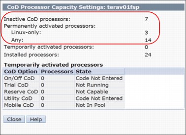
Figure 1-11 CoD Processor Capacity Settings showing activated IFL processors
The lshwres command is updated to show the number of processor units that are configurable for either Linux only or all operating system workloads (Example 1-9).
Example 1-9 Syntax of the lshwres command and its output
lshwres -m <managed system> -r proc --level sys configurable_sys_proc_units=10.0,curr_avail_sys_proc_units=1.0,pend_avail_sys_proc_units=0.0,installed_sys_proc_units=16.0,deconfig_sys_proc_units=0,min_proc_units_per_virtual_proc=0.05,max_virtual_procs_per_lpar=256,max_procs_per_lpar=256,max_curr_virtual_procs_per_aixlinux_lpar=64,max_curr_virtual_procs_per_vios_lpar=64,max_curr_virtual_procs_per_os400_lpar=64,max_curr_procs_per_aixlinux_lpar=64,max_curr_procs_per_vios_lpar=64,max_curr_procs_per_os400_lpar=64,max_shared_proc_pools=64,configurable_sys_proc_units_all_os=7.0,configurable_sys_proc_units_linux=3.0
The configurable_sys_proc_units_linux=3.0 parameter indicates that 3.0 processor cores are configured for Linux only workloads.
|
Notes:
•An additional -F flag is required if the expected values are not shown in the output.
•If configurable_sys_proc_units_linux is 0, it is not shown in the default output. It is shown only when -F is specified.
•If configurable_sys_proc_units_all_os = configurable_sys_proc_units, configurable_sys_proc_units_all_os is not shown in the default output, it is shown only when -F is specified.
•If the managed system does not support Power IFL compliance monitoring, these attributes are invalid.
|
The updated managed system properties tab now shows the number of Linux only and any operating system processors that are licensed in the system (Figure 1-12).

Figure 1-12 GUI window output to show the Linux only and all OS processors
Compliance monitoring assistance
For certain models of IBM Power Systems servers, the HMC shows a message if the managed system is not in compliance with the Power IFL license terms.
Compliance monitoring assistance is available on the following models with firmware version 7.8.1 or later:
•9119-FHB
•9117-MMD
•9179-MHD
System firmware on supported models periodically computes the actual processor core consumption.
|
Note: If a determination is made that your system is out of compliance with the processor core license terms, the HMC displays a message every hour. You must be logged in to the HMC GUI to see these messages; otherwise, they are discarded.
|
On HMC V8.8.1.0 or later, you can see the license configuration for a managed server with Power IFL activations in the HMC server properties Processors tab.
Two categories are listed in the Configurable section:
•Processors that are listed as Linux only represent the number of Power IFL processor cores.
•Processors that are listed as Any can be used for any (general purpose) workload.
This same information is available in the CoD Processor Capacity Settings window.
Compliance conditions
The system records an entry in the CoD history log when an out of compliance condition is first detected.
When the number of out of compliance processor units changes, an A7004735 system reference code (SRC) is logged.
If a system is out of compliance for 24 continuous hours, an A7004736 SRC is logged as a serviceable event.
If you determine that your system is out of compliance, you must correct the problem. Reduce the processor usage of one or more of the running AIX, IBM i, or VIOS partitions on the managed system, reduce processor usage through dynamic partitioning, or shut down or suspend a partition.
1.2.15 Save Area improvements
Starting with HMC V8.8.1.0, many improvements were made in the ability to recover the data in the configuration Save Area. With this improvement, recovery of the Save Area data is possible when corruption occurs on the HMC and service processor and there are no good backups from which to restore.
In previous HMC versions, the recovery consisted of multiple commands, which were available only to Product Engineers, to recover the Save Area configuration. These commands are now combined into the mkprofdata command.
The mkprofdata command also can convert the Save Area data in to an XML file to enable verification of the data before using it for a recovery or restore operation. Previously, this task could be done only by restoring the Save Area data.
The authorization to run the mkprofdata command is added to the hmcpe and hmcsuperadmin task roles.
|
Note: Use the mkprofdata command only when there are no other options and normal operations of recovery is not working.
|
Re-creating Save Area data configuration from the POWER Hypervisor
If the Save Area data must be re-created, run mkprofdata to re-create the Save Area configuration with the following syntax:
mkprofdata -r sys - m <System Name> - o recreate -s sys -v
|
Note: This command can be run only when the managed system is in a standby or operating state.
|
If the Save Area data must be recovered, run mkprofdata. The output of a successful recovery is shown in Example 1-10.
Example 1-10 Successful mkprofdata output
hscroot@hmc8:~> mkprofdata -r sys -m SystemB -o recreate -s sys -v
Service processor and management console data backups taken and saved with the names FSP_1399485387564 , MC_1399485387564
Verification of save area directory objects is complete
Initialization of save area is complete
Execution of recover operation is complete
Update of partition attributes, profiles, and associations is complete
Example 1-11 shows where mkprofdata recovers only partial data. The output shows that mkprofdata successfully recovered only logical partition IDs 1, 2, and 3.
Example 1-11 Partial successful mkprofdata output
hscroot@hmc8:~> mkprofdata -r sys -m SystemB -o recreate -s sys -v
Service processor and management console data backups taken and saved with the names FSP_1399485387564 , MC_1399485387564
Verification of save area directory objects is complete
Initialization of save area is complete
Execution of recover operation is complete
PartitionId of partially updated Partitions attributes, profiles and associations are { 1,2,3 }
Converting Save Area configuration data from a binary file to XML
The Save Area data is in binary format, and it is difficult to check whether there are consistency issues with the data.The mkprofdata command can convert the Save Area data to XML format so that the data that is contained in the Save Area is checked before it is used for a recovery or restore operation. It also checks the consistency of the data because the command generates an error if the data is inconsistent.
To convert the Save Area data to an XML format, run mkprofdata with the following syntax:
mkprofdata -r sys -o createxml -m <system name> -x <xmlfile name>
Example 1-12 shows the conversion of Save Area data to XML format that is saved to the user home directory.
Example 1-12 Convert Save Area data to XML format by using mkprofdata
hscroot@hmc8:~>mkprofdata -r sys -o createxml -m SystemA -x 08052014data
hscroot@hmc8:~>ls
08052014data.xml 08052014data_dir.xml tmp
hscroot@hmc8:~>
|
Note: The mkprofdata command also can be run in Power Off condition, regardless of the server connection.
|
1.2.16 Dynamic Platform Optimizer
The Dynamic Platform Optimizer (DPO) is a PowerVM virtualization feature that is designed to improve partition memory and processor placement (affinity) on Power Servers. The server must be running firmware level 760 or later. DPO determines an optimal resource placement strategy for the server based on partition configuration and hardware topology on the system. It performs memory and processor relocations to transform the existing server layout to the optimal layout. This process occurs dynamically while the partitions are running.
Starting with HMC V8.8.1.0, the HMC v8 added the ability to schedule DPO from the HMC GUI. In earlier HMC versions, DPO was available only on the CLI and had to be run manually.
|
Note: For a complete explanation about DPO and how to perform DPO from the CLI, see Chapter 15, “Dynamic Platform Optimizer”, of IBM PowerVM Virtualization Managing and Monitoring, SG24-7590.
|
Scheduling DPO from the HMC Enhanced+ Interface
To schedule a DPO task to either start monitoring or to perform DPO from the HMC GUI, complete the following steps:
1. In the navigation pane, click the Resources icon, select All Systems, select the server and click Actions → Schedule Operations, as shown in Figure 1-13.

Figure 1-13 Schedule operations from the HMC Actions menu
2. Create a schedule in the Customize Scheduled Operations window by clicking Options → New, as shown in Figure 1-14.

Figure 1-14 Customize Schedule Operations window
3. If the system can perform DPO, a new task, named Monitor/Perform Dynamic Platform Optimize, is shown (Figure 1-15). Select that task and then click OK.

Figure 1-15 Add a Scheduled Operation window
From the Set up a Scheduled Operation window, you can set up the task (Figure 1-16).

Figure 1-16 Set up a Scheduled Operation task: Date and Time tab
On the Repeat tab (Figure 1-17), you can set repeating operations.

Figure 1-17 Set up a Scheduled Operation task: Repeat tab
On the Operations tab (Figure 1-18), you can configure DPO thresholds, alerts, and actions.

Figure 1-18 Set up a Scheduled Operation task: Options tab
The Options tab has these sections:
•Target of Operation
Shows the System name, Potential Affinity Score, and Current Affinity Score.
•Affinity Threshold
Sets the Server Affinity Threshold and Server Affinity Delta Threshold (Potential-Current).
•Alert/Actions
Configures a system alert email when the server reaches a certain condition.
•Perform Dynamic Platform Optimization
Select Automatically Perform a Dynamic Platform Optimization (DPO) to perform DPO automatically when Server Affinity Threshold is less than Current Affinity Score, and the server Affinity Delta (Potential Affinity Score minus Current Affinity Score) is greater than the Server Affinity Delta Threshold.
1.2.17 Power Enterprise Pools and the HMC
Each Power Enterprise Pool is managed by a single master HMC. The HMC that is used to create a Power Enterprise Pool is set as the master HMC of that pool. After a Power Enterprise Pool is created, a redundant HMC can be configured as a backup. All Power Enterprise Pool resource assignments must be performed by the master HMC. When powering on or restarting a server, ensure that the server is connected to the master HMC, which ensures that the required Mobile Capacity on Demand resources are assigned to the server.
The maximum number of systems in a Power Enterprise Pool is 32 high-end or 48 mid-range systems. An HMC can manage multiple Power enterprise pools, but is limited to 1000 total partitions. The HMC can also manage systems that are not part of the Power Enterprise Pool. Powering down an HMC does not limit the assigned resources of participating systems in a pool, but does limit the ability to perform pool change operations.
After a Power Enterprise Pool is created, the HMC can be used to do the following functions:
•Mobile Capacity on Demand processor and memory resources can be assigned to systems with inactive resources. Mobile Capacity on Demand resources remain on the system to which they are assigned until they are removed from the system.
•New systems can be added to the pool and existing systems can be removed from the pool.
•New resources can be added to the pool or existing resources can be removed from the pool.
•Pool information can be viewed, including pool resource assignments, compliance, and history logs.
Power Enterprise Pools qualifying machines
To qualify for use of the Power Enterprise Pool offering, a participating system must be one of the following systems:
•IBM Power E880 with POWER8 processors, designated as 9119-MHE
•IBM Power E870 with POWER8 processors, designated as 9119-MME
•IBM Power 795 with POWER7 processors, designated as 9119-FHB
•IBM Power 780 with POWER7+ processors, designated as 9179-MHD
•IBM Power 770 with POWER7+ processors, designated as 9117-MMD
Each system must have installed Machine Code release level 7.8.0, or later, and be configured with at least the minimum amount of permanently active processor cores (listed next). Processor and memory activations that are enabled for movement within the pool will be in addition to these base minimum configurations.
Power Enterprise Pool configuration requirements
The two types of pools are as follows:
•The Power 770 and E870 pools
•The Power 780, 795, and E880 pools
Static requirements are as follows:
•The Power 770 and 780 systems require a minimum of 4 static processor activations.
•The Power 870 and 880 require a minimum of 8 static processor activations.
•The Power 795 requires a minimum of 24 static processor activations.
•For all systems, 50% of memory must be active, and a minimum of 25% of the active memory must be static memory.
All the systems in a pool must be managed by the same HMC or by the same pair of redundant HMCs. If redundant HMCs are used, the HMCs must be connected to a network so that they can communicate with each other. The HMCs must have at least 2 GB of memory.
An HMC can manage multiple Power Enterprise Pool and can also manage systems that are not part of a Power Enterprise Pool. The maximum number of systems an HMC can manage is 32 high-end systems, 48 mid-range, or 48 low-end systems. An HMC can manage a maximum of 1000 total partitions. Systems can belong to only one Power enterprise pool at a time.
|
Note: Power Enterprise Pools are not available on the IBM Flex System® Manager.
|
For more details about Power Enterprise Pools, see the following web page:
For configuration of Power Enterprise Pools, see 5.11.5, “Managing Power Enterprise Pools” on page 418.
1.2.18 The myHMC application
With the myHMC Android or iOS application, you can connect to and monitor managed objects of your HMC. For more information, see Appendix A, “myHMC” on page 553.
1.3 Hardware Models
This section describes the hardware models available for the HMC Version 8.
The HMC Version 8 supports the following HMC machine types:
•7042-C08
•7042-CR5
•7042-CR6
•7042-CR7
•7042-CR8
•7042-CR9
The following illustrations identify each of the machine type 7042 models and show the cable connections located on the back of each HMC model.
Figure 1-19 shows the front view of HMC mode 7042-C08.

Figure 1-19 Model 7042-C08 (front view)
Figure 1-20 shows the front view of Model 7042-CR5.
.gif)
Figure 1-20 Model 7042-CR5 (front view)
Figure 1-21 shows the front view of Model 7042-CR6.
.gif)
Figure 1-21 Model 7042-CR6 (front view)
Figure 1-22 shows the front view of Model 7042-CR7 or 7042-CR8 (front view of the server model with a 2.5-inch hard disk drive).
.gif)
Figure 1-22 Model 7042-CR7 or 7042-CR8 (front view with a 2.5-inch hard disk drive)
Figure 1-23 shows Model 7042-CR7 or 7042-CR8 (front view of the server model with a 3.5-inch hard disk drive).
.gif)
Figure 1-23 Model 7042-CR7 or 7042-CR8 (front view with a 3.5-inch hard disk drive)
Figure 1-24 shows the rear view of Model 7042-CR7 or 7042-CR8.
.gif)
Figure 1-24 Model 7042-CR7 or 7042-CR8 (rear View)
Figure 1-25 shows Model 7042-CR9 (front view of the server model with 2.5-inch hard disk drives).
.gif)
Figure 1-25 Model 7042-CR9 (front view of the server model with 2.5-inch hard disk drives)
Figure 1-26 shows the rear view of Model 7042-CR9.
.gif)
Figure 1-26 Model 7042-CR9 (rear view)
For more details about the Model 7042-CR9, see the following web page:
..................Content has been hidden....................
You can't read the all page of ebook, please click here login for view all page.